Introduction
In today's photovoltaic (PV) industry, silicon solar cells dominate almost 90% of the world's PV production due to their low cost, good efficiency, exceptional reliability, together with the high natural abundance of the silicon material. Even though alternative materials have proven promising for solar cells application, such as III–V semiconductors, quantum dots/wires, and organics,[Reference Bush, Kevin, Palmstrom, Zhengshan, Boccard, Cheacharoen, Mailoa, McMeekin, Hoye, Bailie, Leijtens, Peters, Minichetti, Rolston, Prasanna, Sofia, Harwood, Ma, Moghadam, Snaith, Buonassisi, Holman, Bent and McGehee1–Reference McMeekin, Sadoughi, Rehman, Eperon, Saliba, Hörantner, Haghighirad, Sakai, Korte, Rech, Johnston, Herz and Snaith3] however, a significant amount of research is continuously being conducted on unconventional techniques to exploit monocrystalline silicon solar cells in an attempt to maximize their light harvesting and increase their power output for the same ground area. These methodologies range from innovative light trapping schemes[Reference Branham, Hsu, Yerci, Loomis, Boriskina, Hoard, Han and Chen4–Reference Campbell and Green6] to advanced cell designs,[Reference Taguchi, Kawamoto, Tsuge, Baba, Sakata, Morizane, Uchihashi, Nakamura, Kiyama and Oota7–Reference Bullock, Hettick, Geissbühler, Ong, Allen, Sutter-Fella, Chen, Ota, Schaler, Wolf, Ballif, Cuevas and Javey10] creative doping profiles,[Reference Cuevas, Sinton, Midkiff and Swanson11–Reference Biancardo, Taira, Kogo, Kikuchi, Kumagai, Kuratani, Inagawa, Imoto and Nakata14] and cutting-edge manufacturing techniques.[Reference Liu, Masuda, Nagai, Miyazaki, Takano, Takano, Yoshigahara, Sakai, Asai and Kondo15–Reference Edler, Mihailetchi, Koduvelikulathu, Comparotto, Kopecek and Harney18] As a matter of fact, the ultimate goals in PV research are (i) to increase the efficiency of solar cells, (ii) enable them to capture the maximum amount of sunlight, (iii) reduce heat generation, and (iv) mitigate dust accumulation problems.
The harvesting of sunlight can be maximized by equipping solar modules with a mechanical sun-tracking system so that the light rays always fall perpendicularly on the surface of the cell as the orientation of the sun changes during the day and over the year. However, such systems add to the total cost and weight of the solar module and make it unsuitable for many applications, including the rooftop of houses and offices. In addition, solar cells should be designed not only to capture light from the direct exposure to light (direct beam), but they should also be able to exploit energy given out in form of diffuse beam and recycle the reflected beams from the background and surroundings. To achieve these purposes, multiple pioneering techniques have been developed including the bifacial structure of silicon solar cells, which are capable of harvesting the sunlight reflected by the background, and therefore promise an increase in power output with respect to traditional solar cells by up to ~35%.[Reference Aoyama, Aoki, Sumita, Yoshino and Ogura19–Reference Minemoto, Okamoto, Omae, Murozono, Takakura and Hamakawa21] Another creative method is based on the fabrication of micro-spherical silicon solar cells to collect direct and diffuse beams with better efficiency;[Reference Kenichi22,Reference Zhang, Du, Shum, Cai, Le, Chen, Duck, Fell, Zhu and Gu23] however, the microspheres are integrated on a flat substrate and, therefore, cannot make use of the background reflected beams. Other techniques focused on solving the heat generation/dissipation and dust accumulation challenges using unique solar cell stacks and encapsulation materials.[Reference Wang, Xie, Ni, Wan, Ou, Zheng and Sun24–Reference Chiadini, Fiumara, Scaglione and Pulsifer26] Nevertheless, all of the aforementioned works focused on and tackled only one aspect of PV research challenges.
Here, we demonstrate an innovative spherical solar cell design that is capable of harvesting light three-dimensionally by tracking direct sunlight, exploiting diffuse beam, and recycling background reflected light. Our design is inspired by the large spherical eyes of houseflies, which increase their angular field of view and enable them to see 270° around them in the horizontal plane,[Reference Chiadini, Fiumara, Scaglione and Pulsifer26] in addition to sunflowers that track the sunlight during the day, all year. Moreover, the spherical solar cell architecture is based on monocrystalline silicon solar cells with high efficiency (19%) and is fabricated using a corrugation technique that transforms rigid solar cells into flexible ones with a maintained electrical performance.[Reference Bahabry, Kutbee, Khan, Sepulveda, Wicaksono, Nour, Wehbe, Almislem, Ghoneim, Torres Sevilla, Syed, Shaikh and Hussain27–Reference El-Atab, Shamsuddin, Bahabry and Hussain31] Finally, the corrugation technique and spherical design of the solar cells enhance heat dissipation and reduce dust accumulation.
Results and discussion
Spherical solar cells design and performance
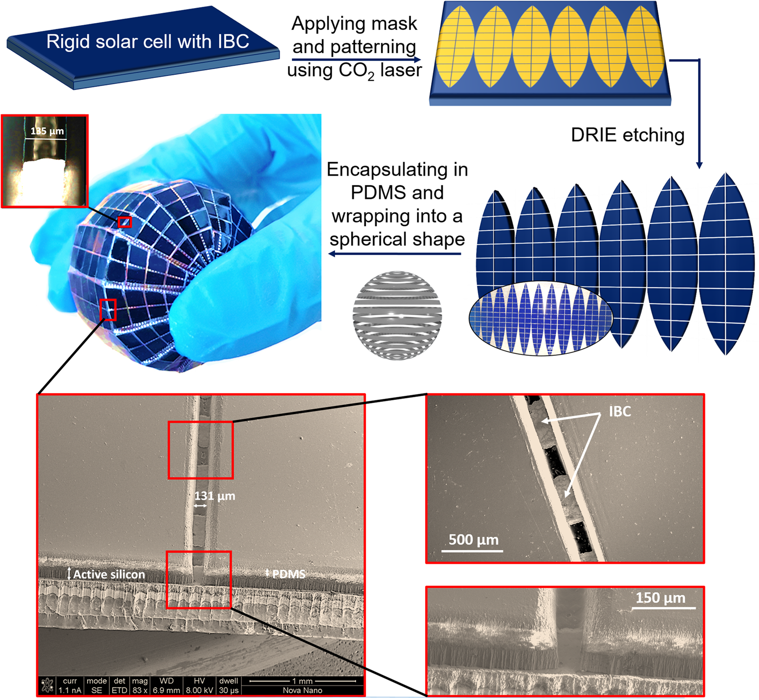
The spherical solar cell is fabricated using our previously developed corrugation technique applied on commercial grade single-crystal silicon solar cells (25 in2) with interdigitated back contacts (IBC) and 19% efficiency. It is worth to note that 19% refers to the efficiency of the commercial grade solar cell as demonstrated and reported in our previous work.[Reference Bahabry, Kutbee, Khan, Sepulveda, Wicaksono, Nour, Wehbe, Almislem, Ghoneim, Torres Sevilla, Syed, Shaikh and Hussain27–Reference El-Atab, Shamsuddin, Bahabry and Hussain31] The corrugation method creates 138-μm-wide grooves within the solar cell, resulting in a flexible structure with a 5.6% loss of total area (Fig. 1). As a result, islands are obtained that are readily interconnected by the IBC grid. Polydimethylsiloxane (PDMS) material is used as the hard mask during the fabrication process and shows no degradation in transmission characteristic. Moreover, PDMS is spin-coated on the corrugated solar cell before folding it into a spherical shape to encapsulate the solar cell.

Figure 1. Fabrication process flow of the spherical solar cell. The spherical solar cell is fabricated using a corrugation technique based on creating alternate grooves in commercially available monocrystalline solar cells. IBC structure in the spherical solar cell is depicted. Inset shows the ~135-μm-wide grooves in the corrugated solar cell.
In fact, it was previously shown that the corrugation technique allows the transformation of the rigid solar cell into a flexible and spherical one with no degradation in the original electrical performance.[Reference Bahabry, Kutbee, Khan, Sepulveda, Wicaksono, Nour, Wehbe, Almislem, Ghoneim, Torres Sevilla, Syed, Shaikh and Hussain27–Reference El-Atab, Shamsuddin, Bahabry and Hussain31] It is also important to note that the projection area of the spherical cell takes into consideration the etched areas of silicon due to the corrugation (the projection area is 10.7 cm2, while the ground area is 11.34 cm2). The average figures of merit [fill factor (FF) = 75.82 ± 0.9%, efficiency (η) = 18.93 ± 0.4%, V oc = 0.644 ± 0.05 V, and J sc = 38.96 ± 1.1 mA/cm2] of spherical solar cells are reported where 10 devices are characterized with a small standard deviation (error bar).
Background reflection effect
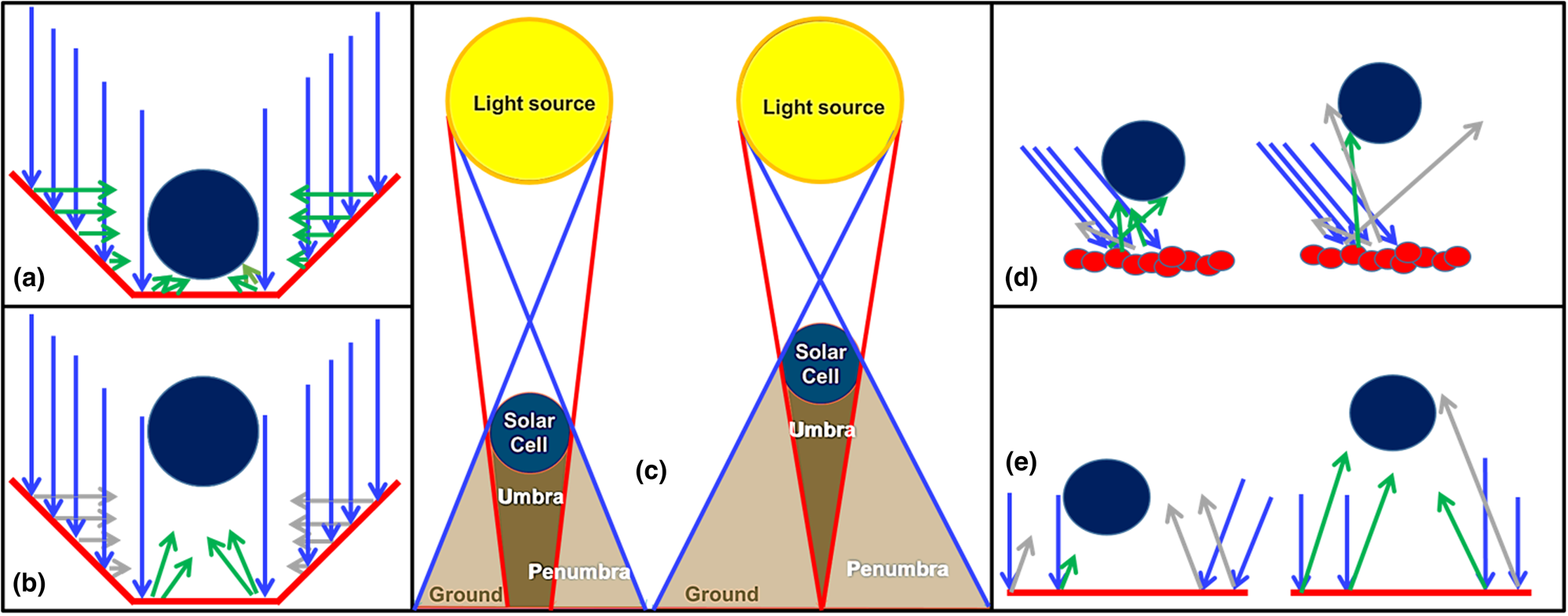
The spherical solar cell is capable of exploiting and recycling background reflected light. To confirm this, the power output of the spherical solar cell is measured using the solar simulator under 1 Sun AM 1.5 G with different background reflective materials including black paper, white paper, sand, aluminum paper, and aluminum cup (Supplementary Fig. S1). In addition, the effect of the height of the spherical solar cell on its capability to capture reflected light is studied. It is worth to first explain that the white paper and sand show a diffuse reflectance of ~85% and ~25%, respectively. The aluminum paper, on the other hand, shows a specular reflectance of ~88%. Finally, the black paper shows a negligible diffuse reflectance (~3%) [Fig. 2(a)]. The power output from both spherical and flat cells having the same projection area is obtained using a solar simulator in air (AM 1.5 Global Spectrum with 1000 W/m2 intensity and spectral mismatch correction at room temperature). The results show that the spherical solar cell is capable of capturing the largest amount of back-reflected light when the aluminum cup is used with a 1 cm height, resulting in a 101% increase in power output compared to the flat solar cell with the same ground area [Figs. 2(b)–2(d); Supplementary Figs. S2 and S3 and Videos S1 and S2]. The maximum increase in power output using a spherical cell at an optimum height (based on the background reflective material) is compared with that of a flat cell at an optimum height of 0 cm shown in Fig. 2(d). In fact, the hexagonal aluminum cup allows for reflexive reflection where the incident light on the sides on the cup with 45° angle, follow Snell's law, and reflect back with a reflection angle of 45°, allowing the spherical solar cell to capture them [Fig. 3(a)]. As the height of the cell is increased, the reflected light by the bottom parts of the sides of the cup are not captured by the spherical solar cell, and as a result, the output is reduced [Fig. 3(b)]. Moreover, the spherical solar cell shows an angular invariant performance due to its symmetrical structure [Fig. 2(c)].

Figure 2. Background reflection effect on the output of the spherical solar cells. (a) Reflectance measurements of the different used background materials. The specular reflectance of aluminum is reported, while diffuse reflectance of the other materials is measured. (b) Measured power output by the spherical solar cell using different reflective backgrounds (white paper, black paper, aluminum paper, sand, and aluminum cup) and at different heights ranging from 0 to 10 cm. (c) Power output from a spherical solar cell at different tilt angles. Inset showing the measurement setup for the power output characterization with different reflective backgrounds and at different heights. The measurements are conducted using a solar simulator (Newport, Oriel Class A, Sol3A, Irvine, CA, USA) with a source meter (Keithley 2420-C) under 1 Sun illumination at AM 1.5 G with intensity 1000 W/m2 intensity with a white background and at a height of 1 cm. (d) Increase in power output of spherical solar cells with different reflective backgrounds with respect to the spherical and flat solar cells with no reflective background and with the same ground area of 11.34 cm2.

Figure 3. Light reflection mechanism based on the background material. (a) Hexagonal aluminum cup concentrating the reflected light by the sides onto the spherical solar cell. When the spherical cell is at the bottom of the cup, the cell absorbs the light reflected by the tilted sides of the cup. (b) The spherical solar cell with a hexagonal aluminum cup reflective background misses the reflected light by the sides of the cup as it is brought up higher. (c) The umbra and penumbra regions of the solar cell shadow are shown when the spherical cell is placed at different heights. (d) With diffuse reflection, spherical solar cells have a higher probability of harvesting reflected light at lower heights. (e) The height of the spherical cell must be higher to capture the parallel-reflected light from a mirror-like surface. Blue arrows represent incident light, green arrows represent light rays that are harvested by the spherical solar cell, while gray arrows represent the ones that are not captured by the cell.
Using the white paper as the reflective background material, a maximum increase in power output of 39.7% can be achieved at a height of 2 cm. Similarly, with sand, the largest increase in power output is achieved at a height of 2 cm where the output is enhanced by 14.8% with respect to the flat cell. As a matter of fact, the lower limit of the spherical solar cell height is determined by the shadowing effect from the solar cell. The shadow is generally composed of umbra, which represents the darkest region of the shadow with no light, and penumbra, which is the lighter region of the shadow with partial light.[Reference Rajkumar, Haque and Hrudey32] As the solar cell is brought closer to the background, the umbra region is increased, resulting in loss of the potential area for light back reflection [Fig. 3(c)].
On the other hand, the highest increase in power output using the aluminum paper with respect to the flat solar cell is obtained at a height of 7 cm. The achieved increase in power output, in this case, is only 20.25%, which is considerably smaller than the improvement achieved using the white paper (39.7%), even though both materials show similar reflectance values. The reason is due to the different type of reflectance obtained in each case. With the white paper, diffuse reflection allows the incident light to reflect in all directions, following Lambert's law, thus increasing the probability of harvesting more light by the spherical solar cell [Fig. 3(d)]. However, the aluminum paper, having a mirror-like surface, reflects light in one direction; thus, the probability of capturing the reflected light is significantly lower resulting in a lower power output [Fig. 3(e)]. In addition, with specular reflection, the higher the solar cell, the higher the probability of harvesting the parallel-reflected rays, which explains the 7 cm needed to maximize the power output. The upper limit for the height of the spherical solar cell is, therefore, determined by the type of reflectance in addition to the size of the solar cell.
Thermal performance
Monocrystalline silicon solar cells generally have a temperature coefficient of 0.5%/°C. The spherical structure of the solar cell enables the reduction of heat generation within the cell and, therefore, reduces its effect on efficiency degradation. To prove this, the spherical and flat cells with a similar projection area are continuously shone with light under 1 Sun using the solar simulator, and the temperature and power output from both cells are measured every ~1.5 min [Fig. 4(a)]. It is important to mention that the temperature on the highest point on the spherical solar cell is recorded, using an infrared sensor, which is expected to show the highest temperature on the spherical structure due to its direct exposure to perpendicular light rays. The results show that the spherical cell provides ~10% lower maximum temperature, while the power output shows 9.6% improvement over the flat one. In fact, at a temperature of 47 °C (starting from 21 °C), the flat solar cell shows a degradation in power output by 14.13% which is consistent with the monocrystalline silicon temperature coefficient. While in the case of the spherical cell, the temperature reaches 41.2 °C (starting from 21 °C), with a 5.87% degradation in power output. Using the same temperature coefficient, this converts to an average temperature of 32.1° C for the spherical cell, which is 31.6% lower than the temperature of the flat cell (47 °C).

Figure 4. Thermal and dust performance of the spherical solar cells. (a) Measured reduction in power output with respect to the original value obtained at 21 °C after exposing the solar cells to 1 Sun using the solar simulator for different durations. Inset shows the infrared thermometer reading the temperature on the spherical solar cell. (b) Temperature distribution of the spherical solar cell measured using an infrared camera when exposed to light. (c) Number of dust particles deposited on the surface of both solar cells after exposing them to the dust generator. The graph shows that as the tilt angle of the flat cell is reduced, the number of dust particles that are deposited on the surface of the cell increases. (d) Spherical solar cell illustration showing that the yellow area with a tilt angle below 40° accumulates dust the most.
To better understand the results, the spherical solar cell is shone with light and the temperature distribution is recorded using an infrared camera [Fig. 4(b)]. The result shows a large range of temperature distribution over the surface of the cell, where the area exposed with direct light, perpendicularly to its surface, heats up the most, while other regions that receive light rays with a nonzero angle of incidence show a reduced temperature. A ~12 °C gap between the top (directly exposed to light) and bottom (shadowed) areas of the spherical solar cell is recorded. This means that the top area shows a larger reduction in efficiency than bottom areas. However, in the case of a flat solar cell receiving light rays at the same tilt angle, the temperature will be uniform across its surface area (Supplementary Video S3). As a result, the integrated power output over the complete surface area of the spherical cell will be higher than that generated by the flat cell.
Another key result to notice is the lower maximum temperature recorded with the spherical cell than with the flat cell (41.2 versus 47 °C, respectively), although both regions were receiving light perpendicularly, at 0° incidence angle. To explain the observed result, finite element (FEM) analysis is conducted using the COMSOL™ (Supplementary Fig. S4). Boundary conditions for both geometries are shown in Supplementary Fig. S5. The simulation is performed in order to analyze the heat dissipation in spherical and flat solar cells with a similar total surface area when exposed to 1 Sun for 6 h with a forced natural convection (Supplementary Video S4). The results show that the spherical shape of the solar cell allows a decrease in the average temperature by 10% due to heat dissipated by natural convection [Supplementary Figs. S6(a) and S6(b)]. For spherical and flat solar cells with the same ground area, the total surface area of the spherical solar cell is significantly larger than the flat one, for instance, in our case, the total surface area of the flat cell is 11.34 cm2, while the surface area of the spherical cell is 42.8 cm2. Thus, additional improvement in heat dissipation by natural convection is expected. This analysis validates the measured results and confirms the advantages of the spherical structure in terms of mitigating the heat challenges in solar cells.
Dust challenges
The accumulation of dust on solar cells act as a screening effect and cause a degradation in the cell efficiency and power output. To confirm the merits of the spherical solar cell over the flat one in terms of dust challenges, a customized dust generator is set up where 2.04 g of ~140 μm particles is blown over both samples with different tilt angles and same ground area. The weight measurements after the dust generation process show that the flat solar cell accumulates more dust at smaller tilt angles, while the spherical cell shows a consistent particles accumulation at different tilt angles [Fig. 4(c)]. It is also observed that the dust accumulation on the flat structure is most pronounced at tilt angles below 40°. Therefore, to compare the effect of the dust accumulation on both structures with the same ground area, it is crucial to calculate the area A on the spherical cell which shows tilt angles below 40° [Fig. 4(d)]:
This shows that, for the same ground area, the spherical structure accumulates dust in a significant manner on an area A of 0.47 πR 2, which is almost half the area available for dust accumulation in the case of the flat cell.
Conclusions
In conclusion, we have demonstrated a high efficiency nature-inspired spherical solar cell based on monocrystalline silicon. The fabrication of the spherical cell is achieved using a corrugation technique that converts rigid photovoltaic devices into flexible ones with no observable degradation in the initial electrical performance. The spherical solar cells are shown to be able to collect and harvest sunlight three-dimensionally. More specifically, the spherical solar cell acts as a sun-tracking flat cell with the same ground area, and horizontal and vertical flat cells with twice the ground area in terms of the diffuse and reflected beam, respectively. Using different background reflective materials such as the hexagonal aluminum cup and the white paper, the spherical solar cell can achieve an increase in power output by 101% and 39.5%, respectively, with respect to a flat solar cell with the same ground area. In addition, we have shown that the spherical structure shows advantages in terms of heat generation/dissipation where the average temperature is 31.6% lower than the flat cell with the same ground area. Finally, we have proven that the dust accumulation of flat solar cells is more evident than in the case of the spherical cell with the same ground area. We believe that the presented results create new engineering opportunities for the well-established silicon solar cells industry in order to achieve a higher solar power output for the same ground area without having to move to the higher cost and higher efficiency materials and processes.
Supplementary material
The supplementary material for this article can be found at https://doi.org/10.1557/mrc.2020.44.
Acknowledgment
This publication is based upon work supported by the King Abdullah University of Science and Technology (KAUST).


