Introduction
In principle, the uniaxial compressive strength of a solid material is easy to measure. Uniform uniaxial stress is induced in a cylinder or prism of the material and is increased steadily at either a constant strain-rate or a constant stress-rate; the peak stress developed at failure is taken as the uniaxial compressive strength under the prevailing test conditions. In reality, however, uniaxial compressive strength is not easy to measure, since it is very difficult to induce a state of true uniaxial stress. These matters are treated at length by Reference Hawkes and MellorHawkes and Mellor (1970).
In the conventional test, axial force is applied to the ends of a right circular cylinder through steel platens which make direct contact with the test specimen. Friction between the platens and the specimen produces radial restraint so that there is a triaxial state of stress near the end planes of the specimen; the triaxial field is significant over an axial distance of about one specimen radius from the end planes. The introduction of a highly compliant sheet (elastic or plastic) between platen and specimen often changes the sign of radial end forces, but does not eliminate the triaxial stress field. On a different scale, irregularities in the specimen end planes also create localized stress perturbations, and in brittle material these commonly initiate the microcracks that lead to premature failure of the specimen. Further stress gradients can be produced by eccentric loading and by lack of parallelism between specimen end planes or between end planes and loading platens.
In tests that lead to brittle fracture these are serious problems, and they are not easily solved. Since most attempts at solution have proved unsuccessful or impracticable, the usual procedure is to accept positive frictional restraint at the specimen end planes and to use a specimen that is long enough to provide a mid-section that is reasonably free from stress perturbations due to the ends. Extreme care is exercised in specimen preparation to produce end planes that are normal to the axis of symmetry and flat within strict tolerances. A very thin sheet of compressible material (e.g. paper) may be placed between specimen and platens to compensate for very small surface irregularities, and a “locking" spherical seat of suitable design may be used to compensate for small departures from parallelism. Flexure and cracking of the specimen are avoided by strict alignment procedures and by provision of high rigidity in the loading device to avoid rotation or lateral translation of the platens.
This type of procedure has proved acceptable for high-quality laboratory tests on materials such as rocks, ceramics, and concrete. However, these materials are quite stable in typical test environments, in contrast with ice, which is usually tested at very high homologous temperatures.
When ice is tested at temperatures above -15°C or so, it seems to be extremely difficult to obtain valid results with the conventional uniaxial compression test, even when great care is exercised. Reference Hawkes and MellorHawkes and Mellor (1972) took exaggerated care in the preparation and testing of right circular cylinders, but at high loading rates they were unable to achieve strength values that approached those measured on specially designed dumb-bell specimens. As a result of such studies on testing technique, Mellor was forced to discard his own data that had been obtained earlier by methods long accepted at CRREL. It seems quite possible that some of the data recorded in the literature suffers from similar gross errors.
In field work in cold regions, it may be unrealistic to seek a solution through fanatical quality control since test quality is often below the standards that are attainable in a research laboratory. The laboratory alternative of using precisely formed dumb-bell specimens may also be impracticable for field operations, especially when tests have to be made on broken material obtained by inexpert core drilling. An attempt has therefore been made to develop an entirely new technique that is capable of giving accurate results with simple equipment under field conditions.
Compliant platens
The ideal way to load a specimen in uniaxial compression would be to apply hydrostatic pressure to the ends of the specimen by means of a fluid that cannot transmit shear stress. This does not appear to be practicable, but it is possible to use compliant solids. The objective is to apply axial normal force through a deformable material that conforms to the shape of the specimen end plane but at the same time to avoid any significant radial stress.
Theoretically, the required result could be obtained by pressing the specimen between platens that have a lower modulus than the specimen but which undergo a radial strain exactly equal to that of the specimen. When specimen and platen have the same diameter, the condition for the radial strains to be equal is that Young’s modulus divided by Poisson’s ratio should have the same value for both specimen and platen materials. Thus, if the platen is to have a modulus significantly lower than that of the specimen, it will also need to have a Poisson’s ratio that is proportionately low; this does not seem to be a practical proposition.
A more reasonable alternative is to use a low-modulus solid that is laterally confined to prevent gross radial deformation. This approach was pioneered by Reference KartashovKartashov and others (1970), who made a compliant platen for rock testing by inserting a low-modulus plug into an open-ended steel cylinder, and by pre-loading it using a screw-in steel plug. With this arrangement, they found that the apparent strength did not vary with the length-to-diameter ratio (L/D) of the specimen over a range of approximately 0.5 to 3.
A low-modulus plug was cast inside an aluminum cylinder as an adaptation of the technique of Katashov and others for ice tests (Fig. 1). To prevent extrusion of the insert, the inside diameter of the confining cylinder was slightly greater (of the order of 0.1 mm) than the diameter of the test specimen at failure (allowing for radial strain). The insert itself was a cast urethane which is similar in mechanical properties to hard rubber. The surface of the insert was faced-off in a lathe with a sharp tool to ensure that it was flat and normal to the axis of the confining cylinder. The notes that follow describe tests that were conducted to validate the performance of compliant platens.

Fig. 1. The lapping plate, the steel polishing jig, and the platens.
Specimen Preparation
Twenty-one specimens were made for each series of tests using the following procedure. A “Lucite" mold was assembled by placing sleeves into its holes (the holes were 0.178 m long and 0.076 m in diameter) and then attaching a base-plate to the mold. Silicone grease was smeared lightly on the outside of the sleeves to facilitate removal of the specimens after they had been frozen. 21 of the 25 holes in the mold were filled with crushed ice from a commercial ice maker. A water passage was provided between the aluminum baseplate and the mold by the use of a wire-mesh spacer. Distilled, de-aired water was poured into one of the empty holes until the ice-filled holes were completely saturated.
To provide unidirectional freezing, insulation was placed on all sides of the mold except the bottom. The specimens were frozen by placing the mold in a cold room for 20 h at -15°C. The specimens were subsequently removed from the mold and stored in a cold room at -7°C until required for testing.
The ice tested in this study had an average grain size of about 1 mm, an average bubble size of approximately 0.4 mm and a density of 0.907 Mg m-3. A melt-water conductivity of 7 X 10⁻⁴ Ω-1 m-1 was measured at 23°C.
For the series 1 and series 3 tests, the specimens were cut to varying lengths so as to give the desired length-to-diameter ratios. They were then placed in the steel polishing jig, shown in Figure 1 with the lapping plate, and lapped until a mirror finish was obtained.
In the series 2 tests, the specimen length was kept approximately constant with a L/D ratio of ≈ 2.35. About half of the specimens were prepared with lapped ends as described above, the other half were cut accurately with a hand mitre saw. Rubber membranes were then placed on the specimens and they were stored in plastic bags in an ice-saturated atmosphere to minimize sublimation.
Test Apparatus and Procedure
Figure 2 shows the MTS testing machine and the environmental chamber used for the compression tests. The machine has an overall stiffness of the loading system equal to 3.6 X 10⁸kg m-1. The hydraulic closed-loop servo system has a response time of 0.5 ms. The environmental chamber is part of a Bemco refrigeration unit capable of maintaining temperatures to within ±0.2°C down to -57°C. A nominal test temperature of -9°C was used for all tests. A machine speed of 0.042 m S-1 was used for the series 1 tests and a speed of 0.004 2 m S-1 was used for the series 2 and series 3 tests.

Fig. 2. (left) The MTS testing machine and environmental chamber.
The platens were made by casting a urethane mix directly in an aluminum cylinder and allowing the mix to cure at room temperature. This urethane has a specific gravity of 1.10 and a Shore A hardness of 94 (ASTM D412). After curing, the ends of the urethane were faced off on a lathe with a sharp tool. Bubbles with an average diameter of 1 mm were observed on the surface of the urethane. These were caused by air included during the mixing process. Subsequent to the testing conducted in this study a new casting technique was developed. Urethane which is almost bubble-free can be successfully cast using a simple centrifugal method, as described in the Appendix.
The specimens were placed in the urethane compliant platen (Fig. 3) and centered prior to testing. A ball-seat platen, attached to the end of the hydraulic actuator, was positioned to make a no-load contact with the urethane platens. During a test, the load was measured with a MTS model 661.22 load cell, and recorded on a Tektronix oscilloscope model R5103N.

Fig. 3. (right) The compliant platen. Figures in parentheses are millimeters.
Test Results
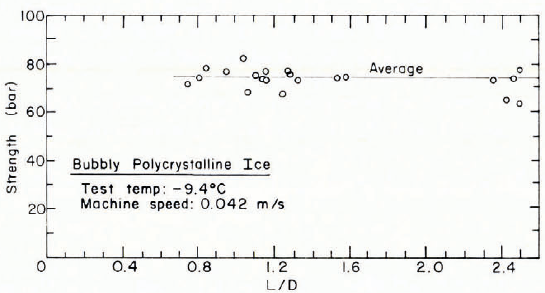
Results for the series 1 tests are shown in Table I and Figure 4. The average strength for the 21 tests was 73.8 bar, with a 13.6% maximum deviation from that mean. There was no definite trend over the range of L/D ratios from 0.74 to 2.5.
TABLE I. RESULTS OF SERIES 1 COMPRESSION TESTS
Bubbly, polycrystalline ice
Test temperature: -9.4°C
Machine speed: 0.042 m s-1
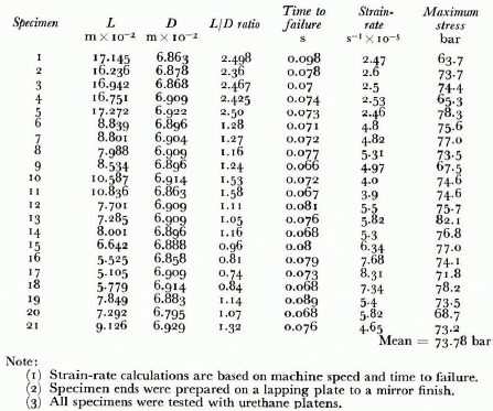

Fig. 4. Strength versus specimen L/D for series 1 tests using urethane platens.
The series 2 test results are shown in Table II and Figure 5. Nineteen of the 21 tests had an L/D ratio between 2.3 and 2.42. The measured strength varied from 13.1 to 81.7 bar depending upon the specimen end preparation and the type of platen used. Table II gives the average values and range for the five specimen end and platen combinations used. There was a 3% difference between the average values of the lapped and saw-cut specimen ends when tested on urethane platens. However, there was a 116% difference between average values when similar specimens were tested on steel platens.
TABLE II. RESULTS OF SERIES 2 COMPRESSION TESTS
Bubbly, polycrystalline ice
Test temperature: -9-4°C
Machine speed; 0.004 2 m S-1


Fig. 5. Strength versus specimen L/D ratio for the series s tests using steel, urethane, and large urethane platens.
Table III gives the results of the series 3 tests. Compressive strengths for the 22 tests in this series are plotted in Figure 6. A thin sheet of paper was interposed between the lapped ends of the specimen and the steel platens to reduce stress concentrations caused by possible surface irregularities in the specimen ends. The results show that the compressive strength doubles as the L\D ratio is decreased from 2.2 to 0.6.
TABLE III. RESULTS OF SERIES 3 COMPRESSION TESTS
Polycrystalline ice
Test temperature: - 9.4°C
Machine speed: 0.004 2 m s-1


Fig. 6. The relationship of strength of ice ta L/D ratio using steel platens.
Discussion
Dependence of uniaxiai compressive strength on specimen L/D ratio has been discussed by Reference Hawkes and MellorHawkes and Mellor (1970), Reference MogiMogi (1966), Reference Newman. and LachanceNewman and Lachance (1964), Reference Obert. and DuvallObert and Duvall (1967), and Reference KartashovKartashov and others (1970). They all conclude that the apparent strength of rocks tested by the conventional method increases for a L/D ratio less than 2.5. The explanation for this effect involves the radial restraint produced by a frictional steel platen on the end of the rock specimen. This restraint delays structural failure and enhances the measured strength. Reference Hawkes and MellorHawkes and Mellor (1970) present results of uniaxial compression tests on various rocks. They point out that apparent compressive strength increases for L/D ratios less than 2.0 and increases very rapidly for L/D ratios less than 1.0. They also point out that one way to achieve radial freedom is to match the radial strain in the platen with the radial strain in the test specimen. Matching these radial strains requires that the ratio of Young’s modulus to Poisson’s ratio (E/v) be the same for both platen and specimen.
Reference Newman. and LachanceNewman and Lachance (1964) conducted tests on concrete prisms. The apparent compressive strength increased with decreasing L/D ratio when steel platens were used and decreased when a thin (1.6 X 10⁻³ m) rubber sheet was interposed between the platen and the specimen. They recommend that the capping material for concrete specimens should have the same ratio of Poisson’s ratio to the compressive modulus (v/E) as the concrete.
Reference KartashovKartashov and others (1970) developed a platen for testing rocks which consisted of a low-modulus insert radially restrained in a high modulus cylindrical yoke. Their tests on rocks showed that the apparent compressive strength increased as L/D decreased for ratios less than 2.5 when high-modulus platens were used. When low-modulus platens were used, the strength decreased as the L/D ratio decreased. However, when the low-modulus insert confined in the cylindrical yoke was used, the strength was essentially constant over an L/D range of 0.5 to 2.75.
The results of the present investigation indicate that cylindrical specimens of ice may be tested down to an L/D ratio of 0.74 with no apparent effect upon the compressive strength when suitably designed compliant platens are employed. Although Young’s modulus for urethane (about 3.8 X 10² bar) is much less than for ice (about 6.9 X 10⁴ bar), a confined urethane platen of suitable diameter provides a compatible radial deformation for ice.
Reference Hawkes and MellorHawkes and Mellor (1970) recommend that specimen ends for rocks should be flat within 2.54-12.7 μm when testing with steel platens. They further recommend that specimens with a diameter greater than 25.4 mm should be flat to within 25.4 μm. Specimens with lapped ends in the present tests had a flatness between 25.4 and 2.54 μm. However, the specimens with saw-cut ends were flat within about 0.5 mm. The 3% difference in strength found between the lapped and saw-cut specimens when tested with the urethane platens (Fig. 5) indicates the ability of these platens to remove stress concentrations due to surface irregularities.
The test results confirm that the diametrical clearance between the specimen and the aluminum cylinder is important. Figure 5 shows that the apparent strength decreased when large platens with a diametrical clearance of 6.5 mm were employed. The optimum design platens had a diametrical clearance of 0.127 mm. This suggests that the large platens experienced radial deformation which induced tensile stresses in the specimen ends and contributed to early failure.
An increase in apparent strength with decreasing L/D ratio when steel platens are used is shown in Figure 6. These results confirm those reported by Reference Hawkes and MellorHawkes and Mellor (1970), Reference Newman. and LachanceNewman and Lachance (1964) and Reference KartashovKartashov and others (1970). Figure 6 shows the average strength at L/D of 2.2 to be about 42 bar for tests with steel platens. Also shown in Figure 6 is the average strength found with the urethane (rubber) platens (see Table I). These results show good agreement with the results of Reference Hawkes and MellorHawkes and Mellor (1972). They found the compressive strength for ice to be considerably lower when right-circular cylindrical specimens were used than when dumb-bell specimens were used. The average strength of ice found with cylindrical specimens and urethane platens in this study is slightly lower than the strength of ice they found with dumb-bell specimens. However, the strain-rate, test temperature and specimen grain size were not exactly the same for the two tests.
The main advantages gained from the use of these platens are: (1) simple procedures are adequate for specimen preparation, and (2) short lengths of core can be utilized. These advantages are of very great significance in field testing where precise technique is not always feasible and the traditional field technique gives highly inaccurate data.
Acknowledgements
The authors gratefully acknowledge the assistance of many personnel of the U.S. Army Gold Regions Research and Engineering Laboratory, especially Jack Karalius, Robert Bonnett, and Frederick Gernhard.
Appendix Centrifugally-Cast Urethane Platens
Casting procedure
In order to obtain a urethane plug which is bubble Tree, it was decided that the plug should be cast in a mold which could be rotated at a high angular velocity. The bottom of the mold was aluminum, other parts were made from “Plexiglas" assembled with a finger-tight press fit. The solid-release agent furnished with the urethane was used on the inside of the mold. The aluminum bottom has a recess in it which fits over a bearing attached to a baseplate. After the urethane arid curing agent had been thoroughly mixed, the viscous solution was poured into the mold and the top of the mold was set in place. The top has two holes for air removal during the rotation operation. The entire mold was then rotated in a drill press. Rotation caused the mix to ride up the sides of the mold due to centrifugal effects. Air, included during the mixing stage, was separated from the urethane at this time.
After rotation of the mold for 1 minute at 4 200 r.p.m., the speed was steadily reduced to zero over a time interval of two minutes. The top of the mold was then removed and the cast was allowed to cure for 12 h before total removal from the mold. The urethane slumped down to the bottom of the mold during the curing interval. The mold was dismantled, the plug remained in the short, cylindrical portion of the mold. The plug was then faced off on a lathe and removed from the short “Plexiglas" cylinder. Young’s modulus for these plugs, measured in uniaxial compression, was found to be about 3.8 X 10² bar. A Poisson’s ratio of 0.45 was obtained for compressive loading.
Assembly of plug and ring
The first platens were made by casting the urethane plug directly in the aluminum ring. However, when these platens were used in tests at -10°C, differential shrinkage caused separation of the plug and the ring. This is explained by the fact that the coefficient of thermal expansion of urethane is about four times that of aluminum.
In order to solve the problem of separation, it was decided that a shrink-fit technique should be used. The urethane plug was cast with a diameter of 0.070 23 m, and the aluminum ring was made with an inside diameter of 0.060, 72 m. For several hours the plug was kept at a temperature of -40°C, while the ring was kept at + 110°C. At these temperatures the plug diameter was less than the diameter of the ring so that assembly was possible. An interference fit of 0.000 3 m was thereby achieved for a -10°C test temperature.
Essentially, bubble-free urethane can be cast successfully using a simple centrifugal method. Close inspection of a plug after it had been cut in half revealed a small region of bubbles in the center of the plug. The diameter of this region was about 1 mm and it constituted about 0.02% of the total plug by volume. Assembly of the urethane plug in an aluminum ring by a shrink-fit technique should prevent separation of the two components when used at low temperatures.
Discussion
L. W. GOLD: DO you consider the flexane platens will still be effective when the ice specimen is subject to ductile deformation?
F. D. HAYNES: I would expect so, but for very slow tests the gap might have to be modified. In our experiments approximate strains in the range 10 -5 to 10-6 were used.
R. FREDERKING: Have you evaluated these platens over a range of strain-rates ? How do you define strain-rate?
HAYNES: Our measurements of strain were approximate. We did not test the platens over a range of strain-rates. The primary purpose of these tests was to determine the feasibility of their use for field testing.
B. MICHEL: How do you measure the real deformation of the ice with such low-modulus plugs?
HAYNES: The actual deformation of the ice was not measured; no strain gauges were used. The approximate strain was calculated by using the machine speed and time to failure.
M. MELLOR: It has been proved conclusively that measurement of platen displacement introduces significant error into the determination of strain for high-modulus materials. The acceptable techniques involve bonded strain gauges, demountable displacement transducers, or non-contact displacement sensors.
R. L. BROWN: HOW does the Young’s modulus of the platen material compare with that of ice for the strain-rates in your experiments?
HAYNES: The modulus of the urethane is about 4 X 10⁷ N m-2. The modulus of ice is about 7 X 10⁹ N m-2.
P. TRYDE: Could you explain the influence of the gap between the specimen and the steel cylinder on the strength?
HAYNES: If the gap is large (e.g. 5 mm), radial tensile stresses will be induced in the specimen ends and result in a lower maximum stress than if the gap is about 0.3 mm. (The specimen diameter is 69.21 mm.)
J. W. GLEN: In removing bubbles from the urethane, why did you centrifuge using an axis of rotation coaxial with the cylinder? If you centrifuge using an axis at right-angles to the axis of the cylinder the material should be pressed into a cylindrical shape at the ends of the mould, rather than climbing the walls of the cylinder and having to drain down into shape again later. This should avoid the small bubbles developing axially in the centre of the resulting plug.
HAYNES: This method is worthy of a trial. If enough urethane mix is used it may eliminate the extremely small bubble region.
D. J. GOODMAN: IS the author familiar with the paper of Reference WuWu and others (1976) who used ice to separate the specimen from the platens? Would he like to comment on this result?
MELLOR: This technique is not really satisfactory. It does not produce “platen matching" unless specimen and cushion diameters are equal, there is a very rough approximation to the dumbbell specimen, but there are still stress perturbations in the specimen.