Introduction and Review of Literature
The development of off-shore exploration for oil and gas in the Arctic and Subarctic regions has motivated the interaction studies of stationary and mobile ice-floes and ice fields with off-shore structures. Various structural forms are used for off-shore towers depending on the location—framed and trussed towers, monopods, and tripods (fixed and gravity-type structures). In this study, the transient interaction of a moving ice field with a stationary monopod structure located at Cook Inlet, Alaska, is considered. Since ice-force records at the site were not available, artificial ice-force records have been generated based on the actual field measurements of Reference BlenkarnBlenkarn (1970). The method used for generating these artificial ice-force records is also described.
Reference Blumberg and StraderBlumberg and Stradcr (1969) presented the first analysis of off-shore structures subjected to ice forces for the monopod structure at Cook Inlet, Alaska, by replacing the effect of the moving ice-floes by a static load at the highest tide level. Reference MatlockMatlock and others (1971) represented the interaction of a moving ice sheet with the structure by a physical model of vertical, elastic-plastic cantilevers, mounted on a smoothly moving rigid base, impacting a spring-mass (single-degree-of-freedom) system. The dynamic response, determined for a “saw-tooth” type of deterministic loading simulated by the model, showed good agreement with earlier field measurements of Reference PeytonPeyton (1968[a]). Sundararajan and Reference Reddy and CheemaReddy ([1974]) used spectral techniques to study the stochastic response of a single-degree-of-freedom (SDOF) model subjected to ice-loading obtained by field measurements (Blenkarn, 1970) at Cook Inlet, Alaska. They noted that the system responded to excitation for ω ≤ ω0 (the fundamental frequency of vibration of the structure), but filtered out the excitations for ω » ω0. This agrees with the independent conclusions arrived by Reference KivisildKivisild (1969), and Reference PeytonPeyton (1966, Reference Peyton1968[a], Reference Peyton[b]) that the force oscillations observed were due to the velocities and vibrations of the ice-floes (whose natural frequencies were usually less than one hertz) rather than due to the structure. Reference KivisildKivisild (1969) estimated that the fundamental frequencies of fluid-supported ice sheets, deforming laterally in dish form, were less than one hertz. Reference RechReeh (1972) derived relationships to determine the natural frequencies and mode shapes of ice sheets vibrating in water and observed that the frequencies of rigid-body motion of floating ice sheets were of the order of one hertz. The power-spectral-density technique for ice-force loading was extended to multi-degree-of-freedom (MDOF) systems by Reddy and Cheema (1974). Reference Reddy and Frankenstein(Reddy and others 1975, Reference Reddy[e1976]) used response-spectrum techniques, widely used in earthquake analysis, to calculate the probable maximum dynamic response of a three-dimensional off-shore structure (idealized as a two-dimensional frame) subjected to impact loads from moving ice sheets. This was the first time response spectra had been developed for ice forces. The added water mass was assumed equal to the mass of water displaced (Reference KingKing, 1974). The ice-force records were digitized using the Nyquist criterion and the stationarity of the chosen ice-force records was verified by the Kolmogorov-Smyrnov test. The work included an extensive literature review on ice-structure interaction. Reference Reddy and FrankensteinReddy and others (1975) extended the power-spectral-density method to three-dimensional, framed, off-shore structures subjected to ice forces and determined the mean-square responses.
Monopod off-shore platforms, either fixed to the bottom or resting on it, have been suggested for exploratory and production drilling purposes in the technical brochures of Selmer (1974, 1975) and Reference Hochtief.Hochtief (1975). The Condeep (Norwegian Contractors, 1975) and Brent Field C (Offshore, 1975) concrete gravity platforms arc similar to monopod structures in their response to ice forces. Imperial Oil Limited examined different types of monopod platforms for off-shore drilling in the Canadian Beaufort Sea; Reference Jazrawi and DaviesJazrawi and Davies (unpublished) presented a detailed procedure for the analysis and design of such structures. Reference Durning and EngleDurning and Engle (1976) described the continuous monitoring techniques used for estimating the response of the Cook Inlet monopod structure to ice forces during three successive winter seasons. Reference UttUtt and others (1976) analysed the recorded dynamic response of the Cook Inlet monopod platform, and simulated the response with computer models. The purpose of the study was to determine the reason for observed changes in the fundamental frequency from 0.91 Hz in 1967 to 0.77 Hz in 1972. It was found that a change in soil properties was the main reason for alteration in the frequencies. This indicates the need for modifying Reference VandiverVandiver’s (1975) recommendation for evaluating the superstructure integrity by frequency measurements.
The dynamic response of axisymmetric towers partly submerged in water and subjected to earthquake ground motion, has been analysed by Reference Liaw and ChopraLiaw and Chopra (1973, Reference Liaw and Chopra1974). The analysis was based on the “substructure concept” for structure-water interaction described by Chakrabarti and Reference Chakrabarti and ChopraChopra (1972, Reference Chakrabarti and Chopra1973) in which the terms associated with hydrodynamic interaction in the modal equations of motion of the structure were determined as solutions of the boundary-value problems for the fluid domain. The findings were: (a) interaction with surrounding water increases the fundamental period of vibration and decreases the modal damping ratio, (b) compressibility of water is essentially of no consequence in the hydrodynamic effects on slender towers, and (c) the traditional definition of added mass, though conceptually deficient, is simple to employ and gives negligible errors for the fundamental mode of vibration. From hydrodynamic interaction studies of the cylindrical legs of deep-water platforms, Reference Liaw and ReimerLiaw and Reimer (1975) concluded that the commonly used “added mass” approach is very reasonable for slender-legged structures subjected to low-frequency excitation, but for other types of structure more sophisticated analyses are needed. A finite-element dynamic analysis of the Cook Inlet monopod tower subjected to impact by moving ice-floes was presented by Reference Swamidas and ReddySwamidas and Reddy (1976). The water-structure interaction was taken into account by the substructure approach. The ice forces were generated artificially by using a linear stochastic model with filtered Gaussian non-stationary shot-noise excitation similar to the one proposed by Reference Ruiz. and PenzienRuiz and Penzien (1969). The “semi-analytical finite-element process” of (Reference ZienkiewiczZienkiewicz 1971, ch. 13) was used in the solution.
The Problem
Procedure
The structure analysed is the monopod tower shown in Figures 1 and 2, constructed by Brown and Root Co. for Union Oil Company of California and Marathon Oil Company, and located at Cook Inlet, Alaska. The structure is composed of large-diameter (2.14 m to 8.69 m) tubular members built from steel plates. The base is rectangular in plan and is supported by piles at its four corners, as shown in Figure 2; the base rests on silty clays and in turn supports a pyramidal tubular system. A single 8.69 m diameter vertical column, framed to the base, is braced by the four radial braces that constitute the pyramidal tubular system. This vertical tubular member, which extends through the water surface and supports the platform made up of box-section plate girders, is subjected to impact forces of tidal-driven rafted pack ice, sometimes up to 1.83 m in thickness (Blumberg and Strader, 1969) as shown in Figure 2. These ice-floes impact the monopod leg twice daily with a maximum velocity of 3.05 m S-1 and give rise to large dynamic displacements. Owing to the non-availability of detailed dimensions, the structure is modelled as shown in Figure 3, taking into consideration equivalent static and dynamic properties (viz. static deflection and frequencies). The material is assumed to be homogeneously orthotropic to take into consideration the axial and circumferential stiffeners of the cylindrical shell structure (vertical column). The radial tubular members bracing into the vertical cylindrical column at the bottom are represented by a truncated cone-type shell gripping the main column. The inclined, platform-carrying, box-section plate girders at the top are modelled by a composite truncated cone-cylinder type shell. The shell properties are “massaged” based on the frequencies and static deflections of the actual structure given by Blumberg and Strader (1969). The deck structure at the top is replaced by concentrated loads and masses at the topmost nodal points of the concentric cylinders. The mass of the water inside the tower is lumped at the inside nodal points of the finite-element grid. To study the effect of the foundation on the dynamic response of the tower, the soil below and around the tower is also taken into consideration in the analysis. The specification of the finite depth and width of the soil is based on computing costs. The soil-structure system is idealized as an axisymmetric system and broken into finite elements as shown in Figure 3. Since continuous records of ice force versus time were not available, artificial records were generated, as explained later; these records were based on the actual field measurements of ice forces reported by Reference BlenkarnBlenkarn (1970), Reference Afanas’yevAfanas’yev’s formula (1972) and the field measurements of ice thickness in Alaska reported by Reference Bilello and BatesBilello and Bates (1971, Reference Bilello and Bates1975). The frequencies, the eigenvectors, and the added masses were obtained by using the EATSW programme (a programme for Earthquake response of Axisymmetric Tower Structures surrounded by Water) developed by Reference Liaw and ChopraLiaw and Chopra (1973). The dynamic responses were determined by incorporating the relevant subroutines of SAP IV (Reference BatheBathe and others, 1974) (a Structural Analysis Program for static and dynamic response of linear systems) to form a hybrid programme.

Fig. 1. Union Oil monopod platform at Cook Inlet, Alaska (photograph by a member of Brown & Root Company, reproduced by permission from Marine Technology Society Journal, Vol. 8, No. 7, 1974).
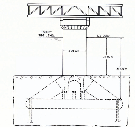
Fig. 2. Cook Inlet monopod platform with ice loads (from Blumberg and Strader, 1969).

Fig. 3. Details of sectional elevation and finite-element idealization.
Analysis
Equations of motion
The equations of motion for the tower, including hydrodynamic effects are written in terms of nodal coordinates as
where {u} is the nodal displacement matrix, [M], [C], [K] the mass (lumped structural mass), damping, and stiffness matrices respectively, {P (t)} the ice forces at various nodes, and {R (t)} the nodal loads associated with hydrodynamic pressures.
The axisymmetric tower, modelled as shown in Figure 3, is represented as an assemblage of quadrilateral toroid elements interconnected along nodal circles. The soil is broken into finite elements as shown in Figure 3(a); triangular elements have been used sparingly in order to have compatible displacement modes and to reduce the number of nodes (i.e. number of dynamic equations). The principal features of the finite-element analysis are given in the work reported by Reference Liaw and ChopraLiaw and Chopra (1973).
The hydrodynamic nodal loads are related to the accelerations of the outer surface of the tower, and hence modify the inertial properties of the structure. The normal modes of the tower without the surrounding water will not uncouple Equation (1), but can still be used to reduce the number of equations. The displacements of the tower including the effects of surrounding water are expressed in terms of the first F mode shapes as

in which Yj(t) is the generalized displacement, and {φj} the shape of the jth vibration mode of the tower (with no surrounding water), φjs are obtained as solutions of the eigenvalue problem,
where ωj is the jth vibration frequency (with no surrounding water).
Since these nodal hydrodynamic pressures act only at the outer surface of the tower, the elements in {R (t)} corresponding to the inner nodal circles are zero. The nodal hydro-dynamic pressures associated with (i) the circumferential (θ) and vertical (z) degrees of freedom of a vertical structure-water interface and (ii) all the three degrees of freedom of the nodal points above the water are zero. The jth decoupled equation of motion of Equation (1) obtained by the normal mode method (Reference Clough and PenzienClough and Penzien, 1975, p. 191-207) is
in which

where ζj is the modal damping ratio and {φjf} are the modal vectors associated with the hydrodynamic interaction.
The hydrodynamic loads are related to the accelerations of the outer surface of the tower. Neglecting the compressibility of water and the effect of surface waves, the hydrodynamic pressures on the tower are expressed as

Hence, the hydrodynamic force matrix (R(t)} is written (when θ=0) as

Introducing Equation (6) into Equation (4) and rearranging, the modal equations of motion in matrix form are written as
where
The matrix [B], known as the added water-mass matrix, is due to the interaction of the surrounding water with the tower. These quantities are obtained by solving the wave equation governing the dynamics of compressible fluids, subject to appropriate boundary conditions. For cylindrical towers, they can be obtained as closed-form solutions of the boundary value problem. For more complex shapes with non-vertical outside surfaces, the finite-element method can be used for the fluid medium to solve the equations. The small amplitude, irrotational motion of a compressible fluid is governed by the wave equation
in which p(r, z, θ, t) is the hydrodynamic pressure (in excess of hydrostatic pressure), and c is the velocity of sound in water. For water the compressibility could be neglected. Since the portion of the tower in contact with water is cylindrical and circular in plan, Equation (9) could be solved explicitly. The hydrodynamic pressure terms are (Reference Liaw and ChopraLiaw and Chopra, 1973).

where

K 0(λm′r0), K 2, (λm′r0) are modified Bessel functions of the second kind, w is the specific weight of water, g the acceleration due to gravity, r 0 the outer radius of the partly submerged cylinder, H the height of the submerged portion of the cylindrical tower, and ej(z) the continuous analogue of {φjf} given in Equation (4).
Only the radial accelerations of the outside surface of the tower need to be considered in the above solutions, since the circumferential and vertical motions of the tower do not produce any hydrodynamic pressures if water is treated as an ideal fluid. Substitution of Equation (10) into Equation (4) gives the added water mass in the modal of motion. The frequencies of the tower-water system are approximately obtained as
Generation of artificial ice-force records
Since records of ice force versus time are not available for such large structures, artificial ice-force records are generated as explained below. The method makes use of the similarity between the randomly oscillating ice-force records and seismic records to generate the ice-force records.
Available field measurements of continuous ice forces by Reference PeytonPeyton (1968[a]), Reference BlenkarnBlenkarn (1970), (Reference NeillNeill[1971], [1972], unpublished), and Reference SchwarzSchwarz (1970, Reference Schwarz[1971]) indicate resemblance to random time functions. The force variations are aperiodic and highly oscillatory about a varying mean force. Once the trend is removed, the ice-force records are similar to seismic records. The randomly oscillating part of an ice force record builds up from small amplitudes to a certain intensity that satisfies the stationarity condition for some time and then decays steadily.
The simulation of ice-force records can be satisfactorily achieved with a stationary process for the maximum response of a linear, well-damped system with a single degree of freedom, However, for systems with low damping as well as those which are non-linear or have many degrees of freedom the effect of non-stationarity becomes important when the main factor to be considered is the energy dissipated in plastic deformation of ice. The method detailed herein uses a non-stationary random process obtained from filtering a shot noise through a second-order linear filter. Both the filter and the shot noise are selected so that the artificial ice-force records generated will, on average, resemble the most relevant features of the records obtained when relatively strong ice sheets impact off-shore structures. In passing it must be noted that the ice-sheet strength is a function of temperature, ice structure, brine volume porosity, and rate of loading.
The second-order linear filter is simulated by the physical model of ice shown in Figure 4. The governing differential equation is
where ai(t) is the acceleration of the ice before impacting the structure, and ![]() the interactive acceleration at the ice-structure interface (
the interactive acceleration at the ice-structure interface (![]() times unit mass is the ice force on the structure).
times unit mass is the ice force on the structure).
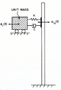
Fig. 4. Transfer-Junction model for randomly-fluctuating tee loading.
This equation is referred to as a second-order linear filter due to its analogue in electrical circuits. The details of the theory associated with the artificial generation of random ice-force records are given in the report of Reference Ruiz. and PenzienRuiz and Penzien (1969). The filter parameters ω0 and ζ, and the variance intensity function p(t) that governs the acceleration function ai(t), are estimated using the available ice-force records of Reference BlenkarnBlenkarn (1970) shown in Figure 5. The records are divided by unit mass, the constant means removed, and the fluctuating parts normalized to unit spectral intensities (Reference HousnerHousner, 1959). The estimation of w0, ζ and ρ(t) is done in the frequency domain and transformed back into the time domain. Also, since it is not possible to determine the distribution of the estimators, the estimated quantities are considered to be true values of the parameters. The estimates are obtained using a Hewlett-Packard Fourier Analyser.

Fig. 5. Blenkarn’s ice-force records (approximate velocity of ice flow = 1 m/s).
The values of ω0 and ζ that give the best fit with the available field records are ω0 = 1.23 Hz and ζ = 0.22, as shown in Figure 6. The variance intensity function is obtained as indicated in Figure 7; the sharp irregularities in the curve due to the reduced number of samples are smoothed out as shown. The constants t 0, p 0 and c are assumed to be t 0 = T—3 s, p a = 5.1 X 10⁻⁵ and c = 50, where T is the total duration of the ice-force record. The durations of the ice-force records are governed by the lengths and velocities of the ice-floes traversing the structure. Moreover, the expected maximum deviation of the ice force from the mean is found to be a function of temperature, previous thermal and stress history, porosity and brine volume. In this study the deviations arc assumed to be 20% to 40% of the mean.

Fig. 6. Filter characteristics.

Fig. 7. Variance intensity function.
The numerical procedure used for generating records is as follows: First, samples of a white noise with flat spectral densities of power are generated with random numbers (of uniform distribution) in the range (0 → 1) with time intervals Δτ. The white noise is multiplied by a shaping function ρ(t) to get the desired intensity. The time spacing Δτ gives an indication of the frequency variation in the generated ice-force records. In this study the chosen time spacings are 0.025, 0.037 5 and 0.050 s. These waveforms are passed through a second-order linear filter to obtain the interactive ice accelerations (and hence the ice-force records). Base-line corrections are made to let the interactive ice accelerations tend to zero at the end of the process.
In estimating the varying mean of the ice-force records, the actual field ice-cover measurements of Reference Bilello and BatesBilello and Bates (1971, Reference Bilello and Bates1975) are incorporated in the formula suggested by Reference Chakrabarti and ChopraAfanas’yev (1972). Afanas’yev’s formula for the maximum ice-force developed when an ice cover is cut through by the vertical column of the tower is
where m is the shape coefficient, equal to 0.90 for a semi-circle, k = [(5h/B) +1]1/2 for 1 ≤ B/h ≤ 6, [for B|h 1,the values are to be obtained from his graph], B is the width of the resisting structure, h the thickness of the ice sheet, and σ0 the uniaxial compressive strength of ice.
The uniaxial compressive strengths of ice are assumed to be 1 380, 1 724 and 2 069 kN/m2. The ice thickness profile used in this analysis is given in Figure 8 and the artificially generated ice-force records in Figures 9 and 10.

Fig. 8. Thickness profile of an ice-floe.
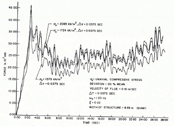
Fig. 9. Typical artificially generated ice-force records (amplitude variation)
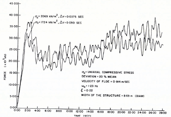
Fig. 10. Typical artificially generated ice-force records (amplitude and frequency variation).
Response
The ice-force record used in the determination of the dynamic responses is given in Figure 11; a shorter length of the ice-force record is considered to reduce the computation time. As mentioned before, the relevant portions of the SAP IV response history analysis arc isolated from the main programme to constitute a separate programme. The dynamic analysis is carried out using this segmented programme. The decoupled equations of motion are integrated by using Reference WilsonWilson’s (1972)θ-method which is an unconditionally stable integration scheme.

Fig. 11. Ice forces acting on the structure.
Results and Discussion
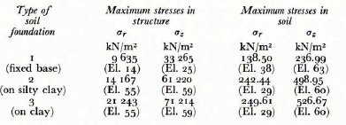
The tower is modelled as an axisymmetric structure and the restraint provided by the piles is simulated by restraining the conical base of the bottom of the tower against lift while allowing horizontal movement. The material of the tower is steel with a modulus of elasticity, E = 2 000 kN/m2. In order to account for the circumferential and axial stiffeners present in the vertical cylindrical shell, the structure is assumed to be homogenously orthotropic. The soil properties for silty clay are assumed to be as given by (Reference RichartRichart and others 1970, p. 354). In order to determine the influence of the soil properties on the structural frequencies and responses, a different set of soil properties was assumed for a second computation. The assumed soil and structural properties are given in Table I. The deck structure is replaced by concentrated masses (loads) at the nodal points as indicated in Table II.
TABLE I. PHYSICAL PROPERTIES OF THE TOWER-SOIL SYSTEM

TABLE II. ADDED MODAL MASSES

The maximum static stresses due to self weight, deck loads and water pressure are presented in Table III. The influence of the elasticity of the foundation on the structural/soil stresses appears significant. Stress redistributions occur as a result of the yielding foundation; the maximum stress in the tower with a clay foundation is found to be more than twice that for a fixed-base tower.
TABLE III. STATIC STRESSES DUE TO SELF WEIGHT, DECK LOADS AND WATER PRESSURE
[Refer Figure 3]
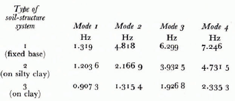
Figures 12 and 13, and Table IV summarize the influence of the soil properties on the frequencies of the structure. The frequencies of the tower—soil system are given in Table IV and the modal shapes in Figures 12 and 13. Soil-structure interaction decreases the frequencies of the structure; for the soil properties considered in this study, even in the fundamental frequency the change is 31.21% from that for a fixed-base tower. This finding seems to be contrary to an earlier observation made by Reference KhannaKhanna (1969) that the fundamental frequencies are not very sensitive to changes in soil properties. For higher frequencies the differences between corresponding values are much higher. This calls for rigorous modelling of the soil media beneath the structure to get better estimates of the structural response.

Fig. 12. Modal shapes of the tower on silty clay.

Fig. 13. Modal shapes of the tower on day.
TABLE IV. FREQUENCIES OF THE SOIL-STRUCTURE SYSTEM
The dynamic response of the tower for both the assumed soil properties is given in Figure 14. The dynamic deflections are observed to be more than twice the static deflection of 0.079 3 m reported by Blumberg and Strader (1969). As seen from Table V, the dynamic magnification factor for the force record given in Figure 11 is found to be 1.89 for a tower with fixed base; but the factor may be found to be higher if a larger length of record with numerous peaks is processed, and if the peak force occurs farther from the initial build-up period. The ratio η, between the dynamic deflections of the actual and the average force records is less than 1 since the force record given in Figure 2 has only a single peak in the initial build-up period of forces.

Fig. 14. Dynamic displacements in structure and soil.
TABLE V. RATIO OF DEFLECTIONS OF THE STRUCTURE
Static deflection =0.0741 m
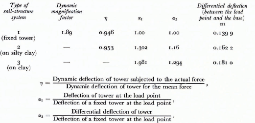
Table VI shows the effect of modification of the force record (Fig. 11) on the tower response. The dynamic magnification factor and the differential deflection coefficient α2 change from 1.89 to 2.99 and 1.00 to 1.585 respectively. This is a reasonable quantitative indication of the influence of the frequency content of the forcing functions. It can also be observed from Table V that the magnification factor is dependent on the soil properties of the foundation. It is therefore hardly necessary to stress the considerable need for more studies of this nature to evaluate the adequacy of recent code specifications for ice forces on structures.
TABLE VI. INFLUENCE OF THE FORCE-TIME RECORD ON DEFLECTION OF THE TOWER
The method formulated in the paper, for the generation of artificial ice-force records, gives realistic estimates of dynamic ice forces imposed on off-shore structures. By the proper choice of the ice-floe thickness variation shown in Figure 8 and the other parameters of the ice-force generation model, a combination of force situations contributing to the largest magnification factor can be obtained. The in-built design safety factor for the worst possible case can thus be obtained with better accuracy by using artificially generated force records.
Acknowledgements
The support of the investigation by Imperial Oil Co. Grant No. 04-2026 and N.R.C. Grant No. A8119 is gratefully acknowledged. The authors wish to express their gratitude to Dr R. T. Dempster, Dean of the Faculty of Engineering and Applied Science, and Dr A. A. Bruneau, Vice-President of Professional Schools and Community Services, Memorial University of Newfoundland, St. John’s, Newfoundland, for their keen interest and encouragement. Thanks are due to Professor D. Dunsiger for very valuable discussions on spectral analysis and the use of the Hewlett Packard 5451B Fourier Analyser.
Discussion
J. SCHWARZ: AS we know from Peyton’s test records, the highest ice pressure occurs just before the ice-floe comes to rest. In this case no further oscillations occur. How do you consider this case?
D. V. REDDY: The ice conditions in Cook Inlet, Alaska, over several seasons indicated successive impact by ice-floes with fairly constant velocities. Peyton’s records showed a clear “ratcheting” phenomenon establishing the validity of the ice model of Reference MatlockMatlock and others (1971) consisting of elastic-plastic vertical cantilevers mounted on a rigid base. A flexible structure is deformed by the impacting ice-floe and successive impacts will subject it to oscillation. Other ice environments may produce different kinds of response but these need to be studied.


