Hostname: page-component-cd9895bd7-8ctnn Total loading time: 0 Render date: 2024-12-29T07:56:58.537Z Has data issue: false hasContentIssue false

Close-contact melting of shear-thinning fluids

Published online by Cambridge University Press:  28 July 2023

Nan Hu
Affiliation:
Key Laboratory of Clean Energy and Carbon Neutrality of Zhejiang Province, Zhejiang University, Hangzhou 310027, PR China State Key Laboratory of Clean Energy Utilization, Zhejiang University, Hangzhou 310027, PR China Institute of Thermal Science and Power Systems, School of Energy Engineering, Zhejiang University, Hangzhou, Zhejiang 310027, PR China
Li-Wu Fan*
Affiliation:
Key Laboratory of Clean Energy and Carbon Neutrality of Zhejiang Province, Zhejiang University, Hangzhou 310027, PR China State Key Laboratory of Clean Energy Utilization, Zhejiang University, Hangzhou 310027, PR China Institute of Thermal Science and Power Systems, School of Energy Engineering, Zhejiang University, Hangzhou, Zhejiang 310027, PR China
*
Email address for correspondence: [email protected]

Abstract

This study aims at establishing a model for close-contact melting (CCM) of shear-thinning fluids. We presented a theoretical framework for predicting the variation of liquid melt film thickness and motion of unmelted solid for both Carreau and power-law fluids. We identified the appropriate energy equation considering the convective effect and derived an analytical temperature profile across the liquid film. Using the lubrication approximation, force equilibrium relationships and the corresponding numerical approaches were built. By using laser interferometry and photographic recording methods, we found excellent agreement between numerical solutions and experimental results for Carreau liquids, revealing that the convective effect weakens heat transfer and melting rate. We identified the critical liquid film thickness that determines three situations of CCM in the theoretical model for Carreau fluids. Numerical prediction demonstrated that the CCM of Carreau fluids can be almost equivalent to that of power-law fluids if the initial film thickness is greater than the critical value. Finally, approximate analytical models were developed for both Carreau and power-law models. For the applicability of the approximate analytical solutions, we derived two- and three-dimensional dimensionless phase diagrams of validity range and identified a key dimensionless group $(\varLambda Re)^{4/3}{Re}\left [3\ln (Ste+1)\right ]^{1/3}{Pe}^{-1/3}$, where $\varLambda$ is dimensionless characteristic time, Re is Reynolds number, Ste is Stefan number and Pe is Peclect number. The reliability of the approximate solutions was verified by comparing with the numerical results. These approximate solutions enable convenient and low-cost computational prediction of the dynamic CCM process of shear-thinning fluids.

Type
JFM Papers
Copyright
© The Author(s), 2023. Published by Cambridge University Press

1. Introduction

Over a wide range of melting phenomena, there is a special process called close-contact melting (CCM), where the unmelted solid surface and the heating surface are squeezed towards each other to maintain a close-contact status under the exertion of an external force. Unlike common convection melting in an expanding space involving Rayleigh–Bénard systems (Esfahani et al. Reference Esfahani, Hirata, Berti and Calzavarini2018), a sub-millimetre molten film remains between the unmelted solid and heating surfaces during CCM (Hu et al. Reference Hu, Zhang, Zhang, Liu and Fan2019), leading to a low-Reynolds-number film flow with solid–liquid phase change heat transfer. The CCM can be classified into two modes, i.e. heat source driven and unmelted solid driven, depending on the objective of the exerted force (Hu et al. Reference Hu, Li, Xu and Fan2022). The former mode usually represents the formation of a melting channel with a heating surface driven by a constant or an artificially set force through the solid to be melted, which occurs in magma migration (Marsh Reference Marsh1978), ‘self-burial’ (Chen, Hao & Chen Reference Chen, Hao and Chen2013) or ‘meltdown’ (Emerman & Turcotte Reference Emerman and Turcotte1983) in nuclear engineering, subtractive machining (Mayer & Moaveni Reference Mayer and Moaveni2008) and ice drilling (Schuller, Kowalski & Raback Reference Schuller, Kowalski and Raback2016). The latter mode, on the other hand, implies that the unmelted solid is extruded by its own weight onto the heating surface under gravity, which can be found in scenarios like the onset of glacier tables (Henot, Plihon & Taberlet Reference Henot, Plihon and Taberlet2021) and latent heat thermal energy storage (Kozak, Rozenfeld & Ziskind Reference Kozak, Rozenfeld and Ziskind2014) using solid–liquid phase change materials (PCMs), although the sinking process of the unmelted solid may be enhanced by an external force (Fu et al. Reference Fu, Yan, Gurumukhi, Garimella, King and Miljkovic2022).

The previous investigations on heat source-driven CCM have mainly been focused on prediction of the source migration rate. Moallemi and Viskanta measured experimentally the descending velocity of a heated tube at constant surface heat flux (Moallemi & Viskanta Reference Moallemi and Viskanta1985) and concluded that conduction is the dominant heat transfer mechanism during this process. A correlation of the dimensionless heat source velocity (${Pe}$, Pélect number) with the degree of superheat (${Ste}$, Stefan number) and the imposed excess force ($\Delta P$) was given as ${Pe} \sim {Ste}^{3/4} \Delta P^{1/4}$ (Bejan Reference Bejan1992). Then various situations were considered for CCM, e.g. on a surface with arbitrary shape (Fomin, Wei & Chugunov Reference Fomin, Wei and Chugunov1995), through an unmelted solid with power-law viscosity at the liquid phase (Fomin, Saitoh & Chugunov Reference Fomin, Saitoh and Chugunov1997) and with spatially varying heat flux (Schueller & Kowalski Reference Schueller and Kowalski2017).

In contrast, unmelted solid-driven CCM is more complicated due to the coupling effect between the imposed force (i.e. weight of the unmelted solid) and melting rate that are both time dependent. Especially, when CCM occurs at the bottom of a container (except for ice melting where the unmelted solid will float on the top), it is usually accompanied by natural convection within the upper region of the container. Since it has been confirmed that convection melting cannot be neglected at large ${Ste}$, as compared with CCM, in spherical (Moore & Bayazitoglu Reference Moore and Bayazitoglu1982), rectangular (Dong et al. Reference Dong, Chen, Wang and Ebadian1991) or cylindrical (Sparrow & Geiger Reference Sparrow and Geiger1986) vessels, numerous efforts have been devoted to studying CCM on a horizontal plate to focus on the flow and heat transfer within the thin liquid film. Saito et al. studied CCM of ice and octadecane cylinders on an isothermal horizontal surface (Saito et al. Reference Saito, Utaka, Akiyoshi and Katayama1985a,Reference Saito, Utaka, Akiyoshi and Katayamab). Both experimental and numerical results indicated that non-dimensional mean heat flux is proportional to the 1/4 power of the non-dimensional contact pressure, and that the temperature distribution across the liquid film deviates gradually from a linear profile for ${Ste} > 0.1$. Yoo et al. estimated this temperature profile deviation based on the non-dimensional interfacial temperature gradient predicted by magnitude analysis, showing discrepancies of less than 10 % at ${Ste} = 0.1$ and an exponential deviation when ${Ste} > 0.1$ (Yoo, Hong & Kim Reference Yoo, Hong and Kim1998). Moallemi et al. also carried out a similar study of this problem and gave a theoretical formula about the non-dimensional height of the unmelted solid by assuming a steady liquid film thickness and a quadratic polynomial temperature profile (Moallemi, Webb & Viskanta Reference Moallemi, Webb and Viskanta1986). Groulx & Lacroix established a three-dimensional transient model to predict the variation of liquid film thickness, and found that the effect of inertial force is negligible for high ${Pr}$ (Prandtl number) substances (Groulx & Lacroix Reference Groulx and Lacroix2007).

Although these prior studies have led to a basic understanding of unmelted solid-driven CCM phenomena, there is still a need for deeper insights into this problem when complex fluid behaviours of the molten substances are involved, e.g. the use of different types of PCM for thermal energy storage applications. Recently, Kozak et al. considered the CCM process with a PCM having non-Newtonian behaviour in its liquid phase, and derived an extended analytical model to predict the melt fraction and liquid film thickness (Kozak et al. Reference Kozak, Zeng, Al Ghossein, Khodadadi and Ziskind2019). Despite a good extension into the non-Newtonian regime, this new model has limitations because it was developed under the assumptions of a Bingham fluid of the liquid PCM (which is still a ‘linear’ rheological model with yield stress) as well as a linear temperature profile within the liquid film.

However, numerous studies on the rheological properties of various emerging PCMs have shown shear-thinning behaviours in their liquid phase, e.g. organic PCMs having long-chain molecular structures or composite PCMs filled with particles at relatively high loadings. For instance, Motahar et al. reported that n-octadecane with mesoporous silica particles (3 % or 5 % mass fraction) exhibits a distinct shear-thinning feature at shear rates ${<}50\ {\rm s}^{-1}$ (Motahar et al. Reference Motahar, Nikkam, Alemrajabi, Khodabandeh, Toprak and Muhammed2014). Sugar alcohols, a family of polyols derived from sugars and having great potential for thermal energy storage in the low-to-medium-temperature range ($80\unicode{x2013}250\,^{\circ }{\rm C}$) (Shao et al. Reference Shao, Chen, Yang, Ku and Fan2019; Shao et al. Reference Shao, Yang, Chen, Fan and Yu2021), also exhibit complex shear-thinning behaviours over a wide span of shear rates from $0.001$ to $1000\ {\rm s}^{-1}$. As far as the authors are aware, the unmelted solid-driven CCM process with a shear-thinning fluid has not yet been studied, either theoretically or experimentally, in the available literature, although this case is deemed to be of potential interest for important applications like thermal energy storage towards a decarbonized energy future.

Therefore, this work presents the derivation of a theoretical model for axisymmetric CCM on an isothermal horizontal surface, where the shear-thinning behaviour of the fluids (liquid PCMs) is described by two classical rheological models, i.e. power-law model and Carreau model, and the nonlinear temperature distribution within the liquid film is considered. Accurate numerical solutions and approximate analytical solutions are both obtained and validated by comparison with experimental results. The shear-thinning and convective effects on the dynamic process and heat transfer of CCM are investigated and discussed.

2. Physical model and theoretical framework

A typical axisymmetric CCM process is analysed as sketched in figure 1, where a cylindrical solid bulk PCM with radius $R$ and initial height $H(t=0) = {H}_{0}$ is heated from below by an isothermal horizontal plate at temperature ${T}_{w}$. The solid PCM maintains an initial temperature equal to its melting point ${T}_{m}$ ($< T_{w}$), so it will continuously melt from the bottom and squeeze the molten liquid consequently due to the weight of solid PCM, leading to a melt film with thickness ${\delta }$. It should be emphasized that the schematic diagram is not drawn to realistic scale (${\delta } \ll R \sim {H}_{0}$) according to the thin film approximation validated in all previous studies. Here, and in what follows, the quantities with hat ($\bar {.}$) are non-dimensionalized.

Figure 1. Schematic illustration of the flow and heat transfer in the axisymmetric CCM region having radius $R$ and thickness $\delta$, where $R \gg \delta$ and $H(0)/R$ is arbitrary.

2.1. Rheological model

A number of empirical expressions have been used to describe variations in the apparent viscosity with the rate of strain. In a generalized incompressible Newtonian fluid the viscous stress is described by

(2.1)\begin{equation} {\boldsymbol{\tau}}=2{\mu}{\boldsymbol{\varGamma}}={\mu}[\boldsymbol{\nabla} {\boldsymbol{u}}+(\boldsymbol{\nabla} {\boldsymbol{u}})^{\mathrm{T}}], \end{equation}

where ${\boldsymbol {\varGamma }}$ is the rate of strain tensor and apparent viscosity ${\mu }={\mu }{({\varGamma })}$; ${\varGamma }$ is the second invariant and equal to $\sqrt {\frac {1}{2} (\boldsymbol {\varGamma }\boldsymbol {:}\boldsymbol {\varGamma }})$. A well-known shear-thinning model is proposed as the Carreau–Yasuda model

(2.2)\begin{equation} \frac{{\mu}-{\mu}_{\infty}}{{\mu}_{0}-{\mu}_{\infty}}=[1+(2{\lambda}{\varGamma})^{a}]^{b}, \end{equation}

where ${\mu }_{\infty }$ is the viscosity at high shear rates $\dot {\gamma } = 2{\varGamma } \to \infty$, ${\mu }_{0}$ is the viscosity at low shear rates $2{\varGamma } \to 0$, ${\lambda }$ is a characteristic time of the fluid and $a$ and $b$ are characteristic parameters. It is worth noting that several widely used rheology constitutive models can be obtained by modifying conveniently the parameters in (2.2). When $a = 2$ and $b = (n-1)/{2}$, the Carreau model can be obtained as $\mu =\mu _{\infty }+(\mu _{0}-\mu _{\infty })[1+(2{\lambda }{\varGamma })^{2}]^{(n-1)/{2}}$. If $a=1-n$ and $b=-1$ are satisfied, it leads to the Cross model: $\mu =\mu _{\infty }+(\mu _{0}-\mu _{\infty })[1+(2{\lambda }{\varGamma })^{1-n}]^{-1}$. The power-law model $\mu \approx \mu _{0} (2 \lambda {\varGamma } )^{n-1}$ can be derived by setting $a=1, b=n-1$ under the conditions of $2{\lambda }{\varGamma } \gg 1$ and $\mu _{0} \gg \mu _{\infty }$. The Bingham model of $\mu = \mu _{0} + \tau _{0}/(2{\varGamma })$, which has been used and investigated in the CCM scenario by Kozak et al. (Reference Kozak, Zeng, Al Ghossein, Khodadadi and Ziskind2019), is established when $a=b=-1$ and $\lambda (\mu _{0}-\mu _{\infty })=\tau _{0}$.

Among the above models, the Carreau model (drawn in figure 2a) is widely used to describe shear-thinning fluids because it can correctly predict the viscosity at both low and high shear rates (Nouar, Bottaro & Brancher Reference Nouar, Bottaro and Brancher2007; Chekila et al. Reference Chekila, Nouar, Plaut and Nemdili2011; Agbessi et al. Reference Agbessi, Alibenyahia, Nouar, Lemaitre and Choplin2015), and it is in better agreement with experimental results (Allouche et al. Reference Allouche, Botton, Millet, Henry, Dagois-Bohy, Guzel and Ben Hadid2017; Boyko & Stone Reference Boyko and Stone2021). Although the prediction of the power-law model significantly deviates at high and low shear rates (as shown in figure 2b), the simplicity of the model still makes it very attractive to describe shear-thinning fluids when the operating shear rates lie in the range of power-law region (Kumar et al. Reference Kumar, Zuri, Kogan, Gottlieb and Sayag2021). Here, figure 2(c) shows five PCMs with different shear-thinning rheological properties in their liquid phase. It can be found that the curves are more in line with the Carreau model, but there is a considerable range that can be well described by the power-law model. Consequently, both the Carreau model and power-law model are adopted in the following analysis.

Figure 2. Theoretical prediction of viscosity for (a) Carreau model and (b) power-law model, where the dashed line represents the baseline at $\mu _{0}=100\ {\rm Pa}\ {\rm s}$, $n=0.2$, $\lambda =100$ s and $\beta = 0.001$. (c) Measured viscosity of selected shear-thinning fluids of liquid PCMs including pure sugar alcohols (inostitol, dulcitol and xylitol (Shao et al. Reference Shao, Yang, Chen, Fan and Yu2021)) and eutectic sugar alcohols (erythritol $+$ d-mannitol and d-mannitol $+$ inositol (Shao et al. Reference Shao, Chen, Yang, Ku and Fan2019)).

2.2. Governing equations and dimensionless parameters

By distances scaled with $R$, pressure and stresses with $\rho _{s} g H_{0}$ and time with $R/\sqrt {\rho _{s} g H_{0}/\rho _{l}}$, the incompressible flow governing equations in dimensionless form are given by

(2.3)$$\begin{gather} \boldsymbol{\nabla} \boldsymbol{\cdot} \bar{\boldsymbol{u}} = 0, \end{gather}$$
(2.4)$$\begin{gather}\frac{\partial \bar{\boldsymbol{u}} }{\partial \bar{t}}+(\bar{\boldsymbol{u}} \boldsymbol{\cdot} \boldsymbol{\nabla}) \bar{\boldsymbol{u}} ={-}\boldsymbol{\nabla} \bar{P}+ \boldsymbol{\nabla}\boldsymbol{\cdot} \bar{\boldsymbol{\tau}}, \end{gather}$$

where $\bar {\boldsymbol {u}}=\bar {u}_{r}\boldsymbol {{e}_{r}}+ \bar {u}_{z}\boldsymbol {{e}_{z}}$ denotes the fluid velocity, $\bar {P}$ the pressure (including gravity effect) and $\bar {\boldsymbol {\tau }}$ the viscous stress tensor. The melt film is supposed to be purely viscous as described by

(2.5)\begin{equation} \bar{\boldsymbol{\tau}}=\frac{1}{Re} 2\bar{\mu}({\varGamma})\bar{\boldsymbol{\varGamma}}, \end{equation}

where ${Re}$ is the Reynolds number, defined as

(2.6)\begin{equation} {Re} \equiv \frac{{R}\sqrt{\rho_{s} g H_{0}\rho_{l}} }{{\mu}_{0}}. \end{equation}

By introducing dimensionless temperature $\bar {T} = ( T- {T}_{m})/({T}_{w}-{T}_{m})$, the energy equation of flow considering viscous dissipation in dimensionless form is given by

(2.7)\begin{equation} \frac{\partial \bar{T}}{\partial \bar{t}} +\left (\bar{\boldsymbol{u}} \boldsymbol{\cdot} \boldsymbol{\nabla} \right ) \bar{T} = \frac{1}{Pe} \nabla^{2}\bar{T} +\frac{{Pr}{Ec}}{Pe}\bar{\boldsymbol{\varGamma}}:\bar{\boldsymbol{\varGamma}}, \end{equation}

where ${Pe}$ is the Péclet number, ${Pr}$ the Prandtl number and ${Ec}$ the Eckert number, which are defined respectively as

(2.8ac)\begin{equation} {Pe} \equiv \frac{ R {c}_{{p,l}} \sqrt{\rho_{s} g H_{0}\rho_{l}}}{ {k}_{l}},\quad {Pr} \equiv \frac{\mu}{\rho_{l}\alpha},\quad {Er} \equiv \frac{\rho_{s}gH_{0}}{\rho_{l}c_{{p,l}}({T}_{w}-{T}_{m})}, \end{equation}

with $\alpha, g, {k}_{l},{\rho }_{l}$ and ${c}_{{p,l}}$ being the thermal diffusivity, gravitational acceleration, thermal conductivity, density and specific heat capacity of the fluids, respectively.

As for the flow within the melt film, the following classical assumptions are adopted, consistent with previous works (Moallemi et al. Reference Moallemi, Webb and Viskanta1986; Kozak et al. Reference Kozak, Zeng, Al Ghossein, Khodadadi and Ziskind2019): (i) due to $R\gg \delta$, the lubrication approximation is valid for the melt film (i.e. $\partial / \partial z \gg \partial / \partial r$), (ii) the flow in the melt film is axisymmetric (i.e. $\partial / {\partial \theta } = 0$), laminar and in quasi-steady state (i.e. $\partial / {\partial t} = 0$), (iii) thermophysical properties are temperature independent, (iv) the bottom surface of the solid is flat (i.e. $\delta (t,r,\theta ) = \delta (t)$), (v) the temperature gradient in the $r$ direction is negligible, (vi) sensible heat of the melt liquid is neglected in heat transfer and (vii) viscous dissipation is negligible compared with the conductive term due to ${Pr}{Ec}\ll 1$ for most PCMs and thermal conditions. It is worth noting that the convective effect is here considered instead of the pure heat conduction simplification adopted by Kozak et al. (Reference Kozak, Zeng, Al Ghossein, Khodadadi and Ziskind2019).

Hence, the momentum equation (2.4) of fluid motion and the energy equation (2.7) can be described respectively by

(2.9ad)$$\begin{gather} \frac{\partial \bar{P}}{\partial \bar{r}}=\frac{\partial}{\partial \bar{z}}\left(\frac{1}{Re}\bar{\mu}({\varGamma}) \frac{\partial \bar{u}_{r}}{\partial \bar{z}}\right), \quad \frac{\partial \bar{P}}{\partial \bar{\theta}}=0, \quad \frac{\partial \bar{P}}{\partial \bar{z}}=0, \quad \text{with}\ {\varGamma}=\frac{1}{2}\left|\frac{\partial u_{r}}{\partial z}\right|, \end{gather}$$
(2.10)$$\begin{gather}\bar{u}_{z}\frac{\partial \bar{T}}{\partial \bar{z}}=\frac{1}{Pe} \frac{\partial^{2} \bar{T}}{\partial {\bar{z}}^{2}}. \end{gather}$$

Note that governing equations (2.9ad) and (2.10) imply $\bar {u}_{r}=\bar {u}_{r}(\bar {z}, \partial \bar {P}/\partial \bar {r})$, $\bar {P} = \bar {P}(\bar {r})$ and $\bar {T} = \bar {T}(\bar {z})$, respectively. Different from the pressure-driven flow (having a determinate pressure difference $\Delta P$ along the channel), the pressure gradient $\partial \bar {P}/\partial \bar {r}$ in the melt film stems from the extrusion of remaining solid bulk and is determined by force balance as

(2.11)\begin{equation} \int_{0}^{ R} 2{\rm \pi} r P\,\mathrm{d} r = \rho_{s} g{\rm \pi} R^{2}( H- \delta), \end{equation}

which can also be written in dimensionless form as

(2.12)\begin{equation} \int_{0}^{1} 2 \bar{r} \bar{P}\,\mathrm{d} \bar{r} = \frac{1}{A} (\bar{H}- \bar{\delta}), \end{equation}

where the aspect ratio $A = H_{0}/R$.

2.3. Force equilibrium relationship based on the power-law model

The constitutive expression of the power-law model for $\bar {\mu }$ is

(2.13)\begin{equation} \bar{\mu} =\frac{ \mu({\varGamma} )}{ \mu_{0}} \approx (2 {\lambda}{\varGamma} )^{n-1}=(\varLambda {Re} 2{\bar{\varGamma}})^{n-1}, \end{equation}

where $\varLambda$ is the ratio of the characteristic time of the fluid to the viscous diffusion time, which is fixed for a given fluid and flow length, as defined by

(2.14)\begin{equation} \varLambda = \frac{ \lambda}{ \rho_{l} R^{2}/\mu_{0}}. \end{equation}

By substituting (2.13) into (2.9ad) and integrating twice in two parts, i.e. $0-0.5\bar {\delta }$ and $0.5\bar {\delta }-\bar {\delta }$, for opposite velocity gradients with the boundary conditions of $\bar {u}_{r}|_{\bar {z}=0}=0$ and ${\partial \bar {u}_{r}}/{\partial \bar {z}}|_{\bar {z}=\bar {\delta }/2} = 0$ as well as $\bar {u}_{r}|_{\bar {z} =\bar {\delta }}= 0$ and ${\partial \bar {u}_{r}}/{\partial \bar {z}}|_{\bar {z}=\bar {\delta }/2} = 0$, respectively, the velocity profile for $\bar {z} = 0 -\bar {\delta }$ can be obtained as

(2.15) \begin{equation} \bar{u}_{r} = \frac{n}{1+n} \left(-\frac{\mathrm{d}\bar{P}}{\mathrm{d}\bar{r}}\right)^{1/n} \varLambda^{(1-n)/n}{Re}^{(2-n)/n} \Biggl[\left( \frac{\bar{\delta}}{2} \right)^{(1+n)/{n}} -\left | \bar{z}-\frac{\bar{\delta}}{2} \right |^{(1+n)/n}\Biggr]. \end{equation}

Then, integrating (2.3) along $\bar {z}$ with the boundary conditions of $\bar {u}_{z}|_{\bar {z}=0}=0$ and $\bar {u}_{z}|_{\bar {z}=\bar {\delta }}= ({\mathrm {d}(\bar {H} -\bar {\delta })}/{\mathrm {d} \bar {t}})({\rho _{s}}/{\rho _{l}}) +{\mathrm {d}\bar {\delta }}/{\mathrm {d} \bar {t}}$ yields

(2.16) \begin{align} \frac{1}{\bar{r}} \frac{\partial \Biggl[\left(-\dfrac{\mathrm{d}\bar{P}}{\mathrm{d}\bar{r}}\right)^{1/n}\bar{r}\Biggr]}{\partial \bar{r}} \frac{n}{1+n} \varLambda^{(1-n)/n}{Re}^{(2-n)/n} \int_{0}^{\bar{\delta}}\Biggl[ \left ( \frac{\bar{\delta}}{2} \right )^{({1+n})/{n}} -\left | \bar{z}-\frac{\bar{\delta}}{2} \right|^{(1+n)/n} \Biggr] -V^{{\ast} }=0, \end{align}

where ${V^\ast }=-\bar {u}_{z}|_{\bar {z}=\bar {\delta }}>0$ is related to the descending velocity of the solid bulk and thickening velocity of the melt film. Integrating (2.16) with respect to $r$ and applying the boundary conditions of $\mathrm {d}\bar {P}/\mathrm {d}\bar {r}|_{\bar {r}=0}=0$ and $\bar {P}|_{\bar {r}=1}=0$ yields

(2.17)\begin{equation} \bar{P}(\bar{r}) = \frac{(2n+1)^{n}(V^{{\ast}})^{n}}{(n+1)(4n)^{n}(\bar{\delta}/2)^{1+2n} \varLambda^{1-n}{Re}^{2-n}}(1-{\bar{r}}^{n+1}) . \end{equation}

Here, we can substitute (2.17) into (2.15) to obtain

(2.18) \begin{equation} \bar{u}_r=\frac{V^{{\ast}}}{\bar{\delta}^2} \frac{(2 n+1)}{(n+1)}\Biggl[\left(\frac{\bar{\delta}}{2}\right)-\left|\bar{z}-\frac{\bar{\delta}}{2}\right|\left|\frac{2 \bar{z}}{\bar{\delta}}-1\right|^{{1}/{n}}\Biggr] \bar{r}, \end{equation}

which indicates that $\bar {u}_r$ varies along both the $z$ and $r$ directions. Finally, substituting (2.17) into (2.12) and integrating lead to

(2.19)\begin{equation} \frac{2(2n+1)^{n}A}{(n+3)n^{n} \varLambda^{1-n} {Re}^{2-n}} \frac{(V^{{\ast}})^{n}}{{\bar{\delta}}^{1+2n}} = \bar{H}-\bar{\delta} . \end{equation}

2.4. Force equilibrium relationship based on the Carreau model

The constitutive description of the Carreau model for $\bar {\mu } ({\varGamma } )$ is given by

(2.20)\begin{equation} \bar{\mu}=\frac{ \mu}{ \mu_{0}}=\beta+(1-\beta)[1+(2 \lambda \mathit{ \varGamma})^{2}]^{(n-1) / 2},\end{equation}

where $\beta = \mu _{\infty }/ \mu _{0}$.

Note that it is difficult to get explicit expressions for the velocity profile $\bar {u}_{r}(\bar {z})$ via substituting (2.20) into (2.9ad), which implies that the pressure distribution $\bar {P}(\bar {r})$ cannot be obtained from integrating (2.3) without $\bar {u}_{r}(\bar {z})$. Thus, mass conservation in integral form, instead of differential form, should be used here to obtain the relationship between the flow rate $\bar {Q}$ and pressure gradient $\mathrm {d}\bar {P}/\mathrm {d}\bar {r}$. Although the solutions of governing equations (2.9ad) combined with (2.20) under the no-slip boundary condition have been similarly investigated in plane Poiseuille flow (Chekila et al. Reference Chekila, Nouar, Plaut and Nemdili2011) or approximate slit flow (Sochi Reference Sochi2015; Boyko & Stone Reference Boyko and Stone2021) of Carreau fluids, only asymptotic solutions or numerically solvable hypergeometric functions are currently available for a $Q-\Delta P$ (flow rate$-$constant pressure drop) relation, which fails to meet the demand of this problem but is inspiring.

We can refer to the transformation to avoid deriving the velocity profile by substituting (2.20) into (2.9ad), which yields

(2.21)\begin{equation} \bar{\tau} = \frac{1}{Re}[\beta+(1-\beta)(1+\varLambda^{2} {Re}^{2} {\bar{\dot{\gamma}}}^{2})^{(n-1) / 2}]\bar{\dot{\gamma}} \quad \text{with}\ \bar{\dot{\gamma}} = \frac{\partial \bar{u}_{r}}{\partial \bar{z}}. \end{equation}

According to the flow rate expression proposed by Sochi (Reference Sochi2015) and Wilkinson (Reference Wilkinson1972), the flow rate $\bar {Q}$ between two circular surfaces can be deduced from the shear stress $\bar {\tau }_{w}$, as given by

(2.22)\begin{equation} \frac{\bar{Q}}{\bar{\delta}^{2}{\rm \pi} \bar{r}} = \frac{1}{\bar \tau_{w}^{2}}\int_{0}^{\bar{\tau}_{w}}\bar{\tau} \bar{\dot{\gamma}}\,\mathrm{d}\bar{\tau}. \end{equation}

After integrating (see Appendix A for details), (2.22) becomes

(2.23) \begin{align} \frac{\bar{Q}}{\bar{\delta}^{2}{\rm \pi} \bar{r}} &= \frac{1}{3}\bar{\dot{\gamma}}_{w} \left\{\vphantom{\prod_{l=1}^{j}}1 - \frac{\beta(1-\beta)(1+\varLambda^{2} {Re}^{2} \bar{\dot{\gamma}}_{w}^{2})^{({n-1})/{2}}}{[\beta+(1-\beta)(1+\varLambda^{2} {Re}^{2} \bar{\dot{\gamma}}_{w}^{2})^{({n-1})/{2}}]^2}\right.\nonumber\\ &\quad \left.\times \sum_{j=1}^{\infty}\frac{(\varLambda^{2} {Re}^{2}\bar{\dot{\gamma}}_{w}^{2})^{j}}{(1+\varLambda^{2}{Re}^{2} \bar{\dot{\gamma}}_{w}^{2})^{j}} \prod_{l=1}^{j}\frac{2l-n-1}{2l+3} \right.\nonumber\\ &\quad \left. - \,\frac{\frac{1}{2}(1-\beta)^{2}(1+\varLambda^{2} {Re}^{2} \bar{\dot{\gamma}}_{w}^{2})^{n-1}}{[\beta+(1-\beta)(1+\varLambda^{2} {Re}^{2} \bar{\dot{\gamma}}_{w}^{2})^{({n-1})/{2}} ]^2} \sum_{j=1}^{\infty}\frac{(\varLambda^{2} {Re}^{2}\bar{\dot{\gamma}}_{w}^{2})^{j}}{(1+\varLambda^{2}{Re}^{2} \bar{\dot{\gamma}}_{w}^{2})^{j}} \prod_{l=1}^{j}\frac{2l-2n}{2l+3} \right\}. \end{align}

The results of $\bar {Q}/(\delta ^{2}{\rm \pi} \bar {r})$ along ${\bar {\dot {\gamma }}}_{w}$ under various $n$ and number of terms $j$ are depicted in figure 9 by numerically computing the series in (2.23). When ${\varLambda } {Re}{\bar {\dot {\gamma }}}_{w} \ll 1$, (2.23) can be simplified to

(2.24)\begin{equation} \frac{\bar{Q}}{{\bar{\delta}}^{2}{\rm \pi} \bar{r}} = \frac{1}{3} {\bar{\dot{\gamma}}}_{w}. \end{equation}

Furthermore, when $1 \ll {\varLambda } {Re}{\bar {\dot {\gamma }}}_{w} \ll \sqrt [1-n]{(1-\beta )/\beta }$, (2.23) can be written as

(2.25)\begin{align} \frac{\bar{Q}}{{\bar{\delta}}^{2}{\rm \pi} \bar{r}} &= \frac{1}{3}{\bar{\dot{\gamma}}}_{w} \left[1 - \frac{\beta(\varLambda {Re}{\bar{\dot{\gamma}}}_{w})^{1-n} }{1-\beta}\sum_{j=1}^{\infty } \prod_{l=1}^{j}\frac{2l-n-1}{2l+3}-\frac{1}{2}\sum_{j=1}^{\infty } \prod_{l=1}^{j}\frac{2l-2n}{2l+3} \right]\nonumber\\ & = \frac{1}{3}{\bar{\dot{\gamma}}}_{w} \left(1 -\frac{1}{2}\sum_{j=1}^{\infty } \prod_{l=1}^{j}\frac{2l-2n}{2l+3} \right) = \frac{1}{3}{\bar{\dot{\gamma}}}_{w} \mathcal{H}(n), \end{align}

where $\mathcal {H}(n) = 1 -\frac {1}{2}\sum _{j=1}^{\infty } \prod _{l=1}^{j}({2l-2n})/({2l+3})$.

As for ${\varLambda } {Re}{\bar {\dot {\gamma }}}_{w}\gg \sqrt [1-n]{(1-\beta )/\beta }$, (2.23) can be rewritten as

(2.26)\begin{align} \frac{\bar{Q}}{{\bar{\delta}}^{2}{\rm \pi} \bar{r}} &= \frac{1}{3}{\bar{\dot{\gamma}}}_{w} \left[1 - \frac{(1-\beta) }{\beta(\varLambda {Re}{\bar{\dot{\gamma}}}_{w})^{1-n} }\sum_{j=1}^{\infty } \prod_{l=1}^{j}\frac{2l-n-1}{2l+3}\right.\nonumber\\ &\quad \left.-\frac{1}{2}\frac{(1-\beta)^{2}}{\beta^2( \varLambda {Re}{\bar{\dot{\gamma}}}_{w})^{2-2n} }\sum_{j=1}^{\infty } \prod_{l=1}^{j}\frac{2l-2n}{2l+3} \right]. \end{align}

Notice that the last two terms in brackets of (2.26) are far less than 1. Hence, (2.26) can be simplified to

(2.27)\begin{equation} \frac{\bar{Q}}{{\bar{\delta}}^{2}{\rm \pi} \bar{r}} = \frac{1}{3}{\bar{\dot{\gamma}}}_{w}. \end{equation}

On the other hand, the unknown $\bar {\dot {\gamma }}_{w}$ is related to the pressure gradient $\mathrm {d}\bar {P}/\mathrm {d}\bar {r}$ as given by

(2.28) \begin{equation} \frac{1}{Re} [ \beta+(1-\beta)(1+\varLambda^{2} {Re}^{2} \bar{\dot{\gamma}}_{w}^{2})^{({n-1})/{2}}]\bar{\dot{\gamma}}_{w} = \bar{\tau}_{w} ={-}\frac{\mathrm{d}\bar{P}}{\mathrm{d}\bar{r}}\frac{\bar{\delta}}{2}. \end{equation}

Hence, the pressure gradient in asymptotic form can also be obtained after substituting $\bar {Q} =V^{\ast } {\rm \pi}{\bar {r}}^2$ into the expressions (2.24), (2.25) and (2.27), as given by

(2.29) \begin{align} -\frac{\mathrm{d}\bar{P}}{\mathrm{d}\bar{r}}\frac{\bar{\delta}}{2} = \begin{cases} \displaystyle\frac{1}{Re}\frac{3~V^{{\ast}}\bar{r}}{{\bar{\delta}}^2} & \text{if } 0<\bar{r}\ll \dfrac{{\bar{\delta}}^2}{3V^{{\ast}} \varLambda {Re}}, \\[12pt] \displaystyle\frac{1-\beta}{{Re}\left(\varLambda {Re}\right)^{1-n}}\Biggl(\dfrac{3~V^{{\ast}}\bar{r}}{{\bar{\delta}}^2 \mathcal{H}(n)}\Biggr)^{n} & \text{if } \dfrac{{\bar{\delta}}^2\mathcal{H}(n)}{3V^{{\ast}} \varLambda {Re}} \ll \bar{r}\ll \dfrac{{\bar{\delta}}^2\mathcal{H}(n)}{3~V^{{\ast}} \varLambda {Re}} \left(\dfrac{1-\beta}{\beta}\right)^{{1}/({1-n})},\\[12pt] \displaystyle\frac{\beta}{Re}\frac{3V^{{\ast}}\bar{r}}{{\bar{\delta}}^2} & \text{if } \bar{r}\gg \frac{{\bar{\delta}}^2}{3V^{{\ast}} \varLambda {Re}} \left(\dfrac{1-\beta}{\beta}\right)^{{1}/({1-n})}. \end{cases} \end{align}

Then, integrating (2.29) twice under asymptotic assumptions and substituting into (2.12) leads to two control equations (details are given in Appendix B), depending on whether the magnitude of the maximum shear rate at the radius edge reaches the high shear rate in the Carreau model . The two equations are defined as $\mathcal {MN}$ and $\mathcal {PQ}$ equation as follows. For the $\mathcal {MN}$ equation

(2.30)\begin{equation} \mathcal{M} \frac{{\bar{\delta}}^5}{\left(V^{{\ast}}\right)^3}+ \mathcal{N} \frac{\left(V^{{\ast}}\right)^n}{{\bar{\delta}}^{2n+1}}= \bar{ H} -\bar{\delta} \quad \text{for} \left(\frac{\beta}{1-\beta}\right)^{{1}/({1-n})} \leqslant \frac{{\bar{\delta}}^2}{3V^{{\ast}}\varLambda {Re} } \leqslant 1 , \end{equation}

where

(2.31)\begin{equation} \mathcal{M} = \frac{A}{27{Re}}\frac{1}{\left(\varLambda {Re}\right)^4} \left[ \frac{1}{2}-\frac{2\left(1-\beta\right)}{(n+3)\left(\mathcal{H}(n)\right)^n} \right], \end{equation}

and

(2.32)\begin{equation} \mathcal{N} = \frac{A}{Re}\frac{1-\beta}{\left(\varLambda{Re}\right)^{1-n}}\frac{2}{n+3}\left(\frac{3}{\mathcal{H}(n)}\right)^n. \end{equation}

For the $\mathcal {PQ}$ equation

(2.33)\begin{equation} \mathcal{P} \frac{{\bar{\delta}}^5}{\left(V^{{\ast}}\right)^3} + \mathcal{Q} \frac{V^{{\ast}}}{{\bar{\delta}}^{3}} = \bar{ H} -\bar{\delta} \quad \text{for} \left(\frac{\beta}{1-\beta}\right)^{{1}/({1-n})} \geqslant \frac{{\bar{\delta}}^2}{3V^{{\ast}}\varLambda {Re} } , \end{equation}

where

(2.34)\begin{align} \mathcal{P} &= \frac{A}{27{Re}}\frac{1}{\left(\varLambda {Re}\right)^4} \left[ \frac{1}{2}+\frac{-2}{n+3}\frac{(1- \beta)}{\left(\mathcal{H}(n)\right)^n} +\frac{2}{n+3}\frac{1-\beta}{\left(\mathcal{H}(n)\right)^n}\left(\frac{1-\beta}{\beta}\right)^{({3+n})/({1-n})} \right.\nonumber\\ &\quad \left. +\frac{-\beta}{2}\left(\frac{1-\beta}{\beta}\right)^{{4}/({1-n})}\right], \end{align}

and

(2.35)\begin{equation} \mathcal{Q} = \frac{3\beta}{2}\frac{A}{Re} . \end{equation}

Here, we denote

(2.36) \begin{align} \mathcal{B} &= \frac{1}{2}+\frac{-2}{n+3}\frac{(1- \beta)}{(\mathcal{H}(n))^n} +\frac{2}{n+3}\frac{1-\beta}{(\mathcal{H}(n))^n}\left(\frac{1-\beta}{\beta}\right)^{({3+n})/({1-n})}\nonumber\\ &\quad + \frac{-\beta}{2}\left(\frac{1-\beta}{\beta}\right)^{{4}/({1-n})} , \end{align}

and $\mathcal {P} = ({A}/{27{Re}})({\mathcal {B}}/{(\varLambda {Re})^4)}$ for ease of writing in the subsequent sections.

Furthermore, it is of interest to analyse expressions (2.30) and (2.33) in the limit of $2\lambda \varGamma \ll 1$ and $\beta = 0$ to compare with the power-law model in § 2.3. It can be easily known that the dimensionless form of limit $2\lambda \varGamma \ll 1$ is ${\varLambda }{Re}\bar {\dot {\gamma }}_w\gg 1$. With the limit of $\beta = 0$ and $\varLambda Re{\bar {\dot {\gamma }}_w}\gg 1$, (2.27) and (2.24) will become absent, which consequently leads to a transformation of (2.29) as

(2.37)\begin{equation} -\frac{\mathrm{d} \bar{P}}{\mathrm{d} \bar{r}} \frac{\bar{\delta}}{2}= \frac{1-\beta}{\mathit{Re}(\varLambda \mathit{Re})^{1-n}}\left(\frac{3 V^* \bar{r}}{\bar{\delta}^2 \mathcal{H}(n)}\right)^n \quad \text{for $0 \leqslant \bar{r} \leqslant 1$}. \end{equation}

Then, it can be found that the pressure distribution of the Carreau model in the limits of $\beta = 0$ and ${\varLambda }{Re}{\bar {\dot {\gamma }}_w}\gg 1$ is

(2.38)\begin{equation} \bar{P}(\bar{r}) = \frac{2(1-\beta)}{{Re}\left(\varLambda {Re}\right)^{1-n}}\left(\frac{3~V^{{\ast}}}{ \mathcal{H}(n)}\right)^{n}\frac{1}{{\bar{\delta}}^{2n+1}}\frac{1-{\bar{r}}^{n+1}}{n+1}, \end{equation}

which is equivalent to the pressure distribution (2.17) in the power-law model because $\mathcal {H}(n)={3n}/{(2n+1)}$ can be verified by numerical calculation.

Consequently, (2.30) is also equivalent to (2.19) because the term of $\mathcal {M}$ disappears when integrating (2.38). In summary, it is clear, as expected, that the Carreau model will be converged to the power-law model in the limit of $2\lambda \varGamma \ll 1$ and $\beta = 0$.

2.5. Temperature profile and energy equation at interface

Recall the energy equation (2.10) considering the convective effect, where ${\bar {u}}_{z}$ should be found to solve the temperature profile $\bar {T}(\bar {z})$ and temperature gradient $\mathrm {d} \bar T/\mathrm {d}\bar {z}$ at $\bar {z} =\bar {\delta }$. For a given ${\bar {u}}_r$, e.g. (2.15) for power-law fluids, ${\bar {u}}_z$ can be solved by integrating the continuity equation along the z direction, while it fails for Carreau fluids due to the absence of an explicit expression for ${\bar {u}}_r$. After evaluating different assumptions for ${\bar {u}}_z$ (see details in Appendix C), we can adopt the approximation $\bar {u}_{z}\sim \bar {u}_{z}|_{\bar {z}=\bar {\delta }}$ in (2.10), leading to

(2.39)\begin{equation} {-}{V^\ast}\frac{\partial \bar T}{\partial \bar{z}}=\frac{1}{Pe} \frac{\partial^{2}\bar{T}}{\partial {\bar{z}}^{2}}. \end{equation}

Then (2.39) can be theoretically solved with the boundary conditions

(2.40a,b)\begin{equation} \bar T(\bar{z}=0)=1, \quad \bar T(\bar{z}=\bar{\delta})=0. \end{equation}

The solution of the temperature profile over the melt film is given by

(2.41)\begin{equation} \bar{T}(\bar{z})= \frac{\exp({-V^\ast \bar{z} {Pe}}) -\exp({-V^\ast \bar{\delta} {Pe}}) }{1-\exp({-V^\ast \bar{\delta} {Pe}})}, \end{equation}

which implies that the temperature $\bar {T}(\bar {z})$ will gradually deviate from a linear distribution with increasing $V^{\ast }{Pe}$ that is related to the convection intensity.

The energy conservation equation at the solid–liquid interface is given by

(2.42)\begin{equation} {-}\left. k_{l} \frac{\partial T}{\partial z}\right|_{z= \delta}=\rho_{s} L \left( -\frac{\mathrm{d} H}{\mathrm{d} t}+ \frac{\mathrm{d} \delta}{\mathrm{d} t}\right), \end{equation}

where $L$ is the latent heat of fusion. The dimensionless form of (2.42) is

(2.43)\begin{equation} \left.-\frac{Ste}{\bar{\rho}{Pe}} \frac{\partial {\bar{T}}}{\partial {\bar{z}}} \right| _{\bar{z}=\bar{\delta}} ={-}\frac{\mathrm{d} \bar{ H}}{\mathrm{d} \bar{t}}+ \frac{\mathrm{d} \bar{\delta}}{\mathrm{d} \bar{t}}, \end{equation}

where $\bar {\rho } = \rho _{s}/\rho _{l}$ is the solid–liquid density ratio and the Stefan number ${Ste}$ is defined as

(2.44)\begin{equation} {Ste} \equiv \frac{ c_{{p, l}}\left( T_{w}- T_{m}\right)}{ L}. \end{equation}

Substitution of (2.41) into (2.43) yields the comprehensive expression for the transient velocity relationship with $\bar {\delta }^{\prime }(\bar {t})$ and $\bar {H}^{\prime }(\bar {t})$

(2.45)\begin{equation} \frac{Ste}{\bar{\rho}}\frac{V^{{\ast}}}{\exp({V^{{\ast}}\bar{\delta} {Pe}})-1}={-}\frac{\mathrm{d} \bar{ H}}{\mathrm{d} \bar{t}}+ \frac{\mathrm{d} \bar{\delta}}{\mathrm{d} \bar{t}}. \end{equation}

Considering the scaling of $({\mathrm {d} \bar {\delta } }/{\mathrm {d} \bar {t}}) ({\rho _{s}-\rho _{l}}/{\rho _{l}}) \ll - ({\mathrm {d}\bar {H} }/{\mathrm {d} \bar {t}} )({\rho _{s}}/{\rho _{l}})$, leads to

(2.46)\begin{equation} V^{{\ast}} ={-}\bar{\rho}\frac{\mathrm{d} \bar{ H} }{\mathrm{d} \bar{t}}. \end{equation}

Then, with the scaling of ${\mathrm {d} \bar {\delta } }/{\mathrm {d} \bar {t}} \ll - {\mathrm {d}\bar { H} }/{\mathrm {d} \bar {t}}$, (2.45) and (2.46) can be simplified respectively as

(2.47)\begin{equation} -\frac{\mathrm{d} \bar{ H} }{\mathrm{d} \bar{t}}=\frac{\ln({Ste}+1)}{\bar{\rho}{Pe} \bar{\delta}}, \end{equation}

and

(2.48)\begin{equation} V^{{\ast}}=\frac{\ln({Ste}+1)}{ {Pe} \bar{\delta}}. \end{equation}

Note that (2.47) can be written in the following Taylor expansion form:

(2.49)\begin{equation} {-} \frac{\mathrm{d}\bar{ H} }{\mathrm{d} \bar{t}} = \frac{\ln({Ste}+1)}{\bar{\rho}{Pe} \bar{\delta}} = \frac{1}{\bar{\rho}{Pe} \bar{\delta}}\sum_{i=0}^{\infty} \frac{({-}1)^i}{i+1} {Ste}^{i+1}. \end{equation}

This implies that (2.47) can be approximated to

(2.50)\begin{equation} {-}\frac{\mathrm{d} \bar{ H} }{\mathrm{d} \bar{t}}=\frac{Ste}{\bar \rho {Pe} \bar{\delta}} \quad \text{for} \ {Ste} \ll 1,\end{equation}

which is the pure conductive form consistent with previous studies (Kozak et al. Reference Kozak, Zeng, Al Ghossein, Khodadadi and Ziskind2019; Kozak Reference Kozak2022).

The relative deviation between (2.47) and (2.50) can be estimated by ${Ste}/\ln ({Ste}+1)-1$, resulting in an approximate deviation of $4.9\,\%$ for $Ste = 0.1$, $9.7\,\%$ for $Ste = 0.2$ and $23.3\,\%$ for $Ste = 0.5$. This estimation indicates that the assumption of pure heat conduction in the melt film will lead to an overestimated melting rate, especially at higher values of ${Ste}$.

3. Approaches to numerical solution

3.1. Numerical solution for the power-law model

By substituting (2.48) into (2.19), the following relation can be derived:

(3.1)\begin{equation} \frac{2(2n+1)^{n}}{(n+3)n^{n}} \frac{A}{ (\varLambda {Re})^{1-n} {Re}} \left[\frac{\ln({Ste}+1)}{Pe}\right]^n \frac{1}{ {\bar{\delta}}^{1+3n}} +\bar{\delta} = \bar{ H}. \end{equation}

Equations (2.47) and (3.1) comprise a set of first-order ordinary differential equations and nonlinear algebraic equations, respectively, that can be solved numerically. Equation (2.47) can be discretized using a forward Euler scheme as

(3.2)\begin{equation} \bar{ H}^{i+1} ={-} \frac{\ln({Ste}+1)}{\rho {Pe} \bar{\delta}^{i}} \Delta \bar{t} + \bar{H}^{i}, \end{equation}

where $i$ and $i+1$ denote the current and next time steps, respectively, and $\Delta \bar {t}$ is the discrete time step size.

The current film thickness $\bar {\delta }^{i}$ can be obtained via solving the following equation:

(3.3)\begin{equation} \frac{2(2n+1)^{n}}{(n+3)n^{n}} \frac{A}{ (\varLambda {Re})^{1-n} {Re}} \left[\frac{\ln({Ste}+1)}{Pe}\right]^n \frac{1}{ {(\bar{\delta} ^i)}^{1+3n}} +\bar{\delta} ^{i} = \bar{ H}^{i}. \end{equation}

The initial condition of $\bar { H}(\bar {t} = 0)$ is applied

(3.4)\begin{equation} \bar{ H}(\bar{t} = 0) = A. \end{equation}

At each time step, (3.3) is solved for $\bar {\delta }^{i}$ and then the new remaining height $\bar { H}^{i+1}$ is calculated via (3.2). Especially, for the first time step, $\bar {H}^{i} = A$ is set according to (3.4). The dimensional time step $\Delta t = 0.1$ s is adopted due to proper convergence and computational cost after performing an independence test of the time step size.

3.2. Numerical method for the Carreau model

First, we can find a turning condition from (2.30) to (2.33) as

(3.5)\begin{equation} \frac{\bar{\delta}^2}{3 V^* \varLambda {Re}}\left(\frac{1-\beta}{\beta}\right)^{{1}/({1-n})} = 1. \end{equation}

By substituting (2.48) into (3.5), a critical film thickness $\bar {\delta }_{cr}$ can be identified, as given by

(3.6) \begin{equation} \bar{\delta}_{cr} = \Biggl[ \frac{3\varLambda {Re} \ln({Ste}+1)}{Pe} \left(\frac{\beta}{1-\beta}\right)^{{1}/({1-n})}\Biggr]^{{1}/{3}}. \end{equation}

Essentially the critical liquid film thickness $\bar {\delta }_{cr}$ implies whether the wall shear rates $\bar {\gamma }_{w}$ at the outlet ($\bar {r} = 1$) reaches the plateau region for high shear rate in the Carreau model during the CCM process, which leads to the transition of the pressure distribution (i.e. transition from (B3) to (B9) as derived in Appendix B) and consequently determines the choice of $\mathcal {PQ}$ or $\mathcal {MN}$ equation.

Similarly, the following nonlinear relations can be obtained, respectively, via substituting (2.48) into (2.30) and (2.33):

(3.7)\begin{equation} \mathcal{M}\left[ \frac{Pe}{\ln({Ste}+1)}\right]^3{\bar{\delta}}^8 + \mathcal{N} \left[\frac{\ln({Ste}+1)}{Pe}\right]^n \frac{1}{{\bar{\delta}}^{2n+1}} +\bar{\delta} = \bar{H} \quad \text{for} \ \bar{\delta} \geqslant \bar{\delta}_{cr}, \end{equation}

and

(3.8)\begin{equation} \mathcal{P} \left[ \frac{Pe}{\ln({Ste}+1)}\right]^3{\bar{\delta}}^8 + \mathcal{Q} \frac{\ln({Ste}+1)}{Pe} \frac{1}{{\bar{\delta}}^{3}} +\bar{\delta} = \bar{H} \quad \text{for} \ \bar{\delta} \leqslant \bar{\delta}_{cr}. \end{equation}

Equation (3.2) is still utilized to calculate the height of solid PCM while the current thickness $\bar {\delta }^{i}$ is obtained via

(3.9)\begin{equation} \mathcal{M} \left[ \frac{Pe}{\ln({Ste}+1)}\right]^3({\bar{\delta}^i})^8 + \mathcal{N}\left[\frac{\ln({Ste}+1)}{Pe}\right]^n \frac{1}{({\bar{\delta}^i})^{2n+1}} +{\bar{\delta}^i} = \bar{ H} ^{i}, \end{equation}

or

(3.10)\begin{equation} \mathcal{P} \left[ \frac{Pe}{\ln({Ste}+1)}\right]^3{({\bar{\delta}^i})}^8 + \mathcal{Q} \frac{\ln({Ste}+1)}{Pe} \frac{1}{{({\bar{\delta}^i})}^{3}} +{\bar{\delta}^i} = \bar{ H} ^{i}. \end{equation}

Note that both (3.9) and (3.10) are solved for each time step to obtain $\bar {\delta }^{i}$ to compare with the critical value $\bar {\delta }_{cr}$. Subsequently, the $\bar {\delta }^{i}$ that meets the inequality requirement is adopted for consequent calculations. Also, the same initial condition (3.4) and time step $\Delta t = 0.1$ s are adopted for all cases.

As for determining the initial film thickness $\bar {\delta }(0)$, we first assume that the $\mathcal {PQ}$ equation is satisfied by substituting $\bar { H}(0) = A$ to solve (3.10). If the condition of $\bar {\delta }(0) \leqslant \bar {\delta }_{cr}$ is satisfied, it can be verified that the presumption is correct. If $\bar {\delta }(0) > \bar {\delta }_{cr}$, it means that the $\mathcal {PQ}$ equation is not satisfied and the initial value needs to be solved by the $\mathcal {MN}$ equation. Since the $\mathcal {PQ}$ and $\mathcal {MN}$ equations are equivalent when the liquid film thickness is exactly equal to the critical value, this a posteriori solution method to determine the initial film thickness will not cause errors.

4. Numerical results and experimental validation

4.1. Experimental set-up and procedure

4.1.1. Experimental apparatus

As shown in figure 3(a), a heated-from-below configuration was arranged by placing vertically a cylindrically shaped PCM sample on a heating plate. Two experimental devices were established to separately measure the instantaneous top surface height $H(t)$ of solid PCM and thickness $\delta (t)$ of melt film during CCM. The height $H(t)$ was recorded by a digital camera, whereas thickness $\delta (t)$ was obtained based on laser interference method similar to the measurement of the microlayer under vapour bubbles during boiling (Chen et al. Reference Chen, Hu, Hu, Utaka and Mori2020; Sinha, Narayan & Srivastava Reference Sinha, Narayan and Srivastava2021). Details of the experimental set-up and procedure for measuring height $H(t)$ and thickness $\delta (t)$ can be found in our previous work (Hu et al. Reference Hu, Zhu, Li, Tu and Fan2018, Reference Hu, Zhang, Zhang, Liu and Fan2019). Two heating boundary temperatures were used for each PCM corresponding to wall superheats $\Delta T$ of $10\,^{\circ }{\rm C}$ and $30\,^{\circ }{\rm C}$, respectively, in all cases. Given the slim shape of the PCM sample, it tended to tilt upon melting from the bottom. Hence, a glass tube having an inner diameter that is slightly greater than the outer diameter of the PCM column was suspended vertically to hold it as a guide, so as to prevent it from titling during each CCM run.

Figure 3. (a) Sketch of the experimental apparatus measuring the melt film thickness $\delta (t)$ and recording the height of the solid $H(t)$. (b) In-house measurements of viscosity as a function of strain rate of 1,6H/G-X1 % and T-X1 %, also included are data points for inositol and dulcitol (Shao et al. Reference Shao, Yang, Chen, Fan and Yu2021), where the shaded patches represent the scatter range of the measured viscosity. The regression to Carreau (blue lines) functions and fitting parameters are listed in table 1, and the power-law (red lines) functions are determined by using the same fitting parameters from the Carreau model.

During the measurement of $H(t)$, a three-way valve was used to trigger melting from the low-temperature loop to the high-temperature loop. The analysis ignored the little delay in the copper base's temperature response after switching the valve. To prevent heat losses to the environment, the entire arrangement was enclosed in a thermostat that was kept at the initial temperature of the PCM. During the melting process, the decreasing height of the PCM sample was captured by a digital camera every 5 s. The photos were then loaded into an image processing program to precisely calculate the height. A circumferentially grooved shape on the base allowed drainage of the liquid melt squeezed from the thin film.

As for measuring $\delta (t)$, experiments were carried out inside an acrylic reservoir that was utilized to collect molten PCM and serve as a confined environment under atmospheric pressure. The PCM sample was kept in the thermostat at a starting temperature of $T_{m}-0.5\,^{\circ }{\rm C}$ before each run, and the heating plate was verified to be in steady state at the predetermined temperature $T_{w}$. A typical run was triggered by moving the PCM quickly from the thermostat onto the transparent isothermal heating plate, while the high-speed camera started recording the interference patterns synchronously.

As introduced in our previous work (Hu et al. Reference Hu, Zhang, Zhang, Liu and Fan2019), a high-speed camera at 1000 fps was used to capture the interferometric fringes, in order to ensure fringes within the field view shifted monotonically (only expanded) without any oscillating effects, thus verifying the increasing trend of the melt film thickness during melting. Due to memory limitations and the inability to switch cameras during the experiment, we were only able to measure the early liquid film thickness changes. However, given the slow change in film thickness after melting stabilization, we can still find its quasi-steady-state value from early measurements and compare it with the analytical/numerical prediction.

4.1.2. Preparation of the experimental PCM

Due to the relatively high melting points of sugar alcohol-based PCMs ($T_{m} > 100\,^{\circ }{\rm C}$ for most), two home-made PCMs based on 1,6-hexanediol/glycerol mixture ($T_{m} = 29\,^{\circ }{\rm C}$) and tetradecanol ($T_{m} = 37\,^{\circ }{\rm C}$) having lower melting points were prepared for experimental studies. One PCM, denoted as T-X1 %, was obtained by thorough mixing of 1 wt.% polymer thickener (Carbopol 940) in molten tetradecanol. Another PCM named 1,6H/GX1 % was obtained by adding 1 wt.% Carbopol 940 to a molten 1,6-hexanediol/glycerol (9 : 1 mass ratio) mixture. To prepare uniformly dissolved and air-bubble-free solutions, the process of adding thickener to both PCMs was done by ultrasonic oscillation for 30 min, followed by degassing in a vacuum chamber during solidification. No phase separation was found after resting on the shelf and several cycles of solid–liquid phase change.

The solid PCM fabrication procedure prior to the melting experiments was as follows. A glass test tube with an inner diameter of 12 mm was used to serve as the solidification mould, which was submerged in water bath maintained at $T = T_{m} - 5\,^{\circ }{\rm C}$. To minimize void formation during solidification, a layer-by-layer strategy was adopted, i.e. a small amount of a premelted PCM was gently poured into the test tube to generate a thin solid layer at each step. The tube was cracked once the solidified sample had risen to the desired height. This cracking step was done with great care to avoid any deformation and damage to the PCM sample inside (Hu et al. Reference Hu, Zhu, Li, Tu and Fan2018). The entire sample was then easily removed from the mould, followed by cutting and shaping to produce a cylinder sample with $R = 6$ mm and $H_{0} = 20$ or 40 mm.

4.1.3. Rheological and other thermophysical properties

The dependence of the shear viscosity $\mu$ of T-X1 % and 1,6H/GX1 % on the shear rate $\dot {\gamma }$ was measured by a high-precision rotational rheometer (Anton Paar MCR102). The rheological measurements were performed at two characteristic temperatures corresponding to two superheats for both 1,6H/G-X1 % and T-X1 %. In detail, the viscosity of 1,6H/G-X1 % was measured at 42 $^\circ {\rm C}$ and 52 $^\circ {\rm C}$ corresponding to the superheat of 5 $^\circ {\rm C}$ and 15 $^\circ {\rm C}$, respectively. Similarly, the viscosity of T-X1 % was measured at 34 $^\circ {\rm C}$ and 44 $^\circ {\rm C}$. The results showed a minor temperature-dependent effect on viscosity.

The $\mu - \dot \gamma$ curves of T-X1 % and 1,6H/GX1 % are shown in figure 3(b), where the fitted curves based on the Carreau model are in good agreement with the experimental data, while the curves based on the power-law model only fit well over a certain segment. In addition, for the subsequent discussion of the CCM process for sugar alcohols, the rheological properties and fitted curves of inositol and dulcitol are also plotted in figure 3(b). The melting point $T_{m}$, latent heat of fusion $L$ and specific heat capacity in liquid phase $c_{{p,l}}$ of all PCMs were measured by a differential scanning calorimeter (NETZSCH 200 F3). The thermal conductivity of liquid phase PCMs was measured using a KD2 Pro thermal analyser that is based on the transient hot-line method. All fitted rheological parameters and other important thermophysical properties related to the CCM process are given in table 1.

Table 1. Fitted rheological parameters and other thermophysical properties of inositol, dulcitol, T-X1 % and 1,6H/G-X1 %.

4.2. Validation of the Carreau model and convective effect

In figure 4(a), the model predictions and experimental measurements of the instantaneous top surface height $H$(t) for T-X1 % and 1,6H/G-X1 % are shown together with three combinations of operating conditions. The solid line represents the convective model using (2.47), and the dashed line denotes the pure conduction model using (2.50). All predictions of the pure conduction model overestimate the rate of decline in height $H$, in comparison with the experimental results. As expected, the predictions of the new model including convective effect are more accurate. There is a clear difference between the convective and conductive models when the superheat is $30\,^{\circ }{\rm C}$, and the convective model is in better agreement with the experimental results. The convective effect is not significant at $10\,^{\circ }{\rm C}$, but a non-negligible difference can still be found. Figure 4(a) also proves that the convective effect is insignificant at ${Ste} = 0.1$, while a more remarkable influence occurs at ${Ste} = 0.3$ or 0.4, which is consistent with the condition of ${Ste} \ll 1$ for (2.50) as the conductive model. Additionally, it is demonstrated that, with decreasing superheat, the prediction difference between the two models becomes smaller. Especially, when ${Ste} \rightarrow 0.1$, it is difficult to distinguish the difference from the height variation.

Figure 4. (a) Comparison between the experimental results and numerical predictions of $H(t)$ over the whole process of CCM. (b) Comparison between the experimental results and numerical predictions of $\delta (t)$ during the initial stage of CCM. (c) Numerical predictions of $\delta (t)$ for the whole process of CCM. (d) Transient heat flux $q^{\prime \prime }$ for T-X1 % and 1,6H/G-X1 %. (e) Transient equivalent heat transfer coefficient $h$ for T-X1 % and 1,6H/G-X1 %. Three conditions are involved for all cases with the combination of two aspect ratios ($A = 10/3$ or $20/3$) and two degrees of superheat ($\Delta T = 10\,^{\circ }{\rm C}$ or $30\,^{\circ }{\rm C}$), as denoted by [$\Delta T, A$] for each condition. Scattered points: experimental values, solid line: convection effects by (2.47), double dotted line: pure conduction assumption by (2.50), shaded patches: the scatter range of measured film thickness.

Therefore, we particularly investigated the liquid film thickness variation, and the combined experimental and predicted values show that the film grows rapidly from the first few seconds after start of melting to gradually approach the theoretical predicted value. It is worth noting that, although the initial transient growth of the film cannot be predicted due to the simplification of the model, the fact that this short period of time is negligible with respect to the full melting process allows us to compare the quasi-steady-state asymptotic values from the experimental results with the predicted values, as illustrated in figure 4(b). First, the comparison of the predicted results reveals that the liquid film thicknesses calculated by the pure conduction and convective models do not differ much at the onset of melting, although the predicted values for the former are greater than those for the latter in all cases. The experimental results reflect a closer convergence to the convective model within the error spreading range of the measured data, which again confirms the significance of considering convective effect.

However, if the time span is extended to the whole melting process to observe the liquid film thickness variation (see figure 4c), the gap of predicted liquid film thickness between the two models gradually widens as time proceeds. It is interesting to note that, although the liquid film thickness predicted by the pure conduction model is always higher than that of the convective model, the total melting time is shorter for the former. Another point to note is that the model equation for T-X1 % is always the $\mathcal {PQ}$ equation, while 1,6H/G-X1 % is always associated with the $\mathcal {MN}$ equation for the set thermal and geometric conditions.

In order to investigate the aforementioned non-intuitive variations of the liquid film thickness and melting rate, we calculated the heat flux $q''$ and equivalent heat transfer coefficient $h$ according to the following equations:

(4.1)\begin{equation} q'' ={-}\rho_{s}L\frac{\mathrm{d}H}{\mathrm{d}t}, \end{equation}

and

(4.2)\begin{equation} h = \frac{q^{\prime \prime}}{\Delta T} = \frac{q^{\prime \prime}}{T_{w}-T_{m}}. \end{equation}

Figure 4(d) shows that the heat flux predicted by the pure conduction model is higher than that by the convective model when convection is considered for a longer period of time after the onset of melting, regardless of the material, superheat and size conditions. This means that essentially the decrease in liquid film thickness due to convective effect is caused by the reduction in the molten liquid generation rate as a result of the decrease in the local temperature gradient at the solid–liquid phase interface of the PCM. Indeed, the high superheat and occurrence of the convective effect cause an increase in thermal resistance within the melt film, which is verified by the comparison of equivalent heat transfer coefficient under various conditions (see figure 4e).

According to the field synergy principle (Guo, Tao & Shah Reference Guo, Tao and Shah2005), improving the synergy between the velocity field and temperature gradient/heat flow field can enhance heat transfer. However, we can find that the direction of $\bar {u}_z$ is naturally opposite to the temperature gradient as evaluated in Appendix C. Hence, the presence of $\bar {u}_z$ leads to a deterioration of heat transfer. The large superheat will also enlarge the magnitude of $\bar {u}_z$, as indicated by (2.48), and results in a greater thermal resistance, which is also indicated in figure 4(e).

Again, the convective model is confirmed to be more realistic and more accurate than the pure conduction model. Both experimental results (figure 4) and theoretical analysis (2.50) indicate that ${Ste} = 0.1$ can be used as an empirical threshold value for whether to consider the convective effect in the melt film during CCM.

4.3. Transition of control equation and power-law model approximation

As previously mentioned in figure 4(c), the liquid film thickness $\delta$ of the T-X1 % and 1,6H/G-X1 % during the whole CCM process is less than and greater than, respectively, the critical liquid film thickness $\delta _{cr}$ under three operating conditions, meaning that the CCM process of the two PCMs is always determined only by the $\mathcal {PQ}$ equation and the $\mathcal {MN}$ equation, respectively. However, it is pointed out that the value of $\delta _{cr}$ is not only related to the two physical conditions of superheat $\Delta T$ and radius $R$, but also affected by the complex physical properties of the PCMs according to the following formula transformed from (3.6):

(4.3)\begin{equation} \delta_{cr} = \left[ \frac{3R\lambda k_{l}}{\rho_{l}c_{{p,l}}} \ln\left(\frac{\Delta T c_{{p,l}}}{L}+1\right) \left(\frac{\beta}{1-\beta}\right)^{{1}/({1-n})} \right]^{{1}/{3}}. \end{equation}

Therefore, we then selected inositol and dulcitol as additional shear-thinning PCMs and calculated the CCM process of both under the same three operating conditions with the same radius $R = 6$ mm. Also, notice that the force balance control equation (2.19) of the power-law model is particularly similar in form to a part of the $\mathcal {MN}$ equation (2.30). Considering that the power-law model is close to the Carreau model over a certain shear rate range (see fitted line in figure 2b), we also calculated the $H$ and $\delta$ variations during the CCM process based on the power-law model to compare the differences between the two shear-thinning models.

Numerical predictions of the four PCMs under three operating conditions are shown in figures 5(a)–5(d), corresponding to T-X1 %, 1,6H/G-X1 %, dulcitol and inositol, respectively. We can find that dulcitol exhibits the same characteristics as T-X1 %, i.e. the liquid film thickness is always lower than the critical liquid film thickness, while the case of inositol is similar to 1,6H/G-X1 % except that there is a transition from $\mathcal {PQ}$ control to $\mathcal {MN}$ control under condition of $[30, 20/3]$ (see inset in figure 5d). During this transition, it can be found that the liquid film thickness continues to increase and the growth rate has suddenly changed, but no reflection can be seen in the change of $H$.

Figure 5. Comparison of numerical predictions $H$ and $\delta$ between the Carreau and power-law models for (a) T-X1 %, (b) 1,6H/G-X1 %, (c) dulcitol and (d) inositol under three conditions. (e) Comparison of numerical predictions of $H$ and $\delta$ between the Carreau and power-law models when modifying $R$ from 6 to 3 mm for inositol.

What is more interesting is that, in the case of $\mathcal {MN}$ control, the predicted value of the power-law model is almost identical to the Carreau model (see figure 5b,d), while there is no relationship between the two models in the case of $\mathcal {PQ}$ control. It is noted that the consistence is applicable in the special case of inositol with $[30, 20/3]$ although it does not belong to pure $\mathcal {MN}$ control. We believe that this is because the critical liquid film thickness $\delta _{cr}$ is relatively low, causing the transition to occur too early, so this case can still be considered to approximately belong to the $\mathcal {MN}$ control mode. To justify this hypothesis, we calculated an additional case, amplifying the critical liquid film thickness $\delta _{cr}$ by changing only $R$ from 6 to 3 mm to delay the transition. As shown in figure 5(e), because the transition occurs later, the predictions of the two models differ to a great extent, indicating that the Carreau model could not be replaced with the power-law model in this situation.

Therefore, we can conclude that there are three complex combinations due to various operating conditions and thermophysical properties of PCMs, namely $\mathcal {PQ}$ control, $\mathcal {MN}$ control and $\mathcal {PQ}-\mathcal {MN}$ transition, depending on whether the liquid film thickness $\delta$ varies below, above or across the critical liquid film thickness $\delta _{cr}$. If the conditions meet the $\mathcal {MN}$ control situation, the numerical prediction method based on the power-law model can be used to greatly reduce the computational cost for solving the $\mathcal {MN}$ equation with high-order exponents.

4.4. Impact of non-Newtonian rheology on CCM

Given that the non-Newtonian rheology causes the appearance of critical liquid film thickness as discussed in § 4.3, it is also of interest to explore the effect of non-Newtonian rheological parameters on the CCM process. Since T-X1 % and 1,6H/G-X1 % exhibit very different CCM processes, we chose the physical properties of these two materials as benchmarks to study the effects of index $n$, characteristic time $\lambda$ and high-shear viscosity $\mu _{\infty }$ (to vary $\beta$).

As shown in figures 6(a) and 6(b), a larger $n$ implies a greater initial liquid film thickness $\delta _{t=0}$ and a smaller critical liquid film thickness $\delta _{cr}$, which represents a trend from $\mathcal {PQ}$ control to $\mathcal {MN}$ control until it is fully controlled by the $\mathcal {MN}$ equation. For $\mathcal {PQ}$ control cases of $n=0.1$ and $0.2$ in figure 6(a), the index $n$ has no effect, while increasing $n$ slows down the CCM melting rate, i.e. the descent velocity of solid PCM, for the other cases. It is worth noting that $n=1$, which represents Newtonian fluids, leads to $\delta _{cr} = 0$. Hence, it is identical to the power-law equation with $n=1$, which is also equivalent to the control equation established by Kozak et al. (Reference Kozak, Zeng, Al Ghossein, Khodadadi and Ziskind2019) for describing Newtonian fluids. A similar pattern is shown for characteristic time $\lambda$. For $\mathcal {PQ}$ control cases of $\lambda = 3.496\ {\rm s}$, 34.96 s and 349.6 s, as shown in figure 6(e), changing $\lambda$ will have no effect. Nevertheless, for $\mathcal {PQ}-\mathcal {MN}$ transition and $\mathcal {PQ}$ cases in figure 6f), a smaller $\lambda$ results in an increase of the melting time. As for only varying the high-shear viscosity $\mu _{\infty }$, a different pattern is found. There is no impact of $\mu _{\infty }$ on CCM for $\mathcal {MN}$ control cases, as shown in figure 6(d), whereas increasing $\mu _{\infty }$ leads to a slower melting rate for $\mathcal {PQ}-\mathcal {MN}$ transition and $\mathcal {PQ}$ cases (see figure 6c).

Figure 6. The influence of non-Newtonian parameters including index $n$ (a,b), infinite viscosity $\mu _{\infty }$ (c,d) and characteristic time $\lambda$ (ef), where T-X1 % (a,c,e) and 1,6H/G-X1 % (b,df) are chosen as benchmark materials. The conditions of initial height $20$ mm as well as superheat $30\,^{\circ }{\rm C}$ are adopted. Solid line, $H(t)$; dashed line, $\delta (t)$; and dot-dash line, $\delta _{cr}$.

It can be summarized that the effect of non-Newtonian rheological parameters on CCM is complex. Increasing $n$, decreasing $\mu _{\infty }$ and decreasing $\lambda$ all can reduce the critical liquid film thickness $\delta _{cr}$, and thus result in the change of control scenarios. Moreover, increasing $n$ and decreasing $\lambda$ can slow down melting and reduce the descent velocity of PCM only in $\mathcal {PQ}-\mathcal {MN}$ transition and $\mathcal {MN}$ control cases, while greater $\mu _{\infty }$ leads to a slower melting only in $\mathcal {PQ}$ control and $\mathcal {PQ}-\mathcal {MN}$ transition cases.

5. Approximate analytical solutions

5.1. Approximate solutions of power-law model

It is reasonable to consider $\bar {H} \gg \bar {\delta }$ except for the final stage of CCM. Hence, (2.19) can be rearranged as

(5.1)\begin{equation} \frac{2(2n+1)^{n}A}{(n+3)n^{n} \varLambda^{1-n} {Re}^{2-n}} \frac{(V^{{\ast}})^{n}}{{\bar{\delta}}^{1+2n}}= \bar{ H}. \end{equation}

Substitution of (2.48) into (5.1) leads to the explicit relationship as

(5.2)\begin{equation} {\bar{\delta}} = \left[ \frac{\ln({Ste}+1)}{Pe}\right] ^{{n}/({3n+1})} \left[ \frac{2(2n+1)^nA}{(n+3)n^n(\varLambda {Re})^{1-n}{Re}}\right]^{{1}/({3n+1})} \left( {\frac{1}{\bar{ H}}} \right)^{{1}/({3n+1})}. \end{equation}

Then, substituting (5.2) into (2.47) leads to the following ordinary differential equation:

(5.3)\begin{equation} \frac{\mathrm{d}\bar{ H}}{\mathrm{d}\bar{t}} ={-} {\bar{ H}}^{{1}/({1+3n})} \frac{1}{\bar{\rho}}\left[\frac{ (n+3)n^{n} (\varLambda {Re})^{1-n} {Re}}{ 2(2n+1)^{n}A }\right]^{{1}/({1+3n})} \left[\frac{ \ln({Ste}+1)}{Pe}\right]^{({1+2n})/({1+3n})}. \end{equation}

By integrating (5.3), we can get the following expression for $\bar {H}(\bar {t})$:

(5.4) \begin{align} \bar{H}(\bar{t}) &= \Biggl\{ A^{{3n}/({1+3n})} - \frac{3n}{1+3n} \frac{1}{\bar \rho} \left[\frac{ (n+3)n^{n} (\varLambda {Re})^{1-n} {Re}}{ 2(2n+1)^{n}A }\right]^{{1}/({1+3n})}\nonumber\\ &\quad \times \left[\frac{ \ln({Ste}+1)}{Pe}\right]^{({1+2n})/({1+3n})} \bar{t} \Biggr\}^{({1+3n})/{3n}}, \end{align}

and the expression for $\bar {\delta }(\bar {t})$ can be obtained by substituting (5.4) into (5.2), as given by

(5.5) \begin{align} \bar{\delta} (\bar{t}) &=\left[ \frac{\ln({Ste}+1)}{Pe}\right] ^{{n}/({3n+1})} \left[\frac{2(2n+1)^{n}A }{ (n+3)n^{n} (\varLambda {Re})^{1-n} {Re}}\right]^{{1}/({1+3n})} \Biggl\{A^{{3n}/({1+3n})} - \frac{3n}{1+3n} \frac{1}{\bar{\rho}}\nonumber\\ &\quad \left[\frac{ (n+3)n^{n} (\varLambda {Re})^{1-n} {Re}}{ 2(2n+1)^{n}A }\right]^{{1}/({1+3n})} \left[\frac{ \ln({Ste}+1)}{Pe}\right]^{({1+2n})/({1+3n})} \bar{t} \Biggr\}^{-{1}/{3n}}. \end{align}

It is noted that the expressions (5.4) and (5.5) will reduce to the approximate solutions in previous work (Kozak et al. Reference Kozak, Zeng, Al Ghossein, Khodadadi and Ziskind2019) for Newtonian fluids when $n=1$.

5.2. Approximate solutions of Carreau model

Similarly, (2.30) can also be rewritten with the condition of $\bar { H} \gg \bar {\delta }$, followed by substitution of (2.48), leading to

(5.6)\begin{equation} \mathcal{M} \left[\frac{Pe}{\ln (Ste+1)}\right]^3{\bar{\delta}}^8 + \mathcal{N} \left[\frac{\ln({Ste}+1)}{Pe}\right]^n \frac{1}{{\bar{\delta}}^{3n+1}}= \bar{ H} . \end{equation}

Notice that $\mathcal {M} < 0$, $\mathcal {N} > 0$ and $\bar { H} \geqslant 0$ are always satisfied. Hence, there is only one possible approximation that

(5.7)\begin{equation} \mathcal{N} \left[\frac{\ln({Ste}+1)}{Pe}\right]^n \frac{1}{{\bar{\delta}}^{3n+1}}= \bar{ H} \quad \text{(denoted by N-Eq)} , \end{equation}

where the following condition should always be satisfied during melting:

(5.8)\begin{equation} {\bar{\delta}} \ll \left(\frac{\mathcal{N}}{-\mathcal{M}}\right)^{{1}/({{3n+9}})} \left[\frac{\ln({Ste}+1)}{Pe}\right]^{1/3}. \end{equation}

According to (5.7), the minimum value $\bar {\delta }_{{N,min}}$ and maximum value $\bar {\delta }_{{N,max}}$ can be obtained, respectively, as

(5.9)$$\begin{gather} \bar{\delta}_{{N,min}} =\left(\frac{\mathcal{N}}{A}\right)^{{1}/({1+3n})} \left[\frac{\ln({Ste}+1)}{Pe}\right]^{{n}/({1+3n})} , \end{gather}$$
(5.10)$$\begin{gather}\bar{\delta}_{{N,max}} = \left(\frac{\mathcal{N}}{ \epsilon A}\right)^{{1}/({1+3n})} \left[\frac{\ln({Ste}+1)}{Pe}\right]^{{n}/({1+3n})} , \end{gather}$$

where $\epsilon$ is a limit value as $\bar { H} \sim \bar {\delta }$ and $\epsilon = 0.1$ is a proper estimation (Moallemi et al. Reference Moallemi, Webb and Viskanta1986). Then, substituting (5.10) into the inequality in (5.8) leads to the following constraint:

(5.11)\begin{align} \frac{1}{\epsilon} \frac{2(1-\beta)}{(n+3)\mathcal{H}^n } \left(1-\frac{n+3}{4}\frac{\mathcal{H}^n}{1-\beta} \right)^{({3n+1})/({3n+9})} \ll \left(\varLambda {Re}\right)^{{4}/{3}} Re \left[ \frac{3\ln({Ste}+1)}{Pe} \right]^{{1}/{3}}. \end{align}

Substitution of (5.9) and (5.10) into the inequalities in (2.30) leads to the conditions for the $\mathcal {M}-\mathcal {N}$ control region

(5.12)\begin{align} \frac{1}{\epsilon} \frac{2(1-\beta)}{(n+3)\mathcal{H}^n }< \left(\varLambda \mathit{Re}\right)^{{4}/{3}} Re \left[\frac{3\ln({Ste}+1)}{Pe} \right]^{{1}/{3}} < \frac{2(1-\beta)}{(n+3)\mathcal{H}^n }\left( \frac{1-\beta}{\beta}\right)^{({1+3n})/({3-3n})}. \end{align}

Moreover, if we can approximate that $1 \ll \frac {a}{b}$ is equivalent to $\mathcal {F} \leqslant {a}/{b}$ (factor $\mathcal {F}$ is considered to be 20 in this work) for two variables $a$ and $b$, the constraint for N-Eq becomes

(5.13)\begin{align} &\frac{\mathcal{F}}{\epsilon} \frac{2(1-\beta)}{(n+3)\mathcal{H}^n } \left(1-\frac{n+3}{4}\frac{\mathcal{H}^n}{1-\beta} \right)^{({3n+1})/({3n+9})} \nonumber\\ &\quad \leqslant \left(\varLambda {Re}\right)^{{4}/{3}} {Re} \left[\frac{3\ln({Ste}+1)}{Pe} \right]^{{1}/{3}} < \frac{2(1-\beta)}{(n+3)\mathcal{H}^n }\left( \frac{1-\beta}{\beta}\right)^{({1+3n})/({3-3n})}. \end{align}

On the other hand, substituting (2.48) into (2.33) with $\bar { H} \gg \bar {\delta }$ leads to

(5.14)\begin{equation} \mathcal{P} \frac{{\bar{\delta}}^8{Pe}^3}{\left[\ln({Ste}+1)\right]^3} + \mathcal{Q} \frac{\ln({Ste}+1)}{{{Pe} \bar{\delta}}^{4}} = \bar{ H}. \end{equation}

Because both $\mathcal {P}$ and $\mathcal {Q}$ are always positive, there are two possible approximations, one of which is given by

(5.15)\begin{equation} \mathcal{P}\frac{{\bar{\delta}}^8{Pe}^3}{\left[\ln({Ste}+1)\right]^3} = \bar{H} \quad \text{(denoted by P-Eq)}. \end{equation}

This expression implies that the range of $\bar {\delta }$ is

(5.16)\begin{equation} {\bar{\delta}}_{{P,min}} = \left(\frac{\epsilon A}{\mathcal{P}}\right)^{{1}/{8}} \left[\frac{\ln({Ste}+1)}{Pe}\right]^{{3}/{8}} \leqslant \bar{\delta} \leqslant \left(\frac{A}{\mathcal{P}}\right)^{{1}/{8}} \left[\frac{\ln({Ste}+1)}{Pe}\right]^{{3}/{8}} ={\bar{\delta}}_{{P,max}}. \end{equation}

The constraint for P-Eq to hold is

(5.17)\begin{equation} {\bar{\delta}} \gg \left(\frac{\mathcal{Q}}{\mathcal{P}}\right)^{{1}/{{12}}} \left[\frac{\ln({Ste}+1)}{Pe}\right]^{1/3}. \end{equation}

Thus, substituting ${\bar {\delta }}_{{P,min}}$ into (5.17) and ${\bar {\delta }}_{{P,max}}$ into (2.33) leads to the constraints as

(5.18)\begin{equation} \frac{1}{\epsilon} \left( \frac{\beta^2 \mathcal{B}}{4}\right)^{{1}/{3}} \ll \left(\varLambda {Re}\right)^{{4}/{3}} {Re} \left[ \frac{3\ln({Ste}+1)}{Pe} \right]^{{1}/{3}} < \left(\frac{\beta}{1-\beta} \right)^{{8}/({3-3n})}\mathcal{B}, \end{equation}

which is not valid due to $({\beta }/({1-\beta }))^{{8}/({3-3n})}\mathcal {B} < ({\beta ^2 \mathcal {B}}/{4})^{1/3}$ for $n = 0.1\unicode{x2013}0.9$ and $\beta = 10^{-5}\unicode{x2013}10^{-1}$. This result indicates that the approximation of P-Eq is not available.

Therefore, only the following constraint exists for (5.14):

(5.19)\begin{equation} {\bar{\delta}} \ll \left(\frac{\mathcal{Q}}{\mathcal{P}}\right)^{{1}/{{12}}} \left[\frac{\ln({Ste}+1)}{Pe}\right]^{1/3}, \end{equation}

and (5.14) is reduced to

(5.20)\begin{equation} \mathcal{Q} \frac{\ln({Ste}+1)}{{{Pe} \bar{\delta}}^{4}}= \bar{H} \quad \text{(denoted by Q-Eq)}, \end{equation}

where the range of $\bar {\delta }$ is

(5.21)\begin{align} {\bar{\delta}}_{{Q,min}}&= \left(\frac{\mathcal{Q}}{ A}\right)^{{1}/{4}} \left[\frac{\ln({Ste}+1)}{Pe}\right]^{{1}/{4}} \leqslant \bar{\delta} \leqslant \left(\frac{\mathcal{Q}}{\epsilon A}\right)^{{1}/{4}} \left[\frac{\ln({Ste}+1)}{Pe}\right]^{{1}/{4}}\nonumber\\ &={\bar{\delta}}_{{Q,max}}. \end{align}

Similarly, substituting ${\bar {\delta }}_{{Q,max}}$ into the inequality in (2.33) and into (5.19) leads to, respectively, the following conditions:

the $\mathcal {P}-\mathcal {Q}$ control region

(5.22)\begin{equation} \left(\varLambda {Re}\right)^{{4}/{3}} {Re} \left[ \frac{3\ln({Ste}+1)}{Pe} \right]^{{1}/{3}} > \frac{1-\beta}{2\epsilon}\left(\frac{1-\beta}{\beta}\right)^{({1+3n})/({3-3n})} \end{equation}

and the Q-Eq region

(5.23)\begin{equation} \left(\varLambda {Re}\right)^{{4}/{3}} {Re} \left[ \frac{3\ln({Ste}+1)}{Pe} \right]^{{1}/{3}} \gg \frac{1}{\epsilon}\left( \frac{\beta^2 \mathcal{B}}{4}\right)^{{1}/{3}}. \end{equation}

It is noted that, under the conditions of $0.1\leqslant n \leqslant 0.9$ and $10^{-5} \leqslant \beta \leqslant 10^{-1}$, a magnitude comparison analysis on $\mathcal {B}$ reveals that

(5.24)\begin{align} \mathcal{B} &= \frac{2}{n+3}\frac{1-\beta}{\left(\mathcal{H}(n)\right)^n}\left(\frac{1-\beta}{\beta}\right)^{({3+n})/({1-n})} +\frac{-\beta}{2}\left(\frac{1-\beta}{\beta}\right)^{{4}/({1-n})}\nonumber\\ &= \left(\frac{2}{n+3}\frac{1}{\mathcal{H}^n}-\frac{1}{2}\right)\left( 1-\beta \right)^{{4}/({1-n})}\beta^{({-3-n})/({1-n})}. \end{align}

Hence, the constraint for Q-Eq is

(5.25)\begin{align} &\frac{\mathcal{F}(1-\beta)}{\epsilon} \left[\frac{1}{2(n+3)\mathcal{H}^n}- \frac{1}{8}\right]^{{1}/{3}}\left(\frac{1-\beta}{\beta}\right)^{({1+3n})/({3-3n})} \nonumber\\ &\quad \leqslant \left(\varLambda {Re}\right)^{{4}/{3}} {Re} \left[ \frac{3\ln({Ste}+1)}{Pe} \right]^{{1}/{3}}. \end{align}

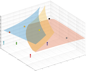
Based on the above constraints, the parametric phase diagram of the approximate solution can be drawn as in figure 7(a). It is worth noting that the parameter combinations in the white region of the phase diagram represent that the approximation conditions cannot be met, thus the approximate solutions cannot be obtained and only numerical solutions can be used. Furthermore, the same dimensionless group $(\varLambda {Re})^{4/3}{Re}[3\ln ({Ste}+1)/{Pe}]^{1/3}$ is found by generalizing all the constraints (5.11), (5.12), (5.22) and (5.23), in which parameters $\beta$ and $n$ can be considered as the other independent variables. This dimensionless group can be seen as the dimensionless form of product of characteristic time $\lambda$ and the wall shear rate ${\dot {\gamma }}_w|_{r=R}$ under different CCM conditions. Hence, it implies that we can use the dimensionless group $(\varLambda {Re})^{4/3}{Re}[3\ln ({Ste}+1)/{Pe}]^{1/3}$, $\beta$ and $n$ together to construct a three-dimensional parameter phase space to indicate the usable range of approximate solutions. It is noted that the dimensionless group is independent of the critical liquid film thickness due to the absence of $\beta$ and $n$ in the group, although the part $[3\varLambda Re\ln (Ste+1)/{Pe}]^{1/3}$ is shared.

Figure 7. (a) Analytical phase diagram of the approximate solutions. (b) Three-dimensional phase diagram of Q-Eq and N-Eq regions with $n$ and $\beta$ as independent variables for parameter space $0.1 \leqslant n \leqslant 0.9$ and $10^{-5} \leqslant \beta \leqslant 10^{-1}$.

Substituting $\bar {\delta }(\bar { H})$ from (5.7) and (5.20) into (2.47), we can finally obtain the approximate solutions of the Carreau model as follows.

For N-Eq region, we have

(5.26)\begin{align} \bar{ H} (\bar{t}) &= \left\{A^{{3n}/({3n+1})}- \frac{3n}{(3n+1)\bar{\rho}} \left[\frac{{Re}(\varLambda Re)^{1-n}}{A}\frac{(n+3)\mathcal{H}^n}{2(1-\beta)3^n}\right]^{{1}/({3n+1})}\right.\nonumber\\ &\quad \left.\times \left[\frac{\ln(Ste+1)}{Pe}\right]^{({2n+1})/({3n+1})} \bar{t} \right\}^{({3n+1})/{3n}}, \end{align}

and

(5.27) \begin{align} \bar{\delta}(\bar{t}) &= \left[\frac{A}{{Re}(\varLambda Re)^{1-n}}\frac{2(1-\beta)3^n}{(n+3)\mathcal{H}^n} \right]^{{1}/({3n+1})} \left[\frac{\ln({Ste}+1)}{Pe}\right]^{{n}/({3n+1})} \Biggl\{ A^{{3n}/({3n+1})}\nonumber\\ &\quad - \frac{3n}{(3n+1)\bar{\rho}} \left[\frac{{Re}(\varLambda Re)^{1-n}}{A}\frac{(n+3)\mathcal{H}^n}{2(1-\beta)3^n}\right]^{{1}/({3n+1})} \left[\frac{\ln(Ste+1)}{Pe}\right]^{({2n+1})/({3n+1})} \bar{t} \Biggr\}^{-{1}/{3n}} . \end{align}

It is noting that, with the limit of the power-law fluid from the Carreau fluid, i.e. $\beta = 0$ and $\varLambda Re \gg 1$ and recalling $\mathcal {H}(n)=1-\frac {1}{2} \sum _{j=1}^{\infty } \prod _{l=1}^j ({2 l-2 n})/({2 l+3})=3 n /(2 n+1)$, the (5.27) will be identical to (5.5).

For Q-Eq region, we have

(5.28) \begin{equation} \bar{ H} (\bar{t})= \Biggl\{ A^{{3}/{4}}- \frac{3}{4\bar{\rho}}\left(\frac{2{Re}}{3\beta A}\right)^{{1}/{4}} \left[\frac{\ln({Ste}+1)}{Pe}\right]^{{3}/{4}} \bar{t} \Biggr\}^{{4}/{3}} \end{equation}

and

(5.29) \begin{equation} \bar{\delta} (\bar{t})= \left[\frac{3\beta A}{2{Re}}\frac{\ln({Ste}+1)}{Pe}\right]^{{1}/{4}} \Biggl\{ A^{{3}/{4}}- \frac{3}{4\bar{\rho}}\left(\frac{2{Re}}{3\beta A}\right)^{{1}/{4}} \left[\frac{\ln({Ste}+1)}{Pe}\right]^{{3}/{4}} \bar{t} \Biggr\}^{-{1}/{3}}. \end{equation}

It is noted that, when $\beta = 1$ and $n = 1$ for Newtonian fluids, the approximate solutions for N-Eq region, i.e. (5.26) and (5.27), both disappear. In this case, (5.28) and (5.29) also reduce to the formulae for Newtonian fluids, which are identical to (5.4) and (5.5), respectively.

5.3. Discussion of approximate solutions

In order to determine the applicable range of the approximate solutions and to evaluate their degree of coincidence with numerical predictions, we transform the phase diagram in figure 7(a) into a three-dimensional phase diagram with $n$ and $\beta$ as two independent variables, as shown in figure 7(b). Above the blue surface is the control range of Q-Eq, while the space between the red and yellow surfaces is the control range of N-Eq. We estimated that the magnitude of the dimensionless group $3^{1/3}(\varLambda Re)^{4/3}Re (\ln (Ste+1))^{1/3}Pe^{-1/3}$ ranges from approximately $10^{-3}$ to $10^7$ based on the representative values of the following dimensional parameters $R = 0.01\unicode{x2013}1 \ \text {m}$, $\lambda = 1\unicode{x2013}5000 \ \text {s}$, $\mu _{0} = 0.1\unicode{x2013}1000 \ \text {Pa}\ \text {s}$ and dimensionless parameters ${Ste} = 0.05\unicode{x2013}1$, $A = 0.1\unicode{x2013}10$, ${Pe} = 10^4 \unicode{x2013}10^6$, $\varLambda Re = 10\unicode{x2013}10^5$, $Re = 10^{-2}\unicode{x2013}10^{2}$, while the range of values for $n$ and $\beta$ is consistent with the assumptions in the derivation process.

In figure 7(b), we also marked the positions for the four PCMs under all conditions in the phase diagram, which have been shown in figures 4 and 5. However, it can be found that these points are not located in the N-Eq and Q-Eq regions, meaning that none of these real cases satisfies the conditions for using an approximate solution. Therefore, we constructed six virtual cases (VC) to compare the difference between the approximate solution and the numerical prediction, and the relevant parameters of the cases are listed in table 2. Among them, three cases (VC1–3) are set to Q-Eq control, while the other three (VC4–5) belong to the N-Eq control space, and the points within the phase space of these cases are also plotted in figure 7.

Table 2. Dimensionless parameters for the virtual cases.

The comparison between the approximate solutions and numerical predictions are shown in figure 8(a) for VC1–3 and in figure 8(b) for VC4–5. In all the virtual cases, the approximate solutions and numerical predictions are found to be highly consistent, except for a small difference in the thickness of the liquid film near the end of melting. This confirms the validity of the proposed Q-Eq and N-Eq phase spaces. Accordingly, the use of approximate solutions rather than computationally expensive numerical solutions for cases that satisfy the phase space conditions can greatly reduce the cost for analysis.

Figure 8. (a) Comparison between the approximate solutions and numerical predictions of the dimensionless liquid film thickness $\bar {\delta }$ and remaining height $\bar { H}$ in virtual cases 1–3 controlled by Q-Eq. (b) Comparison between the approximate solutions and numerical predictions of the dimensionless liquid film thickness $\bar {\delta }$ and remaining height $\bar {H}$ of virtual cases 4–6 controlled by N-Eq and comparison with the power-law approximation solutions.

In addition, it is interesting to note that VC5 changes the $\beta$ value from $10^{-2}$ to $10^{-5}$ compared with VC4, but the melting processes of the two cases are identical. This means that, in the case of the current dimensionless group $3^{1/3}(\varLambda Re)^{4/3}{Re} (\ln (Ste+1))^{1/3}Pe^{-1/3}$, the shear rates everywhere in the liquid film are in the low shear rate range of the power-law region, and changing the $\beta$ value does not affect the CCM process, as shown in figure 2. Moreover, as previously demonstrated in § 4.3, when the CCM process is completely controlled by N-Eq, the Carreau model and the power-law model are essentially equivalent. Therefore, as shown in figure 8(b), we can find that the two approximate solutions in the phase space N-Eq control space are also equivalent for cases VC4–6.

6. Concluding remarks

In this work, we established a theoretical framework to model the CCM of shear-thinning fluids based on the Carreau and power-law models. We found excellent agreement between the melt film thickness and remaining height predicted by our numerical solutions of the Carreau model and those obtained from experimental results in all cases. Furthermore, we showed that convection within the liquid film deteriorates the heat transfer and lowers the melting rate because the velocity $\bar {u}_{z}$ is in the opposite direction to the temperature gradient. Our theoretical framework revealed the existence of critical liquid film thickness for Carreau fluids, i.e. $\delta _{cr}=\{ 3R\lambda k_{l} \ln ({Ste}+1) /[\rho _{l}c_{{p,l}}(1/\beta -1)^{1/(1-n)} ] \}^{1/3}$ . Three scenarios of CCM may occur, namely $\mathcal {PQ}$ control, $\mathcal {MN}$ control and $\mathcal {PQ}-\mathcal {MN}$ transition, depending on whether the liquid film thickness is always smaller ($\delta _{end} < \delta _{cr}$), always greater ($\delta _{t=0} > \delta _{cr}$) or crossing ($\delta _{t=0} < \delta _{athrm{cr}} < \delta _{end}$) the critical liquid film thickness, respectively. Numerical prediction results demonstrated that the CCM process of $\mathcal {MN}$-controlled Carreau fluids is almost equivalent to that of power-law fluids.

Finally, approximate analytical models were developed for gaining fundamental understanding of the problem, which provides fast estimation for both the Carreau and power-law cases. We also identified a key dimensionless group $(\varLambda Re)^{4/3}{Re} (3\ln (Ste+1))^{1/3}Pe^{-1/3}$ to construct a three-dimensional parameter phase space to indicate the usable range of approximate solutions. We revealed that two approximate solution spaces (Q-Eq and N-Eq) are distributed in the phase space and verified the reliability of the approximate solutions by comparing them with the numerical solutions. It is noted that the approximate solution of the power-law model is almost equivalent to the Carreau model in the N-Eq region. These approximate solutions enable convenient and low-cost computation to predict the dynamic process of CCM for shear-thinning fluids. In addition to the rheological effect studied in this work, other complexities, such as non-uniform melt film layer thickness, sensible heating effect and temperature-dependent thermophysical properties of the PCM, will be of interest for further extending the CCM model toward more realistic situations.

Acknowledgements

We thank Dr X.-F. Shao at Southwest Jiaotong University for providing original rheological data of sugar alcohols. N.H. especially thanks his wife M.-L. Ye for her encouragement and support.

Funding

This work was supported by the National Natural Science Foundation of China under grant no. 52276088. L.-W.F. would like to thank a start-up fund granted by the ‘100 Talents Program’ of Zhejiang University. N.H. would like to thank a fund granted by the ‘Strive for Excellent Doctoral Dissertation’ of Zhejiang University.

Declaration of interests

The authors report no conflict of interest.

Author contributions

N.H. derived the theory, performed the simulations and conducted the experiments. L.-W.F. conceived the idea, revised the derivation and supervised the work.

Appendix A. Derivation of relationship between $\bar {Q}$ and ${\bar {\dot {\gamma }}}_{w}$

Differentiating both sides of (2.21) yields

(A1) \begin{align} \mathrm{d}\bar{\tau}&=\frac{1}{Re}[ \beta+(1-\beta)(1+\varLambda^{2}{Re}^{2}\bar{\dot{\gamma}}^2)^{({n-1})/{2}}\nonumber\\ &\quad +(1-\beta)(n-1) \bar{\dot{\gamma}}\varLambda^{2}{Re}^{2}(1+\varLambda^{2}{Re}^{2}\bar{\dot{\gamma}}^2)^{({n-3})/{2}}]\mathrm{d}\bar{\dot{\gamma}}, \end{align}

and then substituting this equation into (2.22) leads to

(A2) \begin{align} \frac{\bar{Q}}{{\bar{\delta}}^{2}{\rm \pi} \bar{r}} &=\frac{1}{{\bar{\tau}}_{w}^{2}{Re}^{2}}\int\limits_{0}^{\bar{\dot{\gamma}}_{w}} \{ \bar{\dot{\gamma}}^2 [\beta+(1-\beta)(1+\varLambda^{2}{Re}^{2}\bar{\dot{\gamma}}^2)^{({n-1})/{2}}] \nonumber\\ &\quad \times [\beta+(1-\beta)(1+\varLambda^{2}{Re}^{2}\bar{\dot{\gamma}}^2)^{({n-1})/{2}}\nonumber\\ &\quad +(1-\beta)(n-1)\bar{\dot{\gamma}}\varLambda^{2}{Re}^{2}(1+ \varLambda^{2}{Re}^{2}\bar{\dot{\gamma}}^2)^{({n-3})/{2}}]\} \mathrm{d}\dot{\gamma}\nonumber\\ &=\frac{1}{{\bar{\tau}}_{w}^{2}{Re}^{2}}\int\limits_{0}^{\bar{\dot{\gamma}}_{w}} [ \beta^{2}\bar{\dot{\gamma}}^2 + 2\beta(1-\beta)\bar{\dot{\gamma}}^2(1+\varLambda^{2}{Re}^{2}\bar{\dot{\gamma}}^2)^{({n-1})/{2}}\nonumber\\ &\quad + (1-\beta)^2\bar{\dot{\gamma}}^2(1+\varLambda^{2}{Re}^{2}\bar{\dot{\gamma}}^2)^{n-1} \nonumber\\ &\quad +\beta(1-\beta)(n-1) \varLambda^{2}{Re}^{2}\bar{\dot{\gamma}}^4(1+ \varLambda^{2}{Re}^{2}\bar{\dot{\gamma}}^2)^{({n-3})/{2}}\nonumber\\ &\quad +(1-\beta)^{2}(n-1) \varLambda^{2}{Re}^{2}\bar{\dot{\gamma}}^4(1+\varLambda^{2}{Re}^{2}\bar{\dot{\gamma}}^2)^{n-2}] \mathrm{d}\bar{\dot{\gamma}}\nonumber\\ &= \frac{1}{{\bar{\tau}}_{w}^{2}{Re}^{2}} \left\{ \frac{1}{3} \beta^2 \bar{\dot{\gamma}}_{w}^3 + \frac{1}{3}\bar{\dot{\gamma}}_{w}^{3} 2\beta(1-\beta)(1+ \varLambda^{2}{Re}^{2}\bar{\dot{\gamma}}_{w}^{2})^{({n-1})/{2}} \right.\nonumber\\ &\quad + \frac{1}{3}\bar{\dot{\gamma}}_{w}^{3}(1-\beta)^2 (1+\varLambda^{2}{Re}^{2}\bar{\dot{\gamma}}_{w}^{2})^{n-1} \nonumber\\ & \quad + \frac{n-1}{3} \int\limits_{0}^{\bar{\dot{\gamma}}_{w}} [ \beta(1-\beta)\varLambda^{2} {Re}^{2}\bar{\dot{\gamma}}^4 (1+\varLambda^{2}{Re}^{2}\bar{\dot{\gamma}}^{2})^{({n-3})/{2}}\nonumber\\ &\quad \left.\vphantom{\frac{1}{3} } + (1-\beta)^2 \varLambda^{2}{Re}^{2}\bar{\dot{\gamma}}^4 (1+\varLambda^{2}{Re}^{2}\bar{\dot{\gamma}}^{2})^{n-2}] \mathrm{d}\bar{\dot{\gamma}} \right\} , \end{align}

where

(A3) \begin{equation} \bar{\tau}_{w} = \frac{1}{Re} [ \beta+(1-\beta)(1+\varLambda^{2} {Re}^{2} \bar{\dot{\gamma}}_{w}^{2})^{({n-1})/{2}} ]\bar{\dot{\gamma}}_{w} . \end{equation}

After simplification, it can be written in the form of hypergeometric functions ${}_{2}F_{1}(a,b;c;z)$ as

(A4) \begin{align} \frac{\bar{Q}}{{\bar{\delta}}^{2}{\rm \pi} \bar{r}} &= \frac{1}{3}\bar{\dot{\gamma}}_{w} -\frac{n-1}{3{\bar{\tau}}_{w}^{2}{Re}^{2}} \Biggl[ {}_{2}F_{1}\left(\frac{5}{2},\frac{3-n}{2};\frac{7}{2};-\varLambda^{2}{Re}^{2}\bar{\dot{\gamma}}^2\right) \frac{\beta(1-\beta)\varLambda^{2}{Re}^{2}\bar{\dot{\gamma}}^5}{5} \nonumber\\ &\quad + {}_{2}F_{1}\left(\frac{5}{2},2-n;\frac{7}{2};-\varLambda^{2}{Re}^{2}\bar{\dot{\gamma}}^2\right) \frac{\left(1-\beta \right )^{2} \varLambda^{2}{Re}^{2}\bar{\dot{\gamma}}^5}{5}\Biggr]. \end{align}

Following the partial integration method for (A2), we can finally get a convergent series as

(A5) \begin{align} \frac{\bar{Q}}{{\bar{\delta}}^{2}{\rm \pi} \bar{r}}&= \frac{1}{3}\bar{\dot{\gamma}}_{w} \left\{ 1 - \frac{\sum_{j=1}^{\infty }\beta(1-\beta) ({Re}\varLambda \bar{\dot{\gamma}}_{w})^{2j}(1+\varLambda^{2} {Re}^{2} \bar{\dot{\gamma}}_{w}^{2})^{({n-1-2j})/{2}} \prod_{l=1}^{j}\dfrac{2l-n-1}{2l+3}} {[\beta+(1-\beta)(1+\varLambda^{2} {Re}^{2} \bar{\dot{\gamma}}_{w}^{2})^{({n-1})/{2}}]^2} \right. \nonumber\\ &\quad \left. - \frac{\sum_{j=1}^{\infty }\frac{1}{2}(1-\beta)^{2}({Re}\varLambda \bar{\dot{\gamma}}_{w})^{2j}(1+\varLambda^{2} {Re}^{2} \bar{\dot{\gamma}}_{w}^{2})^{n-1-j} \prod_{l=1}^{j}\dfrac{2l-2n}{2l+3}} {[\beta+(1-\beta)(1+\varLambda^{2} {Re}^{2} \bar{\dot{\gamma}}_{w}^{2})^{({n-1})/{2}}]^2} \right \}, \end{align}

which can be rearranged into

(A6) \begin{align} \frac{\bar{Q}}{{\bar{\delta}}^{2}{\rm \pi} \bar{r}} &= \frac{1}{3}\bar{\dot{\gamma}}_{w} \left\{\vphantom{\prod_{l=1}^{j}}1 - \frac{\beta(1-\beta)(1+\varLambda^{2} {Re}^{2} \bar{\dot{\gamma}}_{w}^{2})^{({n-1})/{2}}}{[\beta+(1-\beta)(1+\varLambda^{2} {Re}^{2} \bar{\dot{\gamma}}_{w}^{2})^{({n-1})/{2}}]^2}\right.\nonumber\\ &\left.\quad \times \sum_{j=1}^{\infty}\frac{(\varLambda^{2} {Re}^{2}\bar{\dot{\gamma}}_{w}^{2})^{j}}{(1+\varLambda^{2}{Re}^{2} \bar{\dot{\gamma}}_{w}^{2})^{j}} \prod_{l=1}^{j}\frac{2l-n-1}{2l+3} \right.\nonumber\\ &\left.\quad -\, \frac{\frac{1}{2}(1-\beta)^{2}(1+\varLambda^{2} {Re}^{2} \bar{\dot{\gamma}}_{w}^{2})^{n-1}}{[\beta+(1-\beta)(1+\varLambda^{2} {Re}^{2} \bar{\dot{\gamma}}_{w}^{2})^{({n-1})/{2}}]^2} \sum_{j=1}^{\infty}\frac{(\varLambda^{2} {Re}^{2}\bar{\dot{\gamma}}_{w}^{2})^{j}}{(1+\varLambda^{2}{Re}^{2} \bar{\dot{\gamma}}_{w}^{2})^{j}} \prod_{l=1}^{j}\frac{2l-2n}{2l+3} \right\}. \end{align}

The results of $\bar {Q}/(\delta ^{2}{\rm \pi} \bar {r})$ with ${\bar {\dot {\gamma }}}_{w}$ under various $n$ and number of terms $j$ are depicted in figure 9 by numerically computing the series in (A6), which implies that $\bar {Q}/(\delta ^{2}{\rm \pi} \bar {r})$ can be calculated by finite series.

Appendix B. Derivation of force balance equation based on the Carreau model

Integrating (2.29) with $\bar {r}$ leads to the expression of pressure distribution $\bar {P}(\bar {r})$, as given by

(B1)\begin{align} \bar{P} = \begin{cases} -\dfrac{1}{Re}\dfrac{3V^{{\ast}}}{{\bar{\delta}}^3}{\bar{r}}^2 +C_1 & \text{if } \bar{r}\ll \dfrac{{\bar{\delta}}^2}{3V^{{\ast}} \varLambda Re}, \\ -\dfrac{2(1-\beta)}{{Re}\left(\varLambda Re\right)^{1-n}}\left(\dfrac{3V^{{\ast}}}{ \mathcal{H}(n)}\right)^{n} \dfrac{1}{{\bar{\delta}}^{2n+1}}\dfrac{{\bar{r}}^{n+1}}{n+1}+C_2 & \text{if } \dfrac{{\bar{\delta}}^2\mathcal{H}(n)}{3V^{{\ast}} \varLambda Re} \ll \bar{r} \\ & {} \quad\ll \dfrac{{\bar{\delta}}^2\mathcal{H}(n)}{3V^{{\ast}} \varLambda Re} \left(\dfrac{1-\beta}{\beta}\right)^{{1}/({1-n}) }, \\ -\dfrac{\beta}{Re}\dfrac{3V^{{\ast}}}{{\bar{\delta}}^3}{\bar{r}}^2 +C_3 & \text{if } \bar{r}\gg \dfrac{{\bar{\delta}}^2}{3V^{{\ast}} \varLambda Re} \left(\dfrac{1-\beta}{\beta}\right)^{{1}/({1-n})}, \end{cases} \end{align}

where $C_1$, $C_2$ and $C_3$ are integral constants and can be determined by boundary conditions of $\mathrm {d} \bar {P}/\mathrm {d} \bar {r}|_{\bar {r}=0}=0$ and zero gauge pressure $\bar {P}(\bar {r} =1) = 0$ as well as continuity at the interface. In order to obtain an explicit pressure distribution function, here, we treated the region near the two characteristic dividing points of the above equation as an asymptotic approximation.

Figure 9. Variations of ${\bar {Q}}/{\delta ^{2}{\rm \pi} \bar {r}}$ with ${\bar {\gamma }}_{w}$ for $\varLambda Re = 10$ as a representative case (yellow lines, comparison of series for various number of terms $j$; red lines, $\beta = 10^{-4}$; and blue lines, $\beta = 10^{-3}$).

Hence, if

(B2a,b)\begin{equation} \frac{{\bar{\delta}}^2}{3V^{{\ast}} \varLambda {Re}} \leqslant 1\quad {\rm and} \quad \frac{{\bar{\delta}}^2}{3V^{{\ast}} \varLambda {Re}} \left(\frac{1-\beta}{\beta}\right)^{{1}/({1-n})} > 1, \end{equation}

the asymptotic form of (B1) can be written as

(B3)\begin{equation} \bar{P} = \begin{cases} -\dfrac{1}{Re}\dfrac{3V^{{\ast}}}{{\bar{\delta}}^3}{\bar{r}}^2 +A_1 & \text{if } 0\leqslant \bar{r} \leqslant \dfrac{{\bar{\delta}}^2}{3V^{{\ast}} \varLambda {Re}}, \\ -\dfrac{2(1-\beta)}{{Re}\left(\varLambda {Re}\right)^{1-n}}\left(\dfrac{3V^{{\ast}}}{ \mathcal{H}(n)}\right)^{n}\dfrac{1}{{\bar{\delta}}^{2n+1}} \dfrac{{\bar{r}}^{n+1}-1}{n+1} & \text{if } \dfrac{{\bar{\delta}}^2}{3V^{{\ast}} \varLambda Re} \leqslant \bar{r} \leqslant 1, \end{cases} \end{equation}

where

(B4)\begin{align} A_1 = \frac{1}{Re} \frac{1}{(\varLambda {Re})^2} \frac{\bar{\delta}}{ 3V^{{\ast}}} \left[1-\frac{2(1-\beta)}{(n+1)(\mathcal{H}(n))^n}\right] +\frac{2(1-\beta)}{{Re}(\varLambda Re)^{1-n}}\left(\frac{3V^{{\ast}}}{ \mathcal{H}(n)}\right)^{n} \frac{1}{{\bar{\delta}}^{2n+1}}\frac{1}{n+1}. \end{align}

Substituting (B3) into (2.12) and integrating with $\bar {r}$ from $0$ to $1$ lead to

(B5)\begin{equation} \mathcal{M}\frac{{\bar{\delta}}^5}{\left(V^{{\ast}}\right)^3} + \mathcal{N} \frac{\left(V^{{\ast}}\right)^n}{{\bar{\delta}}^{2n+1}}= \bar{ H} -\bar{\delta}, \end{equation}

where

(B6)\begin{equation} \mathcal{M} = \frac{A}{27Re}\frac{1}{(\varLambda {Re})^4} \left[\frac{1}{2}-\frac{2(1-\beta)}{(n+3)(\mathcal{H}(n))^n} \right], \end{equation}

and

(B7)\begin{equation} \mathcal{N} = \frac{A}{Re}\frac{1-\beta}{(\varLambda {Re})^{1-n}} \frac{2}{n+3}\left(\frac{3}{\mathcal{H}(n)}\right)^n. \end{equation}

If

(B8)\begin{equation} \frac{{\bar{\delta}}^2}{3V^{{\ast}} \varLambda {Re}} \left(\frac{1-\beta}{\beta}\right)^{{1}/({1-n})} \leqslant 1, \end{equation}

the asymptotic form of (B1) can be written as

(B9)\begin{equation} \bar{P} = \begin{cases} -\dfrac{1}{Re}\dfrac{3V^{{\ast}}}{{\bar{\delta}}^3}{\bar{r}}^2 +B_1 & \text{if } 0\leqslant \bar{r} \leqslant \dfrac{{\bar{\delta}}^2}{3~V^{{\ast}} \varLambda \mathit{Re}}, \\ -\dfrac{2(1-\beta)}{{Re}\left(\varLambda Re\right)^{1-n}}\left(\frac{3V^{{\ast}}}{\mathcal{H}(n)}\right)^{n} \dfrac{1}{{\bar{\delta}}^{2n+1}}\dfrac{{\bar{r}}^{n+1}}{n+1}+B_2 & \text{if } \dfrac{{\bar{\delta}}^2}{3V^{{\ast}} \varLambda Re} \leqslant \bar{r} \\ & {} \quad \leqslant \dfrac{{\bar{\delta}}^2}{3V^{{\ast}} \varLambda Re}\left(\dfrac{1-\beta}{\beta}\right)^{{1}/({1-n})}, \\ -\dfrac{\beta}{Re}\dfrac{3V^{{\ast}}}{{\bar{\delta}}^3}({\bar{r}}^2 -1) & \text{if } \dfrac{{\bar{\delta}}^2}{3V^{{\ast}} \varLambda Re}\left(\dfrac{1-\beta}{\beta}\right)^{{1}/({1-n})}\\ & {} \quad \leqslant \bar{r} \leqslant 1, \end{cases} \end{equation}

where

(B10) \begin{align} B_2 &= \frac{1}{Re} \frac{1}{(\varLambda {Re})^2} \frac{\bar{\delta}}{ 3V^{{\ast}}} \Biggl[-\beta\left(\frac{1-\beta}{\beta}\right)^{{2}/({1-n})}+ \frac{2(1-\beta)}{(n+1)(\mathcal{H}(n))^n}\left(\frac{1-\beta}{\beta}\right)^{({1+n})/({1-n})}\Biggr]\nonumber\\ &\quad + \frac{\beta}{Re}\frac{3V^{{\ast}}}{{\bar{\delta}}^3}, \end{align}

and

(B11)\begin{equation} B_1 = \frac{1}{Re}\frac{1}{(\varLambda {Re})^2}\frac{\bar{\delta}}{3V^{{\ast}}} \left[1-\frac{2(1-\beta)}{(n+1)(\mathcal{H}(n))^n}\right]+B_2. \end{equation}

Similarly, substituting (B9) into (2.12) and integrating with $\bar {r}$ from $0$ to $1$ leads to

(B12)\begin{equation} \mathcal{P}\frac{{\bar{\delta}}^5}{\left(V^{{\ast}}\right)^3} + \mathcal{Q} \frac{V^{{\ast}}}{{\bar{\delta}}^{3}} = \bar{H} -\bar{\delta}, \end{equation}

where

(B13) \begin{align} \mathcal{P} &= \frac{A}{27Re}\frac{1}{(\varLambda {Re})^4} \Biggl[ \frac{1}{2}+\frac{-2}{n+3}\frac{(1- \beta)}{(\mathcal{H}(n))^n} +\frac{2}{n+3}\frac{1-\beta}{(\mathcal{H}(n))^n}\left(\frac{1-\beta}{\beta}\right)^{({3+n})/({1-n})}\nonumber\\ &\quad +\frac{-\beta}{2}\left(\frac{1-\beta}{\beta}\right)^{{4}/({1-n})} \Biggr], \end{align}

and $\mathcal {Q}=({3\beta }/{2})({A}/{Re})$.

Appendix C. Valuation of ${\bar {u}}_z$ in energy equation considering the convective effect

First, for Newtonian or power-law fluids, we can obtain explicit expressions for the velocity distribution ${\bar {u}}_r$ by substituting the pressure gradient from (2.16) into (2.15), as given by

(C1) \begin{equation} \bar{u}_{r}(\bar{r}, \bar{z}, \bar{t})=\frac{2 n+1}{n+1} \frac{2^{1 / n} V^*}{\bar{\delta}^{2+1 / n}} \bar{r}\Biggl[\left(\frac{\bar{\delta}}{2}\right)^{1+1 / n}-\left|\frac{\bar{\delta}}{2}-\bar{z}\right|^{1+1 / n}\Biggr], \end{equation}

where $n=1$ represents to Newtonian fluids. Substituting (C1) into the continuity equation and integrating along the z direction leads to

(C2) \begin{align} \bar{u}_{z}(\bar{z}, \bar{t}) & ={-}\int_0^{\bar{z}} \frac{1}{\bar{r}} \frac{\partial}{\partial \bar{r}}\left(\bar{r} u_{\mathrm{r}}\right) \mathrm{d} \bar{z}\nonumber\\ &=V^*\Biggl\{\frac{n}{2 n+2}\left(2 \frac{\bar{z}}{\bar{\delta}}-1\right)\left[\left(2 \frac{\bar{z}}{\bar{\delta}}-1 \right) {\cdot} \operatorname{sign}\left(2 \frac{\bar{z}}{\bar{\delta}}-1\right)\right]^{1+1 / n}\nonumber\\ &\quad -\frac{2 n+1}{n+1} \frac{\bar{z}}{\bar{\delta}}+\frac{n}{2 n+2}\Biggr\}. \end{align}

Especially, when $n = 1$ for Newtonian fluids, the distribution of dimensionless ${\bar {u}}_z$ becomes

(C3) \begin{equation} \bar{u}_z(\bar{z}, \bar{t})=V^*\Biggl[2\left(\frac{\bar{z}}{\bar{\delta}}\right)^3-3\left(\frac{\bar{z}}{\bar{\delta}}\right)^2\Biggr]. \end{equation}

It can also be derived from (C2) that the dimensionless ${\bar {u}}_z$ for ${n} \rightarrow 0$ is

(C4)\begin{equation} \bar{u}_z(\bar{z}, \bar{t})={-}\frac{\bar{z}}{\bar{\delta}} V^*. \end{equation}

The plot of (C2) for various $n$ is presented in figure 10(a), which indicates that (C3) and (C4) are the limit of possible cases of velocity distribution for power-law fluids. By substituting (C2) into (2.10), one can obtain

(C5a,b)\begin{equation} f\left(\frac{\bar{z}}{\bar{\delta}}\right) V^* \frac{\partial \bar{T}}{\partial \bar{z}}= \frac{\partial^2 \bar{T}}{\partial \bar{z}^2},\quad f\left(\frac{\bar{z}}{\bar{\delta}}\right)=\left\{\begin{array}{ll} 0, & \text{for conduction,} \\ -1, & \text{for uniform distribution,} \\ -\bar{z} / \bar{\delta}, & \text{for $ n=0$,} \\ 2 \bar{z}^3 / \bar{\delta}^3-3 \bar{z}^2 / \bar{\delta}^2, & \text{for $n=1$.} \end{array}\right. \end{equation}

where no explicit temperature profile can be obtained for $n=0$ and $n=1$.

Figure 10. (a) Dimensionless velocity ${\bar {u}}_z$ of power-law fluids for different $n$. (bd) Comparison of different assumptions: (b) dimensionless temperature profile $\bar {T}(\bar {z})$ and (c) temperature gradient distribution $\mathrm {d}\bar T/\mathrm {d}\bar {z}$ by taking ${Pe}V^{\ast }=1$ as an example. (d) Temperature gradient $\mathrm {d}\bar {T}/\mathrm {d}\bar {z}$ at $\bar {z} = \bar {\delta }$ for different ${Pe}V^{\ast }$.

Hence, numerical solutions were sought for both cases for temperature comparison, as shown in figure 10(b). By taking ${Pe}V^{\ast } = 1$ as an example, it indicates that uniform ${\bar {u}}_z = -V^{\ast }$ will enlarge the convection effect, and that the non-Newtonian parameter n seems to have little impact on the temperature profile. This demonstrates that non-Newtonian effects have minimal impact on the distribution of temperature. When focusing on the temperature gradient at the phase interface $\bar {z} = \bar {\delta }$, a certain difference can be found with ${Pe}V^{\ast } = 1$, as shown in figure 10(c). By going through a wide range of ${Pe}V^{\ast }$, the results are shown in figure 10(d), demonstrating that using uniform velocity distribution will cause a slightly underestimated heat flux through the solid–liquid interface. However, although it is not valid at $z = 0$, the simplification of ${\bar {u}}_z = -V^{\ast }$ can reflect the trend of convection effect under different ${Pe}V^{\ast }$, thus providing an explicit and simple temperature expression for the CCM model. Regarding Carreau fluids, due to their complex constitutive expressions, an explicit velocity distribution ${\bar {u}}_{r}$ cannot be obtained and inputted into the continuity equation to derive a velocity distribution ${\bar {u}}_{z}$. However, given that the Carreau model can be approximately treated as a combination of the Newtonian region and power-law region, it can be considered that the above proof is also valid for a Carreau fluid. Another justification is that the model predictions obtained by this simplification were also in good agreement with our experimental data (with ${Ste}$ from 0.104 to 0.412).

References

Agbessi, Y., Alibenyahia, B., Nouar, C., Lemaitre, C. & Choplin, L. 2015 Linear stability of Taylor–Couette flow of shear-thinning fluids: modal and non-modal approaches. J. Fluid Mech. 776, 354389.CrossRefGoogle Scholar
Allouche, M.H., Botton, V., Millet, S., Henry, D., Dagois-Bohy, S., Guzel, B. & Ben Hadid, H. 2017 Primary instability of a shear-thinning film flow down an incline: experimental study. J. Fluid Mech. 821, R1.CrossRefGoogle Scholar
Bejan, A. 1992 Single correlation for theoretical contact melting results in various geometries. Intl Commun. Heat Mass Transfer 19 (4), 473483.CrossRefGoogle Scholar
Boyko, E. & Stone, H.A. 2021 Flow rate-pressure drop relation for shear-thinning fluids in narrow channels: approximate solutions and comparison with experiments. J. Fluid Mech. 923, 621.CrossRefGoogle Scholar
Chekila, A., Nouar, C., Plaut, E. & Nemdili, A. 2011 Subcritical bifurcation of shear-thinning plane poiseuille flows. J. Fluid Mech. 686, 272298.CrossRefGoogle Scholar
Chen, W.Z., Hao, J.L. & Chen, Z.Y. 2013 A study of self-burial of a radioactive waste container by deep rock melting. Sci. Technol. Nucl. Ins. 2013, 184757.Google Scholar
Chen, Z.H., Hu, X.C., Hu, K., Utaka, Y. & Mori, S. 2020 Measurement of the microlayer characteristics in the whole range of nucleate boiling for water by laser interferometry. Intl J. Heat Mass Transfer 146, 118856.CrossRefGoogle Scholar
Dong, Z.F., Chen, Z.Q., Wang, Q.J. & Ebadian, M.A. 1991 Experimental and analytical study of contact melting in a rectangular cavity. J. Therm. Heat Transfer 5 (3), 347354.CrossRefGoogle Scholar
Emerman, S.H. & Turcotte, D.L. 1983 Stokes's problem with melting. Intl J. Heat Mass Transfer 26 (11), 16251630.CrossRefGoogle Scholar
Esfahani, B.R., Hirata, S.C., Berti, S. & Calzavarini, E. 2018 Basal melting driven by turbulent thermal convection. Phys. Rev. Fluids 3 (5), 053501.CrossRefGoogle Scholar
Fomin, S.A., Saitoh, T.S. & Chugunov, V.A. 1997 Contact melting materials with non-linear properties. Heat Mass Transfer 33 (3), 185192.CrossRefGoogle Scholar
Fomin, S.A., Wei, P.S. & Chugunov, V.A. 1995 Contact melting by a nonisothermal heating surface of arbitrary shape. Intl J. Heat Mass Transfer 38 (17), 32753284.CrossRefGoogle Scholar
Fu, W.C., Yan, X., Gurumukhi, Y., Garimella, V.S., King, W.P. & Miljkovic, N. 2022 High power and energy density dynamic phase change materials using pressure-enhanced close contact melting. Nat. Energy 7, 270280.CrossRefGoogle Scholar
Groulx, D. & Lacroix, M. 2007 Study of the effect of convection on close contact melting of high Prandtl number substances. Intl J. Therm. Sci. 46 (3), 213220.CrossRefGoogle Scholar
Guo, Z.Y., Tao, W.Q. & Shah, R. 2005 The field synergy (coordination) principle and its applications in enhancing single phase convective heat transfer. Intl J. Heat Mass Transfer 48 (9), 17971807.CrossRefGoogle Scholar
Henot, M., Plihon, N. & Taberlet, N. 2021 Onset of glacier tables. Phys. Rev. Lett. 127 (10), 108501.CrossRefGoogle ScholarPubMed
Hu, N., Li, Z.R., Xu, Z.W. & Fan, L.W. 2022 Rapid charging for latent heat thermal energy storage: a state-of-the-art review of close-contact melting. Renew. Sust. Energy Rev. 155, 111918.CrossRefGoogle Scholar
Hu, N., Zhang, R.H., Zhang, S.T., Liu, J. & Fan, L.W. 2019 A laser interferometric measurement on the melt film thickness during close-contact melting on an isothermally-heated horizontal plate. Intl J. Heat Mass Transfer 138, 713718.CrossRefGoogle Scholar
Hu, N., Zhu, Z.Q., Li, Z.R., Tu, J. & Fan, L.W. 2018 Close-contact melting heat transfer on a heated horizontal plate: revisited in the presence of nano-enhanced phase change materials (NePCM). Intl J. Heat Mass Transfer 124, 794799.CrossRefGoogle Scholar
Kozak, Y. 2022 Theoretical analysis of close-contact melting on superhydrophobic surfaces. J. Fluid Mech. 943, A39.CrossRefGoogle Scholar
Kozak, Y., Rozenfeld, T. & Ziskind, G. 2014 Close-contact melting in vertical annular enclosures with a non-isothermal base: theoretical modeling and application to thermal storage. Intl J. Heat Mass Transfer 72, 114127.CrossRefGoogle Scholar
Kozak, Y., Zeng, Y., Al Ghossein, R.M., Khodadadi, J.M. & Ziskind, G. 2019 Close-contact melting on an isothermal surface with the inclusion of non-Newtonian effects. J. Fluid Mech. 865, 720742.CrossRefGoogle Scholar
Kumar, P., Zuri, S., Kogan, D., Gottlieb, M. & Sayag, R. 2021 Lubricated gravity currents of power-law fluids. J. Fluid Mech. 916, A33.CrossRefGoogle Scholar
Marsh, B.D. 1978 On the cooling of ascending andesitic magma. Phil. Trans. R. Soc. Lond. A 288 (1355), 611625.Google Scholar
Mayer, P. & Moaveni, S. 2008 Close-contact melting as a subtractive machining process. Intl J. Advan. Manuf. Tech. 37 (9–10), 980995.CrossRefGoogle Scholar
Moallemi, M.K. & Viskanta, R. 1985 Experiments on fluid-flow induced by melting around a migrating heat-source. J. Fluid Mech. 157, 3551.CrossRefGoogle Scholar
Moallemi, M.K., Webb, B.W. & Viskanta, R. 1986 An experimental and analytical study of close-contact melting. Trans. ASME J. Heat Transfer 108 (4), 894899.CrossRefGoogle Scholar
Moore, F.E. & Bayazitoglu, Y. 1982 Melting within a spherical enclosure. Trans. ASME J. Heat Transfer 104 (1), 1923.CrossRefGoogle Scholar
Motahar, S., Nikkam, N., Alemrajabi, A.A., Khodabandeh, R., Toprak, M.S. & Muhammed, M. 2014 A novel phase change material containing mesoporous silica nanoparticles for thermal storage: a study on thermal conductivity and viscosity. Intl Commun. Heat Mass Transfer 56, 114120.CrossRefGoogle Scholar
Nouar, C., Bottaro, A. & Brancher, J.P. 2007 Delaying transition to turbulence in channel flow: revisiting the stability of shear-thinning fluids. J. Fluid Mech. 592, 177194.CrossRefGoogle Scholar
Saito, A., Utaka, Y., Akiyoshi, M. & Katayama, K. 1985 a On the contact heat-transfer with melting. 1. Experimental-study. Bull. JSME 28 (240), 11421149.CrossRefGoogle Scholar
Saito, A., Utaka, Y., Akiyoshi, M. & Katayama, K. 1985 b On the contact heat-transfer with melting. 2. Analytical study. Bull. JSME 28 (242), 17031709.CrossRefGoogle Scholar
Schueller, K. & Kowalski, J. 2017 Spatially varying heat flux driven close-contact melting – a Lagrangian approach. Intl J. Heat Mass Transfer 115, 12761287.CrossRefGoogle Scholar
Schuller, K., Kowalski, J. & Raback, P. 2016 Curvilinear melting – a preliminary experimental and numerical study. Intl J. Heat Mass Transfer 92, 884892.CrossRefGoogle Scholar
Shao, X.F., Chen, C.L., Yang, Y.J., Ku, X.K. & Fan, L.W. 2019 Rheological behaviors of sugar alcohols for low-to-medium temperature latent heat storage: effects of temperature in both the molten and supercooled liquid states. Sol. Energy Mater Sol. Cells 195, 142154.CrossRefGoogle Scholar
Shao, X.F., Yang, S., Chen, C.L., Fan, L.W. & Yu, Z.T. 2021 Temperature-dependent rheological behaviors of binary eutectic mixtures of sugar alcohols for latent heat storage: a comparative study with pure sugar alcohols. J. Therm. Sci. 30 (6), 20022014.CrossRefGoogle Scholar
Sinha, G.K., Narayan, S. & Srivastava, A. 2021 Microlayer dynamics during the growth process of a single vapour bubble under subcooled flow boiling conditions. J. Fluid Mech. 931, A23.CrossRefGoogle Scholar
Sochi, T. 2015 Analytical solutions for the flow of Carreau and Cross fluids in circular pipes and thin slits. Rheol. Acta 54 (8), 745756.CrossRefGoogle Scholar
Sparrow, E.M. & Geiger, G.T. 1986 Melting in a horizontal tube with the solid either constrained or free to fall under gravity. Intl J. Heat Mass Transfer 29 (7), 10071019.CrossRefGoogle Scholar
Wilkinson, W.L. 1972 Non-Newtonian flow and heat transfer. P. I. Mech. Engng 186 (1), 109116.Google Scholar
Yoo, H., Hong, H. & Kim, C.J. 1998 Effects of transverse convection and solid-liquid density difference on the steady close-contact melting. Intl J. Heat Fluid Flow 19 (4), 368373.CrossRefGoogle Scholar
Figure 0

Figure 1. Schematic illustration of the flow and heat transfer in the axisymmetric CCM region having radius $R$ and thickness $\delta$, where $R \gg \delta$ and $H(0)/R$ is arbitrary.

Figure 1

Figure 2. Theoretical prediction of viscosity for (a) Carreau model and (b) power-law model, where the dashed line represents the baseline at $\mu _{0}=100\ {\rm Pa}\ {\rm s}$, $n=0.2$, $\lambda =100$ s and $\beta = 0.001$. (c) Measured viscosity of selected shear-thinning fluids of liquid PCMs including pure sugar alcohols (inostitol, dulcitol and xylitol (Shao et al.2021)) and eutectic sugar alcohols (erythritol $+$ d-mannitol and d-mannitol $+$ inositol (Shao et al.2019)).

Figure 2

Figure 3. (a) Sketch of the experimental apparatus measuring the melt film thickness $\delta (t)$ and recording the height of the solid $H(t)$. (b) In-house measurements of viscosity as a function of strain rate of 1,6H/G-X1 % and T-X1 %, also included are data points for inositol and dulcitol (Shao et al.2021), where the shaded patches represent the scatter range of the measured viscosity. The regression to Carreau (blue lines) functions and fitting parameters are listed in table 1, and the power-law (red lines) functions are determined by using the same fitting parameters from the Carreau model.

Figure 3

Table 1. Fitted rheological parameters and other thermophysical properties of inositol, dulcitol, T-X1 % and 1,6H/G-X1 %.

Figure 4

Figure 4. (a) Comparison between the experimental results and numerical predictions of $H(t)$ over the whole process of CCM. (b) Comparison between the experimental results and numerical predictions of $\delta (t)$ during the initial stage of CCM. (c) Numerical predictions of $\delta (t)$ for the whole process of CCM. (d) Transient heat flux $q^{\prime \prime }$ for T-X1 % and 1,6H/G-X1 %. (e) Transient equivalent heat transfer coefficient $h$ for T-X1 % and 1,6H/G-X1 %. Three conditions are involved for all cases with the combination of two aspect ratios ($A = 10/3$ or $20/3$) and two degrees of superheat ($\Delta T = 10\,^{\circ }{\rm C}$ or $30\,^{\circ }{\rm C}$), as denoted by [$\Delta T, A$] for each condition. Scattered points: experimental values, solid line: convection effects by (2.47), double dotted line: pure conduction assumption by (2.50), shaded patches: the scatter range of measured film thickness.

Figure 5

Figure 5. Comparison of numerical predictions $H$ and $\delta$ between the Carreau and power-law models for (a) T-X1 %, (b) 1,6H/G-X1 %, (c) dulcitol and (d) inositol under three conditions. (e) Comparison of numerical predictions of $H$ and $\delta$ between the Carreau and power-law models when modifying $R$ from 6 to 3 mm for inositol.

Figure 6

Figure 6. The influence of non-Newtonian parameters including index $n$ (a,b), infinite viscosity $\mu _{\infty }$ (c,d) and characteristic time $\lambda$ (ef), where T-X1 % (a,c,e) and 1,6H/G-X1 % (b,df) are chosen as benchmark materials. The conditions of initial height $20$ mm as well as superheat $30\,^{\circ }{\rm C}$ are adopted. Solid line, $H(t)$; dashed line, $\delta (t)$; and dot-dash line, $\delta _{cr}$.

Figure 7

Figure 7. (a) Analytical phase diagram of the approximate solutions. (b) Three-dimensional phase diagram of Q-Eq and N-Eq regions with $n$ and $\beta$ as independent variables for parameter space $0.1 \leqslant n \leqslant 0.9$ and $10^{-5} \leqslant \beta \leqslant 10^{-1}$.

Figure 8

Table 2. Dimensionless parameters for the virtual cases.

Figure 9

Figure 8. (a) Comparison between the approximate solutions and numerical predictions of the dimensionless liquid film thickness $\bar {\delta }$ and remaining height $\bar { H}$ in virtual cases 1–3 controlled by Q-Eq. (b) Comparison between the approximate solutions and numerical predictions of the dimensionless liquid film thickness $\bar {\delta }$ and remaining height $\bar {H}$ of virtual cases 4–6 controlled by N-Eq and comparison with the power-law approximation solutions.

Figure 10

Figure 9. Variations of ${\bar {Q}}/{\delta ^{2}{\rm \pi} \bar {r}}$ with ${\bar {\gamma }}_{w}$ for $\varLambda Re = 10$ as a representative case (yellow lines, comparison of series for various number of terms $j$; red lines, $\beta = 10^{-4}$; and blue lines, $\beta = 10^{-3}$).

Figure 11

Figure 10. (a) Dimensionless velocity ${\bar {u}}_z$ of power-law fluids for different $n$. (bd) Comparison of different assumptions: (b) dimensionless temperature profile $\bar {T}(\bar {z})$ and (c) temperature gradient distribution $\mathrm {d}\bar T/\mathrm {d}\bar {z}$ by taking ${Pe}V^{\ast }=1$ as an example. (d) Temperature gradient $\mathrm {d}\bar {T}/\mathrm {d}\bar {z}$ at $\bar {z} = \bar {\delta }$ for different ${Pe}V^{\ast }$.