Hostname: page-component-cd9895bd7-p9bg8 Total loading time: 0 Render date: 2024-12-23T05:32:47.958Z Has data issue: false hasContentIssue false

Stability of Taylor–Couette flow with oscillatory radial throughflow

Published online by Cambridge University Press:  19 December 2024

Cheng-Cheng Wang
Affiliation:
Department of Modern Mechanics, University of Science and Technology of China, Hefei, Anhui 230026, PR China
Peng Gao*
Affiliation:
Department of Modern Mechanics, University of Science and Technology of China, Hefei, Anhui 230026, PR China
Xi-Yun Lu
Affiliation:
Department of Modern Mechanics, University of Science and Technology of China, Hefei, Anhui 230026, PR China
*
Email address for correspondence: [email protected]

Abstract

The stability of Taylor–Couette flow modulated by oscillatory wall suction/blowing is investigated using Floquet linear stability analysis. The growth rate and stability mode are obtained by numerical calculation and asymptotic expansion. By calculating the effect of wall suction/blowing on the critical mode of steady Taylor–Couette flow, it is found that for most suction/blowing parameters, the maximum disturbance growth rate of the critical mode decreases and the flow becomes more stable. Only in a very small parameter region, wall suction/blowing increases the maximum disturbance growth rate of the critical mode, resulting in flow instability when the gap between the cylinders is large. The asymptotic results for small suction/blowing amplitudes indicate that the change of flow instability is mainly due to the steady correction of the basic flow induced by the modulation. A parametric study of the critical inner Reynolds number and the associated critical wavenumber is performed. It is found that the flow is stabilized by the modulation for most of the parameter ranges considered. For a wide gap between the cylinders, it is possible for the system to be mildly destabilized by weak suction/blowing.

Type
JFM Papers
Copyright
© The Author(s), 2024. Published by Cambridge University Press

1. Introduction

Suction/blowing, one of the most effective active flow-control methods, has been widely used in laminar flow control (Joslin Reference Joslin1998; Gao & Lu Reference Gao and Lu2006a; Messing & Kloker Reference Messing and Kloker2010), transition control (Joshi, Speyer & Kim Reference Joshi, Speyer and Kim1997; Bewley & Liu Reference Bewley and Liu1998) and turbulence control (Bewley, Moin & Temam Reference Bewley, Moin and Temam2001; Khapko et al. Reference Khapko, Schlatter, Duguet and Henningson2016). In addition, flows with wall suction/blowing are also common in refrigeration/heating systems and filtration systems in industry. Many experimental devices in scientific research have porous walls, which also generate suction/blowing flows. In practical applications the suction/blowing on the wall is generally not uniformly distributed. For the convenience of research, most studies on flow stability of related issues assume that the wall suction/blowing is uniform, and even the research work on non-uniform suction/blowing considers the simplest sine distribution (Floryan Reference Floryan1997). This paper is mainly concerned with the effect of uniform wall suction/blowing on the stability.

The Taylor–Couette flow between two rotating coaxial cylinders not only is of fundamental importance (Andereck, Liu & Swinney Reference Andereck, Liu and Swinney1986; Heise et al. Reference Heise, Hoffmann, Abshagen, Pinter, Pfister and Lücke2008, Reference Heise, Hoffmann, Will, Altmeyer, Abshagen and Pfister2013; Van Gils et al. Reference Van Gils, Huisman, Bruggert, Sun and Lohse2011; Hoffmann et al. Reference Hoffmann, Altmeyer, Heise, Abshagen and Pfister2013), but also has many practical applications. A representative example is the helical filter, which consists of a porous inner cylinder and a closed outer cylinder. Generally, the inner cylinder rotates around the axis, the outer cylinder remains fixed and the fluid passes through the annular gap between the two cylinders. Compared with other types of filters, the main advantage of the helical filter is that the Taylor vortex generated by its internal flow will generate strong shear on the wall surface, which can effectively inhibit the deposition and clogging of particles on the surface of the filter medium, and thereby greatly increases the filtration flow rate (Zheng et al. Reference Zheng, Cai, Wang and Mochalin2019; Schwille, Mitra & Lueptow Reference Schwille, Mitra and Lueptow2002). Helical filtration has been used to extract plasma from blood (Lueptow & Hajiloo Reference Lueptow and Hajiloo1995; Mochalin et al. Reference Mochalin, Cai, Shiju, Brazhenko and Wang2022) and to purify drinking water on the space station (Lee & Lueptow Reference Lee and Lueptow2004, Reference Lee and Lueptow2005). Most of the related stability work assumes that both cylinders are porous walls for the convenience of the study. Due to the presence of porous walls, radial flow occurs between the two cylinders, and this flow affects the formation and structure of Taylor vortices, which need to be studied with stability theory.

For steady wall suction/blowing, Chang & Sartory (Reference Chang and Sartory1967, Reference Chang and Sartory1969), Bahl (Reference Bahl1970) and Min & Lueptow (Reference Min and Lueptow1994) performed linear stability analyses of axisymmetric perturbations for Taylor–Couette flow with steady radial throughflow. Chang & Sartory (Reference Chang and Sartory1967, Reference Chang and Sartory1969) mainly focused on the asymptotic stability characteristics in weak radial flow. Bahl (Reference Bahl1970) examined the case where the cylinder spacing is much smaller than the cylinder radius. Min & Lueptow (Reference Min and Lueptow1994) analysed the stability characteristics under general conditions. The results obtained from these studies are consistent, that is, when the radial flow velocity direction is inward or strongly outward, the flow stability is enhanced; on the contrary, when the outward radial flow is weak, the critical Taylor number of the flow decreases and the flow is more prone to instability. Notably, an inward across flow that is not perpendicular to the cylinder wall may lead to flow instability (Gallet, Doering & Spiegel Reference Gallet, Doering and Spiegel2010). However, the stability behaviour under the assumption of inviscid flows is different. Ilin & Morgulis (Reference Ilin and Morgulis2013) showed that the basic flow is unstable to small two-dimensional perturbations, which are independent of the axial direction, under conditions of weak inflow or outflow. Expanding to three-dimensional perturbations, Ilin & Morgulis (Reference Ilin and Morgulis2017) further found that the basic flow is always stable to axisymmetric perturbations, but is unstable to non-axisymmetric perturbations in weak radial flow. In addition, the combined effect of radial and axial flow on Taylor–Couette flow stability was also investigated (Johnson & Lueptow Reference Johnson and Lueptow1997; Kolyshkin & Vaillancourt Reference Kolyshkin and Vaillancourt1997; Cotrell & Pearlstein Reference Cotrell and Pearlstein2004; Martinand, Serre & Lueptow Reference Martinand, Serre and Lueptow2009, Reference Martinand, Serre and Lueptow2017). The results indicate that axial flow always stabilizes the flow slightly, independent of the radial flow and radius ratio.

Nevertheless, the wall suction/blowing may also be unsteady, providing more freedom to modulate the stability of the flow. For instance, periodic suction/blowing has been implemented in the stability analysis of a Poiseuille flow (Gao & Lu Reference Gao and Lu2006b), which becomes more unstable for most parameters considered. To the best of our knowledge, little work has been performed on the stability of Taylor–Couette flows subject to time-periodic wall suction/blowing. The present work is devoted to the effect of periodic wall suction/blowing on the flow behaviours and linear stability of Taylor–Couette flows. Through numerical calculations and asymptotic analysis, we show that the amplitude and frequency of the suction/blowing significantly affect the stability characteristics of the flow.

The remainder of this paper is organized as follows. The Taylor–Couette flow subject to oscillatory wall suction/blowing modulation is modelled in § 2, and the numerical and asymptotic results of the basic flow are also obtained. The numerical procedure and asymptotic analysis of linear stability research based on Floquet theory is undertaken in § 3, and the results are presented in § 4. Finally, conclusions are given in § 5.

2. Taylor–Couette flow with oscillatory wall suction${/}$blowing

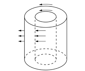
Considering the incompressible Newtonian fluid with the density ${\rho ^ * }$ (the superscript $*$ represents a dimensional parameter) and kinematic viscosity ${\nu ^ * }$ bounded by two infinitely long concentric porous cylinders, the schematic of the flow configuration together with the coordinate system is exhibited in figure 1. The inner and outer cylinders have radii $r_i^ *$, $r_o^ *$ and angular velocities $\varOmega _i^ *$, $\varOmega _o^ *$, respectively, and the radius ratio is $\eta = {{r_i^ * }/ {r_o^ * }}$. Let ${u^ * }$, ${v^ * }$ and ${w^ * }$ be the velocity components in the three directions of ${z^ * }$, ${r^ * }$ and ${\theta ^ * }$ in the cylindrical coordinate system, respectively, and ${p^ * }$ is the pressure. The oscillatory suction/blowing on the inner and outer cylinder walls are employed in the form $V_i^ * = {\varDelta ^ * }\cos ( {{\omega ^ * }{t^ * }} )$ and $V_o^ * = \eta {\varDelta ^ * }\cos ( {{\omega ^ * }{t^ * }} )$, respectively. Here ${\varDelta ^ * }$ and ${\omega ^ * }$ are the amplitude and frequency of the oscillatory suction/blowing, respectively. For infinitely long cylinders, mass conservation can be satisfied since we have $V_i^*r_i^*=V_o^*r_o^*$, i.e. the fluid flowing into and out of the gap between the cylinders cancels out. The governing equations of the flow are the Navier–Stokes equation and the continuity equation

(2.1a)\begin{gather} \frac{{{\rm D}{u^ * }}}{{{\rm D}{t^ * }}} ={-} \frac{1}{{{\rho ^ * }}}\frac{{\partial {p^ * }}}{{\partial {z^ * }}} + {\nu ^ * }{\nabla ^{ * 2}}{u^ * }, \end{gather}
(2.1b)\begin{gather}\frac{{{\rm D}{v^ * }}}{{{\rm D}{t^ * }}} - \frac{{{w^{ * 2}}}}{{{r^ * }}} ={-} \frac{1}{{{\rho ^ * }}}\frac{{\partial {p^ * }}}{{\partial {r^ * }}} + {\nu ^ * }\left( {{\nabla ^{ * 2}}{v^ * } - \frac{{{v^ * }}}{{{r^{ * 2}}}} - \frac{2}{{{r^{ * 2}}}}\frac{{\partial {w^ * }}}{{\partial {\theta ^ * }}}} \right), \end{gather}
(2.1c)\begin{gather}\frac{{{\rm D}{w^ * }}}{{{\rm D}{t^ * }}} + \frac{{{v^ * }{w^ * }}}{{{r^ * }}} ={-} \frac{1}{{{\rho ^ * }}}\frac{1}{{{r^ * }}}\frac{{\partial {p^ * }}}{{\partial {\theta ^ * }}} + {\nu ^ * }\left( {{\nabla ^{ * 2}}{w^ * } - \frac{{{w^ * }}}{{{r^{ * 2}}}} + \frac{2}{{{r^{ * 2}}}}\frac{{\partial {v^ * }}}{{\partial {\theta ^ * }}}} \right), \end{gather}
(2.1d)\begin{gather}\frac{1}{{{r^ * }}}\frac{\partial }{{\partial {r^ * }}}\left( {{r^ * }{v^ * }} \right) + \frac{1}{{{r^ * }}}\frac{{\partial {w^ * }}}{{\partial {\theta ^ * }}} + \frac{{\partial {u^ * }}}{{\partial {z^ * }}} = 0, \end{gather}

where

(2.2a)\begin{gather} \frac{{\rm D}}{{{\rm D}{t^ * }}} = \frac{\partial }{{\partial {t^ * }}} + {v^ * }\frac{\partial }{{\partial {r^ * }}} + \frac{{{w^ * }}}{{{r^ * }}}\frac{\partial }{{\partial {\theta ^ * }}} + {u^ * }\frac{\partial }{{\partial {z^ * }}}, \end{gather}
(2.2b)\begin{gather}{\nabla ^{ * 2}} = \frac{1}{{{r^ * }}}\frac{\partial }{{\partial {r^ * }}}\left( {{r^ * }\frac{\partial }{{\partial {r^ * }}}} \right) + \frac{1}{{{r^{ * 2}}}}\frac{{{\partial ^2}}}{{\partial {\theta ^{ * 2}}}} + \frac{{{\partial ^2}}}{{\partial {z^{ * 2}}}}, \end{gather}

and the boundary conditions are

(2.3a)\begin{gather} {u^ * } = 0,\quad{v^ * } = {\varDelta ^ * }\cos \left( {{\omega ^ * }{t^ * }} \right),\quad {w^ * } = \varOmega _i^ * r_i^ *\quad \text{at}\ {r^ * } = r_i^ * , \end{gather}
(2.3b)\begin{gather}{u^ * } = 0,\quad {v^ * } = \eta {\varDelta ^ * }\cos \left( {{\omega ^ * }{t^ * }} \right),\quad {w^ * } = \varOmega _o^ * r_o^ *\quad \text{at}\ {r^ * } = r_o^ * . \end{gather}

Figure 1. Schematic of the flow configuration.

The characteristic scales for length, velocity, time and pressure are taken as ${d^ * } = r_o^ * - r_i^ *$, ${\nu ^ * }/{d^ * }$, ${d^{ * 2}}/{\nu ^ * }$ and ${\rho ^ * }{( {\nu ^ * }/{d^ * } )^2}$, respectively (Dubrulle et al. Reference Dubrulle, Dauchot, Daviaud, Longaretti, Richard and Zahn2005; Maretzke, Hof & Avila Reference Maretzke, Hof and Avila2014; Wang et al. Reference Wang, Ayats, Deguchi, Mellibovsky and Meseguer2022). The inner and outer cylinder Reynolds numbers are defined as $R{e_i} = {\varOmega _i^ * r_i^ * {d^ * }}/{\nu ^ * }$ and $R{e_o} = {\varOmega _o^ * r_o^ * {d^ * }}/{\nu ^ * }$, respectively. Additionally, to measure the relative magnitude of the suction/blowing modulation, we use the velocity and angular velocity of the inner cylinder as the dimensionless scales for the suction/blowing amplitude and frequency, respectively, resulting in $\varDelta = {\varDelta ^ * }/( {\varOmega _i^ * r_i^ * } )$ and $\omega = {\omega ^ * }/\varOmega _i^ *$. Additional dimensionless numbers include the inner and outer cylinder radii, denoted as ${r_i} = {r_i}^ * /{d^ * } = \eta /( {1 - \eta } )$ and ${r_o} = r_{o}^{*} /{d^ * } = 1 /( {1 - \eta } )$, respectively, and the ratio of the angular velocities $\mu = \varOmega _o^ * /\varOmega _i^ * = \eta R{e_o}/R{e_i}$. In the following, the superscript $*$ is dropped for dimensionless variables.

The periodic basic flow has the form

(2.4ad)\begin{equation} U = 0,\quad V = \tilde{\varDelta} \cos \left( {\tilde{\omega} t} \right)/r,\quad W = W\left( {r,t} \right),\quad P = P\left( {r,t} \right), \end{equation}

where $\tilde {\varDelta } = {r_i}R{e_i}\varDelta$, $\tilde {\omega } = ( {R{e_i}/{r_i}} )\omega$, $W( {r,t + 2{\rm \pi} /\tilde {\omega } } ) = W( {r,t} )$, and (2.4ad) satisfies the dimensionless form of the continuity equation (2.1d). Here $\tilde {\varDelta }$ and $\tilde {\omega }$ represent the amplitude and frequency of the modulation normalized in viscous units, $\nu ^*/r_i^*$ and $\nu ^*/d^{*2}$, respectively. Then, substituting (2.4ad) into (2.1) and (2.3) gives the governing equation and boundary conditions for the circumferential velocity $W( {r,t} )$,

(2.5a)\begin{gather} \frac{{\partial W}}{{\partial t}} + \frac{{{\tilde{\varDelta} }\cos \left( {\tilde{\omega} t} \right)}}{r}\left( {\frac{{\partial W}}{{\partial r}} + \frac{W}{r}} \right) = \frac{{{\partial ^2}W}}{{\partial {r^2}}} + \frac{1}{r}\frac{{\partial W}}{{\partial r}} - \frac{W}{{{r^2}}}, \end{gather}
(2.5b)\begin{gather}W\left( {{r_i},t} \right) = R{e_i},\quad W\left( {{r_o},t} \right) = R{e_o}. \end{gather}

Since the problem (2.5) has no analytical solutions, a numerical approach must be employed. Specifically, considering the pure Taylor–Couette flow, i.e. $\tilde {\varDelta } = 0$, an analytical solution can be obtained as

(2.6)\begin{equation} {W_0}\left( r \right) = {W_A}r + W_B / r, \end{equation}

where ${W_A} = {r_o}^{ - 1}( {R{e_o} - \eta R{e_i}} )/( {1 - {\eta ^2}} )$ and ${W_B} = {r_i}( {R{e_i} - \eta R{e_o}} )/( {1 - {\eta ^2}} )$. In the present work, we use $\eta$, $\mu$, $R{e_i}$, $\varDelta$ and $\omega$ as independent dimensionless parameters. In particular, the numerical results will be presented using $\varDelta$ and $\omega$ rather than $\tilde {\varDelta }$ and $\tilde {\omega }$.

2.1. Numerical solution

Standard Chebyshev polynomials defined in the range $[ { - 1,1} ]$ are used for discretization in the radial direction. The domain $[ {{r_i},{r_o}} ]$ is mapped onto $[ { - 1,1} ]$ using the transformation $r = Ex + F$, where $E = ( {{r_o} - {r_i}} )/2$ and $F = E + {r_i}$. It turns out that the circumferential velocity can be expressed as

(2.7)\begin{equation} W\left( {x,t} \right) = {W_0}\left( {Ex + F} \right) + {W_A}\sum_{m ={-} \infty }^{ + \infty } {{A_m}\left( x \right) {\rm e}^{{\rm i}m\tilde{\omega} t}}, \end{equation}

where ${W_0}$ represents the circumferential velocity distribution without wall suction/blowing and is given by (2.6). Moreover, $i = \sqrt { - 1}$ and ${A_m}( x ) = {\bar {A}_{ - m}}( x )$ in order for $W$ to be real, where a bar denotes a complex conjugate. Substituting (2.7) into (2.5a) and separating Fourier components, we obtain

(2.8a)\begin{align} & {\rm i}m\tilde{\omega} {E^2}{\left( {Ex + F} \right)^2}{A_m} + \left( {{E^2}{A_m} - E\left( {Ex + F} \right)\frac{{{\rm d}{A_m}}}{{{\rm d}\kern 0.06em x}} - {{\left( {Ex + F} \right)}^2}\frac{{{{\rm d}^2}{A_m}}}{{{\rm d}\kern 0.06em {x^2}}}} \right)\nonumber\\ &\qquad + \frac{{{\tilde{\varDelta} }}}{2} \left( {{E^2}\left( {{A_{m - 1}} + {A_{m + 1}}} \right) + E\left( {Ex + F} \right)\left( {\frac{{{\rm d}{A_{m - 1}}}}{{{\rm d}\kern 0.06em x}} + \frac{{{\rm d}{A_{m + 1}}}}{{{\rm d}\kern 0.06em x}}} \right)} \right) \nonumber\\ &\quad ={-} {\tilde{\varDelta} } {E^2}\left( {Ex + F} \right)\left( {{\delta _{m , 1}} + {\delta _{m , - 1}}} \right),\quad\left( {m = 0, \pm 1, \pm 2, \ldots , \pm \infty } \right), \end{align}

where ${\delta _{p,q}}$ is the Kronecker delta. The boundary conditions corresponding to (2.5b) are

(2.8b)\begin{equation} {A_m}\left( { \pm 1} \right) = 0 \quad \left( {m \in \mathbb{Z}} \right). \end{equation}

One can easily verify that $A_m$ is independent of $W_A$. In the actual calculation process, we only retain the first $M$ Fourier modes in (2.7), that is, ${A_{ \pm m}}( x ) = 0$ $( {m > M} )$. In this way, (2.8a) becomes a differential system composed of $2M+1$ coupled ordinary differential equations. It should be noted that although the condition ${A_m}( x ) = {\bar {A}_{ - m}}( x )$ can be used to reduce the number of differential equations to $M + 1$, this approach is not adopted here because the time required to calculate the basic flow can be ignored compared with the stability equation. Alternatively, this condition can serve as a validation of the calculation results. We use the Chebyshev–Galerkin spectral method to solve the $2M + 1$ ordinary differential equations of (2.8).

The effectiveness of the above method depends on the convergence speed of the Fourier series, which means that the energy contained in the higher harmonics should decay rapidly with the degree of the harmonic. The energy of the $m$th mode is defined as

(2.9)\begin{equation} {E_m} = \frac{{2 - {\delta _{m,0}}}}{4}\int_{ - 1}^1 {{{\left| {{A_m}\left( x \right)} \right|}^2}\,{{\rm d}\kern 0.06em x}} \quad \left( {m \in \mathbb{N}} \right). \end{equation}

Figure 2 shows the variation of energy contained in the first six Fourier components with the amplitude $\varDelta$ at $\eta = 0.5$, $R{e_i} = 100$ and $\omega = 1$. It can be seen that ${E_m}$ rapidly decays with the growth of $m$. Therefore, calculating the basic flow does not require a large $M$ value. In the present work, $M = 5$ to $10$ can ensure sufficient computational accuracy.

Figure 2. Variations of the energy for the basic flow versus the amplitude $\varDelta$ for $\eta = 0.5$, $R{e_i} = 100$ and $\omega = 1$.

Note that the introduction of the oscillatory wall suction/blowing modulation would change the flow rate with respect to that of the pure Taylor–Couette flow driven by the same cylinder wall angular velocity. Figure 3(a) shows the difference of the mean flow modulated by the oscillatory wall suction/blowing and that of the pure Taylor–Couette flow. It can be seen that there are Stokes layers near both cylinder walls, which is caused by the oscillating wall modulation. The characteristic thickness of the Stokes layer is given in dimensionless form by ${d_s} = \sqrt {2{\nu ^ * }/{\omega ^ * }} /{d^ * } = \sqrt {2{r_i}/( {\omega R{e_i}} )} = \sqrt {2/\tilde {\omega }}$. For the parameters considered, we have $d_s=0.14$, which is marked by the dashed lines in figure 3(a), where it is seen that $d_s$ is roughly half of the distance from the location of the maxima to the wall. The change of the flow rate can be confirmed by

(2.10)\begin{equation} {f_d}\left( t \right) = \int_{{r_i}}^{{r_o}} {\left( {W\left( {r,t} \right) - {W_0}\left( r \right)} \right)} \,{\rm d}r, \end{equation}

which is shown in figure 3(b), where $f_d$ changes periodically.

Figure 3. Properties of the basic flow at $\eta = 0.5$, $R{e_i} = 100$, $\varDelta =0.02$ and $\omega = 1$. ($a$) Contour lines of $( {W - {W_0}} )/{W_A}$; ($b$) a comparison of numerical and asymptotic results for the flow rate of a modulated Taylor–Couette flow.

The basic flow and the flow rate for the case of steady suction/blowing can be derived by substituting $\tilde {\omega } = 0$ into (2.5), yielding

(2.11a) \begin{equation} W\left( r \right) = \begin{cases} \dfrac{ Re_o - \eta Re_i }{r_o^{ 1 + {\tilde{\varDelta} }}\left( {1 - {\eta ^{2 + {\tilde{\varDelta} }}}} \right)}\left( {{r^{1 + {\tilde{\varDelta} }}} - \dfrac{{r_i^{2 + {\tilde{\varDelta} }}}}{r}} \right) + R{e_i}\dfrac{{{r_i}}}{r}, & {{\tilde{\varDelta} } \ne - 2,} \\ {\dfrac{{R{e_o} - \eta R{e_i}}}{{rr_o^{ - 1}\ln \eta }}\ln \dfrac{{{r_i}}}{r} + R{e_i}\dfrac{{{r_i}}}{r},} & {{\tilde{\varDelta} } ={-} 2.} \end{cases} \end{equation}

Using (2.10), we obtain

(2.11b)\begin{equation} {f_d} = \begin{cases} {{W_A}r_o^2\left( {\left( {1 - {\eta ^2}} \right)\left( {\dfrac{1}{{2 + {\tilde{\varDelta} }}} - \dfrac{1}{2} + \dfrac{{\ln \eta }}{{1 - {\eta ^{2 + {\tilde{\varDelta} }}}}}} \right) - \ln \eta } \right),} & {{\tilde{\varDelta} } \ne - 2,} \\ {{W_A}r_o^2\left( {\left( {1 - {\eta ^2}} \right)\dfrac{{\ln \eta - 1}}{2} - \ln \eta } \right),} & {{\tilde{\varDelta} } ={-} 2.} \end{cases} \end{equation}

When ${W_A} \ne 0$, it can be proved that $f_d/W_A$ is a monotonically decreasing function of $\tilde {\varDelta }$. Therefore, compared with the case without suction/blowing, the flow rate increases when $W_A \tilde {\varDelta }<0$ and decreases when $W_A \tilde {\varDelta }>0$.

2.2. Asymptotic solution

Asymptotic solutions can be obtained when the wall suction/blowing is weak enough, i.e. $| \tilde {\varDelta } | \ll 1$. The asymptotic solution can be written in the following form:

(2.12)\begin{equation} W\left( {r,t} \right) = {W_0}\left( {r,t} \right) + {W_1}\left( {r,t} \right){\tilde{\varDelta} } + {W_2}\left( {r,t} \right){\tilde{\varDelta} }^2 + O\left( {{\tilde{\varDelta} }^3} \right). \end{equation}

Substituting (2.12) into (2.5) yields the equations satisfied by the coefficients ${W_m}( {r,t} )$ for each order of $\tilde {\varDelta }$,

(2.13a)\begin{gather} \frac{{\partial {W_0}}}{{\partial t}} - \left( {\frac{{{\partial ^2}{W_0}}}{{\partial {r^2}}} + \frac{1}{r}\frac{{\partial {W_0}}}{{\partial r}} - \frac{{{W_0}}}{{{r^2}}}} \right) = 0, \end{gather}
(2.13b)\begin{gather}\frac{{\partial {W_1}}}{{\partial t}} - \left( {\frac{{{\partial ^2}{W_1}}}{{\partial {r^2}}} + \frac{1}{r}\frac{{\partial {W_1}}}{{\partial r}} - \frac{{{W_1}}}{{{r^2}}}} \right) ={-} \frac{{\cos \left( {\tilde{\omega} t} \right)}}{r}\left( {\frac{{\partial {W_0}}}{{\partial r}} + \frac{{{W_0}}}{r}} \right), \end{gather}
(2.13c)\begin{gather}\frac{{\partial {W_2}}}{{\partial t}} - \left( {\frac{{{\partial ^2}{W_2}}}{{\partial {r^2}}} + \frac{1}{r}\frac{{\partial {W_2}}}{{\partial r}} - \frac{{{W_2}}}{{{r^2}}}} \right) ={-} \frac{{\cos \left( {\tilde{\omega} t} \right)}}{r}\left( {\frac{{\partial {W_1}}}{{\partial r}} + \frac{{{W_1}}}{r}} \right), \end{gather}

and the corresponding boundary conditions are

(2.13d)\begin{equation} {W_m}\left( {{r_i},t} \right) = R{e_i}{\delta _{m,0}},\quad {W_m}\left( {{r_o},t} \right) = R{e_o}{\delta _{m,0}}\quad \left( {m = 0,1,2} \right). \end{equation}

The solution of (2.13a) and (2.13d) corresponds to the circumferential velocity of the steady Taylor–Couette flow, which is independent of time, i.e. ${W_0}( {r,t} ) = {W_0}( r )$, and its expression is given in (2.6). Furthermore, substituting it into (2.13b) and (2.13d), we have ${W_1}( {r,t} )$ with the form

(2.14a)\begin{equation} {W_1}\left( {r,t} \right) = {W_{1+}}\left( r \right){{\rm e}^{{\rm i}\tilde{\omega} t}} + {W_{1-}}\left( r \right){{\rm e}^{ - {\rm i}\tilde{\omega} t}}, \end{equation}

and

(2.14b)\begin{equation} {W_{1+}}\left( r \right) = \frac{{{W_A}}}{{{\beta ^2}}}\left( {A{{\rm J}_1}\left( {{\rm i}\beta r} \right) + B{{\rm Y}_1}\left( { - {\rm i}\beta r} \right) - \frac{1}{r}} \right),\quad {W_{1-}}\left( r \right) = {\bar{W}_{1+}}\left( r \right), \end{equation}

where $\beta = \sqrt {{\rm i}\tilde {\omega } }$, ${{\rm J}_\nu }( x )$ and ${{\rm Y}_\nu }( x )$ are the Bessel functions of the first and second types of order $\nu$, respectively,

(2.14c)\begin{gather} A ={-} \frac{{{{\rm Y}_1}\left( { - {\rm i}\beta {r_i}} \right)/{r_o} - {{\rm Y}_1}\left( { - {\rm i}\beta {r_o}} \right)/{r_i}}}{{B{e_\beta }\left( {{r_i},{r_o}} \right)}},\quad B = \frac{{{{\rm J}_1}\left( {{\rm i}\beta {r_i}} \right)/{r_o} - {{\rm J}_1}\left( {{\rm i}\beta {r_o}} \right)/{r_i}}}{{B{e_\beta }\left( {{r_i},{r_o}} \right)}}, \end{gather}
(2.14d)\begin{gather}B{e_\beta }\left( {x,y} \right) = {{\rm J}_1}\left( {{\rm i}\beta x} \right){{\rm Y}_1}\left( { - {\rm i}\beta y} \right) - {{\rm J}_1}\left( {{\rm i}\beta y} \right){{\rm Y}_1}\left( { - {\rm i}\beta x} \right). \end{gather}

Similar to (2.13c), (2.13d) and (2.14), the expression for ${W_2}( {r,t} )$ can be obtained as

(2.15a)\begin{equation} {W_2}\left( {r,t} \right) = {W_{20}}\left( r \right) + {W_{2+}}\left( r \right){{\rm e}^{2{\rm i}\tilde{\omega} t}} + {W_{2-}}\left( r \right){{\rm e}^{ - 2{\rm i}\tilde{\omega} t}},\end{equation}

and

(2.15b)\begin{gather} {W_{20}}\left( r \right) = {W_A}\left( {{H_1}\left( r \right) - \frac{{{r_o}}}{r}\frac{{{r^2} - {r_i}^2}}{{r_o^2 - r_i^2}}{H_1}\left( {{r_o}} \right)} \right), \end{gather}
(2.15c)\begin{gather}{W_{2+}}\left( r \right) = \frac{{{W_A}}}{2}\left( {{H_2}\left( r \right) - \frac{{B{e_\beta }\left( {\sqrt 2 {r_i},\sqrt 2 r} \right)}}{{B{e_\beta }\left( {\sqrt 2 {r_i},\sqrt 2 {r_o}} \right)}}{H_2}\left( {{r_o}} \right)} \right),\quad {W_{2-}}\left( r \right) = {\bar{W}_{2+}}\left( r \right), \end{gather}

where

(2.15d)\begin{gather} {H_1}\left( r \right) = {{\rm Re}} \left( {\frac{r}{{{\beta ^2}}}\int_{{r_i}}^r {\frac{{A{{\rm J}_1}\left( {{\rm i}\beta \xi } \right) + B{{\rm Y}_1}\left( { - {\rm i}\beta \xi } \right)}}{{{\xi ^2}}}{\rm d}\xi } } \right), \end{gather}
(2.15e)\begin{gather}{H_2}\left( r \right) = \int_{{r_i}}^r {\frac{{B{e_\beta }\left( {\sqrt 2 r,\sqrt 2 \xi } \right)}}{{{\beta ^2}\xi }}\frac{{\rm d}}{{{\rm d}\xi }}\left( {A\xi {{\rm J}_1}\left( {{\rm i}\beta \xi } \right) + B\xi {{\rm Y}_1}\left( { - {\rm i}\beta \xi } \right)} \right){\rm d}\xi }, \end{gather}

where ${{\rm Re}}( C )$ denotes the real part of the complex number $C$ and a prime indicates the first derivative.

The variation of $W_{20}$ for $\eta = 0.5$, ${R{e_i}} = 197.885$, $\omega = 1$ and for $\eta = 0.95$, ${R{e_i}} = 184.986$, $\omega = 10$ is shown in figure 4(a). In § 4, it will be seen that $W_{20}$ plays a crucial role in altering the flow stability. Substituting (2.12) and (2.14) into (2.10), we obtain an asymptotic expression for the flow rate

(2.16)\begin{equation} {f_d}\left( t \right) = 2\exp({{{\rm Re}}\left( {\ln {f_{d11}}} \right)})\cos \left( {\tilde{\omega} t + {{\rm Im}} \left( {\ln {f_{d11}}} \right)} \right){\tilde{\varDelta} } + O\left( {{\tilde{\varDelta} }^2} \right), \end{equation}

where ${f_{d11}} = \int _{{r_i}}^{{r_o}} {{W_{11}}( r )\,{\rm d}r}$ and ${{\rm Im}} ( C )$ denotes the imaginary part of the complex number $C$. It can be seen that the phase of ${f_d}( t )$ is ahead of the radial velocity by $2{\rm \pi} \{ {{{\rm Im}} ( {\ln {f_{d11}}} )/( {2{\rm \pi} } )} \}$, where $\{ {\cdot } \}$ represents the fractional part of a real number. Here, it should be pointed out that theoretically, the basic flow has the above asymptotic form only when the following condition is satisfied:

(2.17)\begin{equation} \left| {{\tilde{\varDelta} }} \right|/\tilde{\omega} \ll 1\quad \text{or}\ \quad \left| {\varDelta } \right|/\omega \ll 1 \end{equation}

for fixed $\eta$. Upon careful inspection of (2.14) and (2.15), it can be observed that ${W_1}{\tilde {\varDelta } } \sim O( {{\varDelta }/\omega } )$ and ${W_2}{\tilde {\varDelta } }^2 \sim O( {{\varDelta }^2/\omega } )$. Therefore, in addition to $| {{\tilde {\varDelta } }} | \ll 1$, the condition (2.17) must be satisfied. The comparison between the numerical and asymptotic velocity profiles for the modulated Taylor–Couette flow is shown in figure 4(b) for $\eta = 0.5$, ${R{e_i}} = 100$, $\varDelta = 0.02$, $\omega = 1$ and $\tilde {\omega } t = 1.445{\rm \pi}$. The results indicate that the asymptotic solution is in good agreement with the numerical solution.

Figure 4. ($a$) Variation of ${W_{20}}/{W_A}$ for $\eta = 0.5$, ${R{e_i}} = 197.885$, $\omega = 1$: ———, and for $\eta = 0.95$, ${R{e_i}} = 184.986$, $\omega = 10$ : $-----$; ($b$) a comparison of the asymptotic and numerical results of $( {W - {W_0}} )/{W_A}$ at $\tilde {\omega } t =1.445{\rm \pi}$, corresponding to the maximum in figure 3(b). Other parameters are $\eta = 0.5$, ${R{e_i}} = 100$, $\varDelta = 0.02$ and $\omega = 1$.

3. Stability problem

The basic state (2.4ad) is infinitesimally disturbed as

(3.1)\begin{equation} \left( {u,v,w,p} \right) = \left( {U,V,W,P} \right) + \varepsilon \left({u',v',w',p'}\right), \end{equation}

where $| \varepsilon | \ll 1$. The base state is independent of $z$ and $\theta$. Therefore, the following form of disturbances can be considered:

(3.2)\begin{equation} \left[ {\begin{array}{@{}c@{}} {u'\left( {z,r,\theta ,t} \right)}\\ {v'\left( {z,r,\theta ,t} \right)}\\ {w'\left( {z,r,\theta ,t} \right)}\\ {p'\left( {z,r,\theta ,t} \right)} \end{array}} \right] = {{\rm Re}} \left\{ \left[ {\begin{array}{@{}c@{}}{\hat{u}\left( {r,t} \right)}\\ {\hat{v}\left( {r,t} \right)}\\ {\hat{w}\left( {r,t} \right)}\\ {\hat{p}\left( {r,t} \right)} \end{array}} \right]{\exp({{\rm i}( {az + n\theta } )})} \right\}. \end{equation}

Here $a \in \mathbb {R}$ and $n \in \mathbb {Z}$ are the wavenumbers of the disturbance wave along the $z$ and $\theta$ directions, respectively. It can be shown that the governing equations and boundary conditions for the stability problem are

(3.3a)\begin{gather} \left( {\begin{array}{@{}cc@{}} J & 0\\ 0 & {{k^2}{r^2}} \end{array}} \right)\frac{\partial }{{\partial t}}\left( {\begin{array}{@{}c@{}} {\hat{\varPhi} }\\ {\hat{\varOmega} } \end{array}} \right) = \left( {\begin{array}{@{}cc@{}} {{L_{11}}} & {{L_{12}}}\\ {{L_{21}}} & {{L_{22}}} \end{array}} \right)\left( {\begin{array}{@{}c@{}} {\hat{\varPhi} }\\ {\hat{\varOmega} } \end{array}} \right), \end{gather}
(3.3b)\begin{gather}\hat{\varPhi} = \frac{{\partial \hat{\varPhi} }}{{\partial r}} = \hat{\varOmega} = 0\quad \text{at}\ r = r_i\ {\rm and}\ r = r_o , \end{gather}

where the definitions of the symbols and the detailed derivation of the formulas are given in Appendix A.

The operators $L$ on the right-hand side of (3.3a) depend on the periodic basic flow. According to the Floquet theory, the solutions of (3.3) have the form

(3.4)\begin{equation} \left( {\begin{array}{@{}c@{}} {{{\hat{\varPhi} }_j}\left( {r,t} \right)}\\ {{{\hat{\varOmega} }_j}\left( {r,t} \right)} \end{array}} \right) = {{\rm e}^{{\sigma _j}t}}\left( {\begin{array}{@{}c@{}} {{\phi _j}\left( {r,t} \right)}\\ {{\zeta _j}\left( {r,t} \right)} \end{array}} \right)\quad \left(\kern 1.5pt {j = 1,2, \ldots } \right), \end{equation}

where ${\phi _j}$ and ${\zeta _j}$ are both periodic functions of time and have the same period as the basic flow. Here, ${\sigma _j}$ are the complex Floquet exponents, whose real parts are the perturbation growth rates. The subscript $j$ represents different Floquet modes, which are sorted according to the principle of decreasing growth rate to maximize the real part of ${\sigma _1}$. If ${{\rm Re}}( {{\sigma _1}} ) < 0$ then the basic flow is asymptotically stable for infinitesimal disturbances; on the contrary, the flow is unstable if ${{\rm Re}}( {{\sigma _1}} ) > 0$.

3.1. Numerical procedure

We left multiply the invertible matrix ${\rm diag}({{k^8}{r^{12}},{k^4}{r^6}} )$ in (3.3a) to eliminate the denominator, and express the unknowns as basis function expansions, i.e.

(3.5a)\begin{gather} \hat{\varPhi} \left( {r,t} \right) = \sum_{l = 0}^{ + \infty } {{G_{1l}}\left( t \right){\varphi _{1l}}\left( x \right)} \approx \sum_{l = 0}^{{{\rm K}_1} - 4} {{G_{1l}}\left( t \right){\varphi _{1l}}\left( x \right)}, \end{gather}
(3.5b)\begin{gather}\hat{\varOmega} \left( {r,t} \right) = \sum_{l = 0}^{ + \infty } {{G_{2l}}\left( t \right){\varphi _{2l}}\left( x \right)} \approx \sum_{l = 0}^{{{\rm K}_2} - 2} {{G_{2l}}\left( t \right){\varphi _{2~l}}\left( x \right)}, \end{gather}

where ${G_{1l}}( t )$ and ${G_{2l}}( t )$ are basis function coefficients, and the two basis functions are

(3.6a)\begin{gather} {\varphi _{1l}}\left( x \right) = {T_l}\left( x \right) + {a_l}{T_{l + 2}}\left( x \right) + {b_l}{T_{l + 4}}\left( x \right),\quad \left( {l = 0,1,2, \ldots ,{{\rm K}_1} - 4} \right), \end{gather}
(3.6b)\begin{gather}{\varphi _{2l}}\left( x \right) = {T_l}\left( x \right) - {T_{l + 2}}\left( x \right),\quad \left( {l = 0,1,2, \ldots ,{{\rm K}_2} - 2} \right), \end{gather}

respectively, where ${T_l}( x )$ denotes the $l$th order Chebyshev polynomial of the first kind and ${a_l} = - 2 + 2/( {l + 3} )$, ${b_l} = - 1 - {a_l}$. The expansions are truncated to orders ${{\rm K}_1} - 4$ and ${{\rm K}_2} - 2$ for $\hat {\varPhi } ( {r,t} )$ and $\hat {\varOmega } ( {r,t} )$, respectively, and the selection of basis functions has taken into account the boundary conditions (3.3b). Substituting (3.5) into (3.3a) and applying the Galerkin spectral method gives the coefficient matrix of the differential system; see Appendix C for the calculation method of the Chebyshev inner product.

Now (3.3) can be represented by a set of ordinary equations, which have the form

(3.7)\begin{equation} \boldsymbol{M}\frac{{{\rm d}{\boldsymbol{\psi }}}}{{{\rm d}t}} = \boldsymbol{ L}\left( t \right){\boldsymbol{\psi }},\end{equation}

where ${\boldsymbol {\psi }}( t ) = {( {{G_{1,0}}( t ), \ldots,{G_{1,{{\rm K}_1} - 4}}( t ),{G_{2,0}}( t ), \ldots,{G_{2,{{\rm K}_2} - 2}}( t )} )^{\rm T}}$, the superscript T represents the transpose of the matrix, $\boldsymbol { M}$ and $\boldsymbol { L}( t )$ are $( {{{\rm K}_1} + {{\rm K}_2} - 4} )$-order square matrixes with the latter $2{\rm \pi} /\tilde {\omega }$ periodic in $t$. To obtain the Floquet exponents, it is necessary to consider a more general form of (3.7),

(3.8)\begin{equation} \boldsymbol{M}\frac{{{\rm d}{\boldsymbol{\varPsi }}}}{{{\rm d}t}} = \boldsymbol{ L}\left( t \right){\boldsymbol{\varPsi }}, \end{equation}

where ${\boldsymbol {\varPsi }}( t )$ is a $( {{{\rm K}_1} + {{\rm K}_2} - 4} )$-order square matrix composed of solution vectors. According to Floquet theory, (3.8) has the basic solution matrix in the form

(3.9)\begin{equation} {\boldsymbol{\varPsi}}\left( t \right) = \boldsymbol{ P}\left( t \right){{\rm e}^{t\boldsymbol{ Q}}}, \end{equation}

where $\boldsymbol { P}( t )$ is a $( {{{\rm K}_1} + {{\rm K}_2} - 4} )$-order square matrix with a period of $2{\rm \pi} /\tilde {\omega }$, $\boldsymbol { Q}$ is a $( {{{\rm K}_1} + {{\rm K}_2} - 4} )$-order constant square matrix, whose eigenvalues are the Floquet exponents ${\sigma _j}$. Without loss of generality, let the initial value of ${\boldsymbol {\varPsi }}$ be the identity matrix, i.e. ${\boldsymbol {\varPsi }}( 0 ) = {\boldsymbol {I}}$. Obviously, we can easily obtain ${\boldsymbol {\varPsi }}( {2{\rm \pi} /\tilde {\omega } } ) = {{\rm e}^{2{\rm \pi} {\boldsymbol {Q}}/\tilde {\omega } }}$. If the eigenvalues of ${\boldsymbol {\varPsi }}( {2{\rm \pi} /\tilde {\omega } } )$ are set to ${\lambda _j}$, then the Floquet exponents ${\sigma _j}$ can be obtained by the following equation:

(3.10)\begin{equation} {\sigma _j} = \frac{\tilde{\omega} }{{2{\rm \pi} }}\ln {\lambda _j},\quad \left(\kern 1.5pt {j = 1,2, \ldots ,{{\rm K}_1} + {{\rm K}_2} - 4} \right). \end{equation}

To ensure computational accuracy, the time integration of the numerical method for solving (3.8) to obtain ${\boldsymbol {\varPsi }}( {2{\rm \pi} /\tilde {\omega } } )$ adopts the fourth-order Runge–Kutta method.

Figure 5 illustrates spectral convergence of the method as the degrees of freedom in the approximation increase. We have used the same value of the orders of Chebyshev polynomials to calculate the basic flow and the disturbances, i.e. ${\rm K}_1={\rm K}_2=K$. It can be seen that the influence of the Chebyshev truncation number $K$ is not significant, and even the results of $K = 20$ are satisfactory. There is a significant error in the results when $M = 1$, indicating that the high-frequency component of the basic flow plays an important role in the disturbance growth rate. Generally, more Fourier modes and Chebyshev expression truncation numbers are needed for higher amplitude $| \varDelta |$ and lower frequency $\omega$ of the modulation. Typically $K = 20$ to $30$, $M = 5$ to $10$ are used in our calculations.

Figure 5. The relative deviation $| {{{\rm Re}} ( {\sigma _1^{M,K}} ) - {{\rm Re}} ( {\sigma _1^{20,50}} )} |/| {{{\rm Re}} ( {\sigma _1^{20,50}} )} |$ of maximum growth rate ${{\rm Re}} ( {{\sigma _1}} )$ for $\mu = 0$, $\eta = 0.5$, $a = 3$, $n = 1$, $R{e_i} = 100$, $\varDelta = 0.1$, $\omega = 1$ for different numbers of Fourier modes $M$ in (2.7) and radial Chebyshev truncation numbers $K( {K = {{\rm K}_1} = {{\rm K}_2}} )$ in (3.5).

3.2. Asymptotic analysis

If the wall suction/blowing amplitude is very small ($| \tilde {\varDelta } | \ll 1$), we can perform an asymptotic analysis of the flow stability using the expansions

(3.11a)\begin{gather} {\sigma _j} = {\sigma _{j0}} + {\sigma _{j1}}{\tilde{\varDelta} } + {\sigma _{j2}}{\tilde{\varDelta} }^2 + O\left( {{\tilde{\varDelta} }^3} \right), \end{gather}
(3.11b)\begin{gather}{\phi _j}\left( {r,t} \right) = {\phi _{j0}}\left( r \right) + {\phi _{j1}}\left( {r,t} \right){\tilde{\varDelta} } + {\phi _{j2}}\left( {r,t} \right){\tilde{\varDelta} }^2 + O\left( {{\tilde{\varDelta} }^3} \right), \end{gather}
(3.11c)\begin{gather}{\zeta _j}\left( {r,t} \right) = {\zeta _{j0}}\left( r \right) + {\zeta _{j1}}\left( {r,t} \right){\tilde{\varDelta} } + {\zeta _{j2}}\left( {r,t} \right){\tilde{\varDelta} }^2 + O\left( {{\tilde{\varDelta} }^3} \right), \end{gather}

where ${\phi _{js}}( {r,t} )$ and ${\zeta _{js}}( {r,t} )$ $( {s = 1,2} )$ are $2{\rm \pi} /\tilde {\omega }$ periodic in time $t$. Substituting (2.12), (3.4), (3.11) and $V = {V_1}{\tilde {\varDelta } }$ into (3.3), where ${V_1} = {\cos (\tilde {\omega } t})/r$, collecting terms of equal powers in $\tilde {\varDelta }$, we obtain a series of equations, and the corresponding boundary conditions are

(3.12)\begin{equation} {\phi _{js}} = \frac{{\partial {\phi _{js}}}}{{\partial r}} = {\zeta _{js}} = 0,\quad \text{at}\ r = {r_i}\ {\rm and}\ r = {r_o}\quad \left( {s = 0,1,2} \right). \end{equation}

The leading-order equation simply controls the stability of the pure Taylor–Couette flow, and its form is

(3.13)\begin{equation} {\sigma _{j0}}\left( {\begin{array}{@{}cc@{}} J & 0\\ 0 & {{k^2}{r^2}} \end{array}} \right)\left( {\begin{array}{@{}c@{}} {{\phi _{j0}}}\\ {{\zeta _{j0}}} \end{array}} \right) = \left( {\begin{array}{@{}cc@{}} {L_{11}^0} & {L_{12}^0}\\ {L_{21}^0} & {L_{22}^0} \end{array}} \right)\left( {\begin{array}{@{}c@{}} {{\phi _{j0}}}\\ {{\zeta _{j0}}} \end{array}} \right), \end{equation}

where $L_{pq}^0$ $( {p,q = 1,2} )$ are given in Appendix B. From (3.12) $( s=0 )$ and (3.13), ${\sigma _{j0}}$ and ${( {{\phi _{j0}},{\zeta _{j0}}} )^{\rm T}}$ can be obtained. The adjoint eigenvector ${( {{\xi _{j0}},{\gamma _{j0}}} )^{\rm T}}$ of ${( {{\phi _{i0}},{\zeta _{i0}}} )^{\rm T}}$ will be needed. Left multiplying (3.13) by $( {{{\bar {\xi }}_{j0}},{{\bar {\gamma }}_{j0}}} )$ and integrating over $[ {{r_i},{r_o}} ]$, using integration by parts, the boundary condition (3.12) $( s=0 )$ and the boundary condition

(3.14)\begin{equation} {\xi _{j0}} = \frac{{\partial {\xi _{j0}}}}{{\partial r}} = {\gamma _{j0}} = 0,\quad \text{at}\ r = {r_i}\ {\rm and}\ r = {r_o}, \end{equation}

we obtain the adjoint equation of (3.13),

(3.15)\begin{equation} {\bar{\sigma}_{j0}}\left( {\begin{array}{@{}cc@{}} {{J^ + }} & 0\\ 0 & {{k^2}{r^2}} \end{array}} \right)\left( {\begin{array}{@{}c@{}} {{\xi _{j0}}}\\ {{\gamma _{j0}}} \end{array}} \right) = \left( {\begin{array}{@{}cc@{}} {L_{11}^{0 + }} & {L_{21}^{0 + }}\\ {L_{12}^{0 + }} & {L_{22}^{0 + }} \end{array}} \right)\left( {\begin{array}{@{}c@{}} {{\xi _{j0}}}\\ {{\gamma _{j0}}} \end{array}} \right), \end{equation}

where ${J^ + }$ and $L_{pq}^{0 + }$ $( {p,q = 1,2} )$ are given in Appendix B. Note that the eigenvalues in (3.13) and (3.15) are mutually conjugated, which is employed for verifying the accuracy of the present calculations. The process of deriving (3.15) from (3.12) to (3.14) reveals that the eigenvectors ${( {{\xi _{j0}},{\gamma _{j0}}} )^{\rm T}}$ and ${( {{\phi _{i0}},{\zeta _{i0}}} )^{\rm T}}$ satisfy the following orthogonality condition:

(3.16)\begin{equation} \int_{{r_i}}^{{r_o}} {{{\left( {\begin{array}{@{}c@{}} {{{\bar{\xi}}_{j0}}}\\ {{{\bar{\gamma}}_{j0}}} \end{array}} \right)}^{\rm T}}\left( {\begin{array}{@{}cc@{}} J & 0\\ 0 & {{k^2}{r^2}} \end{array}} \right)\left( {\begin{array}{@{}c@{}} {{\phi _{i0}}}\\ {{\zeta _{i0}}} \end{array}} \right){\rm d}r} = C{\delta _{i,j}}. \end{equation}

Here $C$ is a non-zero normalization complex constant. In the subsequent derivation, the above equation can be used to explicitly characterize ${\sigma _{j1}}$ and ${\sigma _{j2}}$.

Considering the first-order correction, the governing equation is

(3.17)\begin{align} & { \left( {\begin{array}{@{}cc@{}} {\left( {{\partial /\partial t} + {\sigma _{j0}}} \right)J - L_{11}^0} & { - L_{12}^0}\\ { - L_{21}^0} & {\left( {{\partial /\partial t} + {\sigma _{j0}}} \right){k^2}{r^2} - L_{22}^0} \end{array}} \right)\left( {\begin{array}{@{}c@{}} {{\phi _{j1}}}\\ {{\zeta _{j1}}} \end{array}} \right) } \nonumber\\ &\quad= { \left( {\begin{array}{@{}cc@{}} { - {\sigma _{j1}}J + L_{11}^{10}} & {L_{12}^{10}}\\ {L_{21}^{10}} & { - {\sigma _{j1}}{k^2}{r^2} + L_{22}^{10}} \end{array}} \right)\left( {\begin{array}{@{}c@{}} {{\phi _{j0}}}\\ {{\zeta _{j0}}} \end{array}} \right) }, \end{align}

where $L_{pq}^{10}$ $( {p,q = 1,2} )$ are given in Appendix B. The right-hand side of (3.17) contains only terms ${{\rm e}^{ \pm {\rm i}\tilde {\omega } t}}$ and terms independent of $t$. Accordingly, we can assume the following form of periodic solution:

(3.18a)\begin{gather} {\phi _{j1}}\left( {r,t} \right) = {\phi _{j10}}\left( r \right) + {\phi _{j1+}}\left( r \right){{\rm e}^{{\rm i}\tilde{\omega} t}} + {\phi _{j1-}}\left( r \right){{\rm e}^{ - {\rm i}\tilde{\omega} t}}, \end{gather}
(3.18b)\begin{gather}{\zeta _{j1}}\left( {r,t} \right) = {\zeta _{j10}}\left( r \right) + {\zeta _{j1+}}\left( r \right){{\rm e}^{{\rm i}\tilde{\omega} t}} + {\zeta _{j1-}}\left( r \right){{\rm e}^{ - {\rm i}\tilde{\omega} t}}. \end{gather}

Substituting (3.18) into (3.17) yields

(3.19)\begin{align} & { \left( {\begin{array}{@{}cc@{}} {\left( {{\sigma _{j0}} + {\rm i}m\tilde{\omega} } \right)J - L_{11}^0} & { - L_{12}^0}\\ { - L_{21}^0} & {\left( {{\sigma _{j0}} + {\rm i}m\tilde{\omega} } \right){k^2}{r^2} - L_{22}^0} \end{array}} \right)\left( {\begin{array}{@{}c@{}} {{\phi _{j1m}}}\\ {{\zeta _{j1m}}} \end{array}} \right) } \nonumber\\ &\quad = { \left( { - {\sigma _{j1}}{\delta _{m,0}}\left( {\begin{array}{@{}cc@{}} J & 0\\ 0 & {{k^2}{r^2}} \end{array}} \right) + \left| m \right| \left( {\begin{array}{@{}cc@{}} {L_{11}^{1m}} & {L_{12}^{1m}}\\ {L_{21}^{1m}} & {L_{22}^{1m}} \end{array}} \right)} \right)\left( {\begin{array}{@{}c@{}} {{\phi _{j0}}}\\ {{\zeta _{j0}}} \end{array}} \right) }, \end{align}

where $m=0,+,-$ or $m=0,+1,-1$, and $L_{pq}^{1m}$ $( {p,q = 1,2} )$ are given in Appendix B. In order for (3.19) ($m = 0$) to have a solution, the right-hand side must satisfy the orthogonality condition

(3.20)\begin{equation} {-} {\sigma _{j1}}\int_{{r_i}}^{{r_o}} {{{\left( {\begin{array}{@{}c@{}} {{{\bar{\xi}}_{j0}}}\\ {{{\bar{\gamma}}_{j0}}} \end{array}} \right)}^{\rm T}}} \left( {\begin{array}{@{}cc@{}} J & 0\\ 0 & {{k^2}{r^2}} \end{array}} \right)\left( {\begin{array}{@{}c@{}} {{\phi _{j0}}}\\ {{\zeta _{j0}}} \end{array}} \right){\rm d}r = 0. \end{equation}

Substituting (3.16) into (3.20), we obtain ${\sigma _{j1}} = 0$. Therefore, the order of the change in disturbance growth rate caused by periodic wall suction/blowing is $O( {\tilde {\varDelta } }^2 )$. This is not surprising, as the physical problem will not change when $\tilde {\varDelta }$ is replaced with $- \tilde {\varDelta }$.

Since ${\sigma _{j1}} = 0$, we must advance the solutions to the next order to obtain $\sigma _{j2}$, the real part of which, if it exists, shall determine the characteristics of the stability. The governing equation for the second-order correction is

(3.21)\begin{align} & { \left( {\begin{array}{@{}cc@{}} {\left( {{\partial /\partial t} + {\sigma _{j0}}} \right)J - L_{11}^0} & { - L_{12}^0}\\ { - L_{21}^0} & {\left( {{\partial /\partial t} + {\sigma _{j0}}} \right){k^2}{r^2} - L_{22}^0} \end{array}} \right)\left( {\begin{array}{@{}c@{}} {{\phi _{j2}}}\\ {{\zeta _{j2}}} \end{array}} \right) } \nonumber\\ &\quad = { \left( {\begin{array}{@{}cc@{}} { - {\sigma _{j2}}J + L_{11}^{23}} & {L_{12}^{23}}\\ {L_{21}^{23}} & { - {\sigma _{j2}}{k^2}{r^2} + L_{22}^{23}} \end{array}} \right)\left( {\begin{array}{@{}c@{}} {{\phi _{j0}}}\\ {{\zeta _{j0}}} \end{array}} \right) + \left( {\begin{array}{@{}cc@{}} {L_{11}^{10}} & {L_{12}^{10}}\\ {L_{21}^{10}} & {L_{22}^{10}} \end{array}} \right)\left( {\begin{array}{@{}c@{}} {{\phi _{j1}}}\\ {{\zeta _{j1}}} \end{array}} \right) }, \end{align}

where $L_{pq}^{23}$ $( {p,q = 1,2} )$ are given in Appendix B. Since the right-hand side of (3.21) contains only terms ${\exp ({ \pm 2{\rm i}\tilde {\omega } t})}$ and terms independent of $t$, we assume that the periodic solution has the following form:

(3.22a)\begin{gather} {\phi _{j2}}\left( {r,t} \right) = {\phi _{j20}}\left( r \right) + {\phi _{j2+}}\left( r \right){\exp({2{\rm i}\tilde{\omega} t})} + {\phi _{j2-}}\left( r \right){\exp({ - 2{\rm i}\tilde{\omega} t})}, \end{gather}
(3.22b)\begin{gather}{\zeta _{j2}}\left( {r,t} \right) = {\zeta _{j20}}\left( r \right) + {\zeta _{j2+}}\left( r \right){\exp({2{\rm i}\tilde{\omega} t})} + {\zeta _{j2-}}\left( r \right){\exp({ - 2{\rm i}\tilde{\omega} t})}. \end{gather}

Substituting (3.22) into (3.21), we obtain the equation for ${( {{\phi _{j20}},{\zeta _{j20}}} )^{\rm T}}$,

(3.23)\begin{align} & { \left( {\begin{array}{@{}cc@{}} {{\sigma _{j0}}J - L_{11}^0} & { - L_{12}^0}\\ { - L_{21}^0} & {{\sigma _{j0}}{k^2}{r^2} - L_{22}^0} \end{array}} \right)\left( {\begin{array}{@{}c@{}} {{\phi _{j20}}}\\ {{\zeta _{j20}}} \end{array}} \right) = \left( {\begin{array}{@{}cc@{}} {L_{11}^{1-}} & {L_{12}^{1-}}\\ {L_{21}^{1-}} & {L_{22}^{1-}} \end{array}} \right)\left( {\begin{array}{@{}c@{}} {{\phi _{j1+}}}\\ {{\zeta _{j1+}}} \end{array}} \right) } \nonumber\\ &\quad { + \left( {\begin{array}{@{}cc@{}} {L_{11}^{1+}} & {L_{12}^{1+}}\\ {L_{21}^{1+}} & {L_{22}^{1+}} \end{array}} \right)\left( {\begin{array}{@{}c@{}} {{\phi _{j1-}}}\\ {{\zeta _{j1-}}} \end{array}} \right) + \left( {\begin{array}{@{}cc@{}} { - {\sigma _{j2}}J + L_{11}^{20}} & {L_{12}^{20}}\\ {L_{21}^{20}} & { - {\sigma _{j2}}{k^2}{r^2} + L_{22}^{20}} \end{array}} \right)\left( {\begin{array}{@{}c@{}} {{\phi _{j0}}}\\ {{\zeta _{j0}}} \end{array}} \right) }, \end{align}

where $L_{pq}^{20}$ $( {p,q = 1,2} )$ are given in Appendix B. Note that ${( {{\phi _{j1m}},{\zeta _{j1m}}} )^{\rm T}}$ can be solved from (3.19) $( m = +,- )$. Similarly, utilizing (3.16), the solvability condition of (3.23) yields

(3.24a)\begin{equation} {\sigma _{j2}} = {M_{j1}} + {M_{j2}} + {M_{j3}}, \end{equation}

where

(3.24b)\begin{gather} {M_{js}} = \frac{1}{C}\int_{{r_i}}^{{r_o}} {\left( {{{\bar{\xi}}_{j0}},{{\bar{\gamma}}_{j0}}} \right){{\boldsymbol{\chi }}_{js}}\,{\rm d}r},\quad \left( {s = 1,2,3} \right), \end{gather}
(3.24c)\begin{gather}{{\boldsymbol{\chi }}_{j1}} = \left( {\begin{array}{@{}c@{}} {{\chi _{j11}}}\\ {{\chi _{j12}}} \end{array}} \right),\quad {{\boldsymbol{\chi }}_{j2}} = \left( {\begin{array}{@{}c@{}} {{\chi _{j21}}}\\ {{\chi _{j22}}} \end{array}} \right),\quad {{\boldsymbol{\chi }}_{j3}} = \left( {\begin{array}{@{}cc@{}} {L_{11}^{20}} & {L_{12}^{20}}\\ {L_{21}^{20}} & {L_{22}^{20}} \end{array}} \right)\left( {\begin{array}{@{}c@{}} {{\phi _{j0}}}\\ {{\zeta _{j0}}} \end{array}} \right), \end{gather}
(3.24d)\begin{align} {\chi _{j11}} &={-} \frac{1}{r}\frac{\partial }{{\partial r}}\left( {r{V_{1-}}J\left[ {{\phi _{j1+}}} \right]} \right) - 2an\frac{1}{r}\frac{\partial }{{\partial r}}\left( {\frac{{{V_{1-}}}}{{{k^2}r}}{\zeta _{j1+}}} \right)\nonumber\\ &\quad - \frac{1}{r}\frac{\partial }{{\partial r}}\left( {r{V_{1+}}J\left[ {{\phi _{j1-}}} \right]} \right) - 2an\frac{1}{r}\frac{\partial }{{\partial r}}\left( {\frac{{{V_{1+}}}}{{{k^2}r}}{\zeta _{j1-}}} \right), \end{align}
(3.24e)\begin{equation} {\chi _{j12}} ={-} {V_{1-}}\frac{\partial }{{\partial r}}\left( {{k^2}{r^2}{\zeta _{j1+}}} \right) - {V_{1+}}\frac{\partial }{{\partial r}}\left( {{k^2}{r^2}{\zeta _{j1-}}} \right), \end{equation}
(3.24f)\begin{align} {\chi _{j21}} &={-} {\rm i}n\frac{{{W_{1-}}}}{r}J\left[ {{\phi _{j1+}}} \right] - {\rm i}n\frac{1}{r}\frac{\partial }{{\partial r}}\left( {\frac{1}{{{k^2}{r^3}}}\frac{{\partial \left( {r{W_{1-}}} \right)}}{{\partial r}}} \right){\phi _{j1+}} - 2{\rm i}a\frac{{{W_{1-}}}}{r}{\zeta _{j1+}}\nonumber\\ &\quad - {\rm i}n\frac{{{W_{1+}}}}{r}J\left[ {{\phi _{j1-}}} \right] - {\rm i}n\frac{1}{r}\frac{\partial }{{\partial r}}\left( {\frac{1}{{{k^2}{r^3}}}\frac{{\partial \left( {r{W_{1+}}} \right)}}{{\partial r}}} \right){\phi _{j1-}} - 2{\rm i}a\frac{{{W_{1+}}}}{r}{\zeta _{j1-}}, \end{align}
(3.24g)\begin{equation} {\chi _{j22}} ={-} {\rm i}a\frac{1}{r}\frac{{\partial \left( {r{W_{1-}}} \right)}}{{\partial r}}{\phi _{j1+}} - {\rm i}n{k^2}r{W_{1-}}{\zeta _{j1+}} - {\rm i}a\frac{1}{r}\frac{{\partial \left( {r{W_{1+}}} \right)}}{{\partial r}}{\phi _{j1-}} - {\rm i}n{k^2}r{W_{1+}}{\zeta _{j1-}}. \end{equation}

We can reasonably divide the terms contributing to ${\sigma _{j2}}$ into ${M_{j1}}$, ${M_{j2}}$ and ${M_{j3}}$, which express the contributions of the radial mean flow, the first-order correction of the circumferential mean flow and the steady part of the second-order correction of the circumferential mean flow, respectively. This separation enables us to independently examine the impact of each element on stability in the subsequent section.

The variables in (3.24c) are obtained by solving the corresponding equations with the Chebyshev–Galerkin spectral method. The method for computing the integral in (3.24b) is given in Appendix D.

4. Results and discussion

4.1. Accuracy of the calculations

In addition to figure 5, which can serve as a verification of our numerical calculations, there are a number of checks on the results of the calculation. We compared our results to previously published results (Donnelly & Schwarz Reference Donnelly and Schwarz1965; Chung & Astill Reference Chung and Astill1977; Min & Lueptow Reference Min and Lueptow1994) for axisymmetric disturbances $( {n = 0} )$ in the situation of a fixed outer wall ($\mu = 0$) and no radial flow $( {\varDelta } = 0 )$. The similarity of the values for the critical inner Reynolds number $R{e_{i,c}}$ and the critical axial wavenumber ${a_c}$, shown in table 1, confirm that our procedure is correct.

Table 1. Comparison of critical inner Reynolds numbers $R{e_{i,c}}$ and critical axial wavenumbers ${a_c}$ for axisymmetric disturbances $( {n = 0} )$ for the case of angular velocity ratio $\mu = 0$ and no radial flow $( {\varDelta = 0})$. Here P1, P2 and P3 represent Donnelly & Schwarz (Reference Donnelly and Schwarz1965), Chung & Astill (Reference Chung and Astill1977) and Min & Lueptow (Reference Min and Lueptow1994), respectively.

The correctness of numerical results can also be verified by comparing them with asymptotic results in the presence of periodic wall suction/blowing, which will be discussed in § 4.3.

4.2. Without radial flow $( {\varDelta = 0} )$

We extend the stability analysis to the case of $\mu \neq 0$ and non-axisymmetric disturbances. Two representative values $\eta = 0.95$ and $\eta = 0.5$ are considered, corresponding to a narrow and wide gap, respectively. Figure 6 shows the critical inner Reynolds number $R{e_{i,c}}$ and the critical axial wavenumber ${a_c}$ for each value of $n$. As shown in figures 6($a$) and 6($c$), in some ranges of $\mu$ ($- 0.8 < \mu \leqslant 0.8$ for $\eta =0.95$ or $- 0.4 < \mu \leqslant 0.2$ for $\eta =0.5$), we find that $R{e_{i,c}}$ increases with the azimuthal wavenumber $n$, but that three-dimensional disturbances are only slightly less unstable than axisymmetric ones $( {n = 0} )$. However, in the case of narrow gaps, when $\mu$ is less than about $-0.8$, the most unstable disturbance is no longer axisymmetric. As $\mu$ decreases from this value, the most unstable mode at first has azimuthal wavenumber $n=1$ but then takes higher values for smaller $\mu$. At the value of $\mu$ considered, namely $-1.5$, it appears that the most unstable mode has $n=6$. Similarly, for wide gaps, when $\mu$ is less than about $-0.4$, the most unstable disturbance is also no longer axisymmetric. Different from the narrow-gap case, as $\mu$ decreases from this value, the most unstable mode at first has $n=1$ but then takes higher values slowly. Here we study the parameter $\mu$ from $-2$ to $0.2$, and the largest azimuthal wavenumber of the most unstable mode is only $n=2$. Specifically, the linear instability undergone by Taylor–Couette flow with counter-rotating cylinders is usually non-axisymmetric and leads to spirals rather than vortices (Coles Reference Coles1965; Krueger, Gross & Diprima Reference Krueger, Gross and Diprima1966; Langford et al. Reference Langford, Tagg, Kostelich, Swinney and Golubitsky1988; Hristova et al. Reference Hristova, Roch, Schmid and Tuckerman2002; Maretzke et al. Reference Maretzke, Hof and Avila2014; Wang et al. Reference Wang, Ayats, Deguchi, Mellibovsky and Meseguer2022). However, as previously stated, the critical inner Reynolds number associated with axisymmetric perturbations is very close to the actual non-axisymmetric threshold.

Figure 6. Variation of the critical inner Reynolds numbers $R{e_{i,c}}$ and the critical axial wavenumbers ${a_c}$ as a function of $\mu$ for the Taylor–Couette flow without radial flow ($\varDelta = 0$) at $\eta = 0.95$ (a,b) and $\eta = 0.5$ (c,d). The two labels, case 1 and case 2, respectively denote the two typical critical points discussed in § 4.3.

In addition, variations of the critical axial wavenumber ${a_c}$ corresponding to the critical inner Reynolds number $R{e_{i,c}}$ vs $\mu$ for $\eta = 0.95$ is shown in figure 6($b$) and, for $\eta = 0.5$, is shown in figure 6($d$). For narrow gaps, when $n \leqslant 4$, the critical axial wavenumber ${a_c}$ decreases with $\mu$ and only exhibits a slight variation with $n$; when $n \geqslant 5$, as shown in figure 6($b$), the change of ${a_c}$ with respect to $\mu$ may no longer be monotonic, but it is always increasing with $n$. For wide gaps, note that the points in figure 6($d$) are continuous for low azimuthal wavenumbers, e.g. $n = 0$ and $1$, but discontinuous for a high azimuthal wavenumbers, e.g. $n = 2$, $3$ and $4$. Figure 6($d$) shows that the critical modes switch from high axial wavenumber disturbances to low ones and vice versa at the jump location. Here, the behaviour of the neutral point near the jump location is discussed further.

As a typical case for $n = 2$, the neutral curves for different rotational angular velocity ratios around the jump location (i.e. $\mu \in [ { - 1.5, - 1.4} ]$ and $[ {0,0.1} ]$) are shown in figure 7. In this case, there are two jumps of $a_c$ in figure 6($d$), occurring at $\mu = -1.4585$ and $0.0713$. As shown in figure 7($a$), the neutral curves exhibit two local minimum values of $R{e_i}$, which correspond to considerably different axial wavenumbers $a$. The critical inner Reynolds number switches from one valley point to the other at $\mu = -1.4585$, where a jump of $a_c$ occurs. The right jump point is attributed to a different mechanism. In figure 7($b$), when $\mu > 0.0713$, e.g. $\mu = 0.09$, one single neutral curve occurs. At $\mu \approx 0.0713$, an additional neutral point $P$ emerges in figure 7($b$), and causes the jump of the points shown in figure 6($d$). Different from figure 7($a$), here the critical inner Reynolds number $R{e_{i,c}}$ also jumps. When $\mu$ decreases from 0.0713 to 0.0647, this point $P$ expands to an isolated unstable region, which becomes larger and larger. At $\mu = 0.0647$, the isolated curve just connects to the right-side neutral curve. When $\mu < 0.0647$, e.g. $\mu = 0.04$, only a single neutral curve exists again. It is worth mentioning that the jump of the critical wavenumber in the parameter plane was also found in the stability studies of Pearlstein (Reference Pearlstein1981), Or (Reference Or1997) and Gao & Lu (Reference Gao and Lu2006b).

Figure 7. Typical neutral curves of the Taylor–Couette flow without radial flow ($\varDelta = 0$) for $\mu \in [ { - 1.5, - 1.4} ]$ and $[ {0,0.1} ]$ around the jump location for $n=2$ in figure 6($d$). The symbol ‘$\times$’ represents the critical point on the neutral curve.

4.3. Stability property at $R{e_i} = R{e_{i,c}}$ and $a = {a_c}$

For the stability problem with wall suction/blowing, there exist seven dimensionless parameters, $\eta$, $\mu$, $R{e_i}$, $a$, $n$, $\varDelta$ and $\omega$. While it is too expensive to study all parameter ranges, we choose the following two cases:

(4.1a)\begin{gather} \text{Case 1:}\ \eta = 0.95, \mu = 0, n = 0,R{e_i} = R{e_{i,c}} = 184.986,a = {a_c} = 3.1275, \end{gather}
(4.1b)\begin{gather}\text{Case 2:}\ \eta = 0.5, \mu ={-} 1, n = 2,R{e_i} = R{e_{i,c}} = 197.885,a = {a_c} = 5.3611. \end{gather}

Cases 1 and 2 correspond to two critical points in figure 6. Without the modulation of wall suction and blowing, the most unstable disturbance growth rate is zero. The motivation for choosing these two representative cases is twofold. First, both axisymmetric and non-axisymmetric modes are included. Second, the stability of the flow with a radial throughflow can be simply judged by examining the variation of the growth rates of these modes. In the following, the influence of different blowing and suction parameters on the disturbance growth rate is analysed for the above two cases, and the stability of the flow is judged to be enhanced or weakened.

4.3.1. Case $1$

Figure 8 presents contour lines of the disturbance growth rate for the least stable mode on the $( {\omega,\varDelta } )$ plane. Initially, let us examine the impact of the suction/blowing amplitude, ${\varDelta }$. Generally speaking, as $\varDelta$ increases, the maximum growth rate decreases, indicating an enhancement in the stability of the perturbation. Additionally, it is observed that the flow demonstrates strong stability at lower frequencies, but exhibits only marginal stability at higher frequencies. Specifically, when $\omega < 0.1$, the frequency is sufficiently low and the maximum growth rate hardly varies with $\omega$. Under these circumstances, the basic flow at any given moment can be considered steady. Note that the Taylor–Couette flow with a steady weak radial outflow (inflow) modulation is more unstable (stable) (see Appendix E for more details). One can alternatively use $\tilde {\omega }=( {R{e_i}/{r_i}} )\omega$ to characterize the quasi-steady limit. Correspondingly, the flow can be considered as quasi-steady when $\tilde {\omega } < 1$, consistent with the Taylor–Couette flow modulated with axial oscillations of the inner cylinder (Marques & Lopez Reference Marques and Lopez1997), where the stability behaviour hardly varies when $\tilde {\omega }$ falls below a threshold of $O(1)$.

Figure 8. Contour plot of the disturbance growth rate, ${{\rm Re}} ( {{\sigma _1}} )$, for case 1 for the least stable mode on the $( {\omega,\varDelta } )$ plane.

Observe that the amplitude of the first-order correction of the basic flow, expressed as ${W_1}\tilde {\varDelta }$, is proportional to $\varDelta / \omega$ for fixed $\eta$, according to (2.14). In the case of elevated frequencies, the influence of the periodic wall suction/blowing on the circumferential mean flow is minimal and exerts only a marginal stabilizing influence. The growth rate of the least stable mode increases as $\omega$ ascends and experiences a rapid grow when $\omega$ rises from $0.1$ to $10$. With higher $\varDelta$ values, ${{\rm Re}} ( {{\sigma _1}} )$ becomes more reduced and the monotonically decreasing trend is consistent.

Considering the small values of $\varDelta$, we can analyse the changes of each disturbance mode for the Taylor–Couette flow velocity distribution by calculating the perturbation coefficients ${\sigma _{j2}}$, as per (3.22), given that ${\sigma _{j1}}$ is zero. Displayed in figure 8, when $\varDelta \leqslant 0.05$, the steady Taylor–Couette flow does not have any stable modes that can be influenced by the modulation to transform into less stable modes. Consequently, it suffices to calculate the complex coefficient ${\sigma _{12}}$, with its real part illustrated in figure 9(a). The numerical results are obtained from

(4.2)\begin{equation} {{\rm Re}} \left( {{\sigma _{12}}} \right) \approx \frac{{{{\rm Re}} \left( {{\sigma _1}} \right) - {{\rm Re}} \left( {{\sigma _{10}}} \right)}}{{\tilde{\varDelta} }^2}. \end{equation}

As shown in figure 9($a$), the computed data closely match the asymptotic results for $\varDelta < 0.01$. For greater values of $\varDelta$, the numerical findings align with the asymptotic solution solely at higher frequencies, whereas a significant deviation is observed at lower frequencies due to two primary reasons. One reason is that the condition (2.17) no longer holds within this range of parameters. The second reason is that the mean Taylor–Couette flow experiences a significant impact from the pulsating wall suction/blowing, which elevates the significance of higher-order terms; as a result, (4.2) is expected to deviate from the asymptotic results.

Figure 9. Case $1$: ($a$) variation of ${\mathop {\rm Re}\nolimits } ( {{\sigma _{12}}} )$ as a function of $\omega$ for various values of $\varDelta$; ($b$) profiles of the real part of each term in (3.22a) for the first disturbance mode as a function of $\omega$.

The asymptotic results for ${{\rm Re}} ( {{\sigma _{12}}} )$ depicted in figure 9($a$) are consistently negative, which denotes the stabilizing influence of modulation on the basic flow. Nevertheless, to further comprehend the process that leads to flow stabilization, it is beneficial to examine individually each component within (3.22a). Figure 9($b$) illustrates the changes in the three components of ${{\rm Re}} ( {{\sigma _{12}}} )$. Since ${{\rm Re}} ( {{M_{11}}} )$ is always negative, the radial mean flow exerts a pronounced stabilizing impact on the flow. This is predominantly due to this term contributing to the stabilization of the basic flow. The observation is that the first-order correction of the circumferential mean flow exerts a stabilizing influence on the flow across both low and high frequencies, with the stabilizing impact being minimal for $\omega > 10$, as reflected by the negative value of ${{\rm Re}} ( {{M_{12}}} )$. Conversely, it exerts a destabilizing influence when $2 < \omega < 8$. The steady part of the second-order modification to the circumferential mean flow destabilizes the flow for $\omega > 4$, while it stabilizes the flow for all other values within the range of $\omega$. Additionally, we have conducted a set of computations where the mean circumferential velocity $W( {r,t} )$ is deliberately replaced with the unperturbed Taylor–Couette flow velocity distribution ${W_0}( {r,t} )$, with the radial velocity kept constant. The real part of the first Floquet exponent is negative over a specific range of these parameters, indicating the stabilizing influence of the radial velocity. Given that this type of flow set-up lacks further physical relevance, the outcomes are omitted from this presentation. The stabilizing effect of the radial mean flow is potent enough to overcome the destabilizing influences introduced by both the first-order and second-order modifications of the circumferential mean flow. As a result, the pulsating wall suction/blowing plays an entirely stabilizing role for case $1$.

4.3.2. Case $2$

Firstly, we explore the influence of frequency by keeping $\varDelta$ constant and varying $\omega$. The results are depicted in figure 10($a$), where the maximum growth rate ${{\rm Re}} ( {{\sigma _1}} )$ is plotted as a function of $\omega$. In the case of high frequencies, the effect of the periodic wall suction/blowing on the modulation of the circumferential mean flow is weak, resulting in a barely perceptible stabilizing effect (which becomes clearer when examining figure 12a). As $\omega$ decreases from an extremely positive value, the growth rate of the least stable mode varies in a non-monotonic manner. For moderate amplitudes (where $\varDelta < 0.2$), it crosses the threshold of zero near $\omega = 1$, leading to flow instability. Nevertheless, when the amplitude of the pulsating wall suction/blowing modulation is sufficiently large, it confers a stabilizing effect across all frequency bands. As a result, the flow demonstrates robust Floquet stability throughout the low-frequency range under examination.

Figure 10. Case $2$: ($a$) profiles of the principal disturbance growth rate ${{\rm Re}} ( {{\sigma _1}} )$ as a function of $\omega$ for various values of $\varDelta$; ($b$) the contour plot of the disturbance growth rate, ${{\rm Re}} ( {{\sigma _1}} )$, for the least stable mode on the $( { \omega, {\varDelta }} )$ plane.

Figure 10($a$) highlights a specific parameter regime in which the most unstable Floquet mode becomes destabilized. The contour plot depicting the growth rate ${{\rm Re}} ( {{\sigma _1}} )$ of the most unstable mode within the $( { \omega, {\varDelta }} )$ plane is presented in figure 10($b$). The instability of the disturbance mode can be confined to a specific region, delineated by the horizontal axis and the contour line labelled ‘$0$’, for the parameters $\omega$ and $\varDelta$. Within this area, the threshold for $\varDelta$ is approximately $0.2$, indicating that the modulation of wall suction/blowing exerts a stabilizing effect on the disturbance mode when $\varDelta$ is greater than $0.2$. In particular, the perturbation flow of the most unstable mode is displayed in figure 11. Since the stability problem is linear and can be arbitrarily scaled, we normalize the eigenfunction using the maximum amplitude of the azimuthal disturbance velocity ${| {\hat {w}} |}_{max}$. From figure 11, it can be observed that the maximum amplitudes of the perturbation velocities occur near the inner wall, which differs from the case of steady radial flow where they appear in the middle of the gap (Min & Lueptow Reference Min and Lueptow1994; Johnson & Lueptow Reference Johnson and Lueptow1997; Martinand et al. Reference Martinand, Serre and Lueptow2009, Reference Martinand, Serre and Lueptow2017).

Figure 11. Case $2$ and $( { \omega,\varDelta } ) = ( { 1.25,0.1 } )$, the perturbation flow field of the most unstable mode in figure 10($b$) originates from (3.2): ($a$) $| {\hat {u}} |/{| {\hat {w}} |_{max }}$, ($b$) $| {\hat {v}} |/{| {\hat {w}} |_{max }}$ and ($c$) $| {\hat {w}} |/{| {\hat {w}} |_{max }}$.

In a similar fashion, for small values of $\varDelta$, we can examine the changes in each disturbance mode within the Taylor–Couette flow velocity profile by calculating the perturbation coefficients ${\sigma _{j2}}$ according to (3.22), given that ${\sigma _{j1}}$ is zero. The real part of ${\sigma _{12}}$ is depicted in figure 12(a), with the numerical results derived from (4.2). Figure 12($a$) illustrates that the numerical results align well with the asymptotic ones when $\varDelta$ is less than $0.02$. However, for higher values of $\varDelta$, the numerical findings match the asymptotic solution solely at elevated frequencies, as there is a significant deviation at lower frequencies due to the inapplicability of (2.17) and (4.2) in this range of parameters.

Figure 12. Case $2$: ($a$) variation of ${{\rm Re}} ( {{\sigma _{12}}} )$ as a function of $\omega$ for various values of $\varDelta$; ($b$) profiles of the real part of each term in (3.22a) for the first disturbance mode as a function of $\omega$.

The asymptotic findings for the real part of $\sigma _{12}$ depicted in figure 12($a$) exhibit positivity within the range of approximately $0.5 < \omega < 5$, which suggests that the modulation tends to destabilize the basic flow. However, to deepen our comprehension of the destabilization process of the flow, it is beneficial to examine each component of (3.22a) individually. The changes in the three components of the real part of $\sigma _{12}$ are illustrated in figure 12($b$). The radial velocity exerts a stabilizing influence when $\omega > 0.3$ and a destabilizing influence for the remaining values of $\omega$. It is observed that the first-order correction of the circumferential mean flow has a minimal destabilizing impact at higher frequencies, as reflected by the positive real part of $M_{12}$. Furthermore, it contributes to stabilization when $\omega < 5$. The most effective frequency for destabilization is $\omega = 8$. It is noteworthy to point out that the characteristics are qualitatively in line with those of the Taylor–Couette flow, which is modulated by a vibrating inner cylinder wall (Avila et al. Reference Avila, Belisle, Lopez, Marques and Saric2008). The mean flow can be derived analytically and consists solely of a first-order oscillatory velocity. In this context, the real part of $M_{13}$ is positive when $\omega > 0.26$. The steady part of the second-order correction significantly destabilizes the flow within the range of approximately $0.26 < \omega < 10$. This term is the principal cause of the instability of the basic flow. In this scenario, the stabilizing influence of the radial mean flow is insufficient to counteract the destabilizing impacts of both the first-order and second-order corrections to the circumferential mean flow. Hence, the modulated oscillatory wall suction/blowing exerts a destabilizing influence under specific conditions.

4.4. Critical parameters

The results shown in the previous section have confirmed that modulating the oscillatory wall suction/blowing has a considerable effect on the disturbance growth rate at the critical point, $R{e_i} = R{e_{i,c}}$ and $a = {a_c}$, of the steady Taylor–Couette flow. Under most of the suction/blowing modulation parameters, the growth rate of the disturbance is negative, indicating that the critical inner Reynolds number for the flow will increase and the stability will be enhanced. Under certain parameter conditions, we also find that the disturbance growth rate can be positive. To investigate the effect of wall suction/blowing on the overall flow stability in the latter scenario, it is essential to calculate the critical inner Reynolds number of the flow. The critical inner Reynolds number is denoted as $R{e_i} = R{e_{i,cr}}$ and its corresponding critical axial wavenumber is denoted as ${a_{cr}}$. In the absence of modulation of wall suction/blowing, it is clear that $R{e_{i,cr}} = R{e_{i,c}}$ and ${a_{cr}} = {a_c}$. To calculate $R{e_{i,cr}}$ and ${a_{cr}}$, one must compute the disturbance growth rate across the $( {R{e_i},a} )$ plane, identify the neutral curve and subsequently determine the minimum inner Reynolds number along this curve and its associated axial wavenumber.

First, we consider the critical inner Reynolds number and the critical axial wavenumber corresponding to (4.1a), where $\eta = 0.95$, $\mu = 0$ and $n = 0$. We use these values to calculate $R{e_{i,cr}}$ and ${a_{cr}}$ in the $( { \omega, {\varDelta }} )$ parameter plane. The critical inner Reynolds number $R{e_{i,cr}}$ and the corresponding axial wavenumber ${a_{cr}}$ are plotted in figure 13 as a function of $\omega$ with $\varDelta$ held constant. Since obtaining these curves requires a large number of solutions, several typical values of $\varDelta$ have been selected. It is observed that as the frequency approaches infinity, $R{e_{i,cr}}$ and ${a_{cr}}$ respectively tend towards $R{e_{i,c}} = 184.986$ and ${a_c} = 3.1275$. As $\omega$ reduces from positive infinity, $R{e_{i,cr}}$ initially increased slowly but then sharply within the range of $1 < \omega < 10$. This occurs because the modulation effect causes the unstable region in the $( { \omega, {\varDelta }} )$ parameter plane to diminish gradually. Figure 13($a$) illustrates the stabilizing effect of the modulation, as it shows that $R{e_{i,cr}} > R{e_{i,c}}$.

Figure 13. Variation of ($a$) the critical inner Reynolds number $R{e_{i,cr}}$ and ($b$) the critical axial wavenumber ${a_{cr}}$ as functions of $\omega$ for typical values of $\varDelta$, other parameters are $\eta = 0.95$, $\mu = 0$ and $n = 0$.

Similarly, by setting $\eta = 0.5$, $\mu = -1$ and $n = 2$, which corresponds to (4.1b), we proceed to calculate $R{e_{i,cr}}$ and ${a_{cr}}$. Figure 14 displays the variations of the critical inner Reynolds number $R{e_{i,cr}}$ and the critical axial wavenumber ${a_{cr}}$ with frequency at various amplitudes. As the frequency approaches infinity, it is observed that $R{e_{i,cr}}$ converges to $R{e_{i,c}} = 197.885$ and $a_{cr}$ converges to $a_c = 5.3611$. As $\omega$ diminishes from positive infinity, $R{e_{i,cr}}$ initially increases to a local maximum around $\omega = 5$ and then decreases to a local minimum value that is less than $R{e_{i,c}}$ for $\varDelta < 0.2$. Figure 14($a$) reveals that $R{e_{i,cr}}$ does not exhibit a strictly monotonic variation with $\omega$. Although $R{e_{i,cr}}$ is greater than $R{e_{i,c}}$ in the majority of the parameter ranges examined, the existence of a region where $R{e_{i,cr}} < R{e_{i,c}}$ suggests that the oscillatory wall suction/blowing modulation could potentially destabilize the flow.

Figure 14. Variation of ($a$) the critical inner Reynolds number $R{e_{i,cr}}$ and ($b$) the critical axial wavenumber ${a_{cr}}$ as functions of $\omega$ for typical values of $\varDelta$, other parameters are $\eta = 0.5$, $\mu = -1$ and $n = 2$.

5. Concluding remarks

The effect of periodic wall suction/blowing on the stability of Taylor–Couette flow has been explored using numerical and asymptotic methods, which involve a linear stability analysis in combination with Floquet theory. This investigation has revealed that the fluctuating wall suction/blowing induces the formation of a Stokes layer. This layer interacts with the perturbation shear wave, and in turn, affects the amplification of disturbances. Consequently, this interaction may exert a destabilizing influence on the Taylor–Couette flows.

The basic flow that is subject to modulation displays temporal periodicity and consists of multiple frequency components. Additionally, the circumferential velocity undergoes periodic oscillations. Considering the presence of weak cosinusoidal wall suction/blowing with a minuscule amplitude $\varDelta$, an asymptotic solution for the basic flow is derived, accurate to the order of $O( {{\varDelta }^2} )$. The first-order modification represents a time-varying oscillatory solution that resonates at the modulation frequency, whereas the subsequent adjustments include a constant component alongside oscillatory components. In this context, the steady part of the second-order adjustment is critical in influencing the flow's stability.

The stability problem is translated into a time-periodic eigenvalue problem, i.e. a Floquet problem. Subsequently, Floquet exponents, which indicate the flow's stability properties, are derived. This is achieved by spatially discretizing the stability problem using a Chebyshev–Galerkin spectral method. In the absence of radial flow, the non-axisymmetric neutral stability curve of the Taylor–Couette flow may exhibit sudden changes or isolated unstable regions under certain parameter conditions. The steady Taylor–Couette system is stabilized for the majority of values of the modulation amplitude $\varDelta$ and frequency $\omega$ that we have studied. Additionally, it is observed that destabilization of the basic flow to the disturbance can occur within a specific range of parameters on the $( { \omega, {\varDelta }} )$ plane.

An asymptotic series for the maximum growth rate indicates that, for certain parameter values, the correction terms of order $O( {{\varDelta }^2} )$ are positive, signifying a modulatory destabilization effect. Moreover, according to the series expansion, the components within the order $O( {{\varDelta }^2} )$ can be logically divided into three distinct parts, corresponding to the contributions from the radial mean flow, the first-order correction of the circumferential mean flow and the steady part of the second-order correction of the circumferential mean flow, respectively. Then, it is revealed that the flow remains stable when the stabilizing effect of the radial velocity is strong enough to overcome the destabilizing influences of both the first-order and second-order modifications to the circumferential mean flow. Conversely, the flow becomes unstable. Therefore, the potential for instability caused by oscillating wall suction/blowing is mainly governed by the interaction between these three factors. Generally speaking, modulation tends to exert a stabilizing effect on the Taylor–Couette flows.

Finally, it is worthy noting the limitations of the Floquet stability analysis as $\tilde {\omega }$ approaches zero. Although our results indicate a stabilization of the flow in the low-frequency limit, nonlinear stability may be more relevant in this situation (Davis Reference Davis1976; Marques & Lopez Reference Marques and Lopez1997). On the one hand, while Floquet stability theory can predict the linear growth of perturbations in periodic flows, certain phases of the cycle may exhibit significant instantaneous instability even if the Floquet exponents are negative (Fuentes, Goluskin & Chernyshenko Reference Fuentes, Goluskin and Chernyshenko2022). On the other hand, since disturbances in experiments have finite rather than infinitesimal amplitudes, these transient growths trigger nonlinear effects and eventually gives rise to a transition to turbulence (Weisberg, Kevrekidis & Smits Reference Weisberg, Kevrekidis and Smits1997; Xu et al. Reference Xu, Varshney, Ma, Song, Riedl, Avila and Hof2020; Morón, Feldmann & Avila Reference Morón, Feldmann and Avila2022). Therefore, care should be taken when comparing Floquet stability with experimental observations in the low-frequency limit, especially when the amplitude of disturbances is not infinitesimal.

Funding

This work was supported by the Natural Science Foundation of China (NSFC) (grant nos 12241204, 12325208, 11932019 and 12388101).

Declaration of interests

The authors report no conflict of interest.

Appendix A. Governing equations and boundary conditions for stability problem

Substituting (3.1) into the dimensionless form of the governing equations (2.1) and linearizing, we obtain the governing equations for the disturbances, which take the form

(A1a)\begin{equation} \frac{{\partial u'}}{{\partial t}} + V\frac{{\partial u'}}{{\partial r}} + \frac{W}{r}\frac{{\partial u'}}{{\partial \theta }} ={-} \frac{{\partial p'}}{{\partial z}} + \left( {\frac{1}{r}\frac{\partial }{{\partial r}}\left( {r\frac{{\partial u'}}{{\partial r}}} \right) + \frac{1}{{{r^2}}}\frac{{{\partial ^2}u'}}{{\partial {\theta ^2}}} + \frac{{{\partial ^2}u'}}{{\partial {z^2}}}} \right), \end{equation}
(A1b)\begin{align} & \frac{{\partial v'}}{{\partial t}} + V\frac{{\partial v'}}{{\partial r}} + \frac{{\partial V}}{{\partial r}}v' + \frac{W}{r}\frac{{\partial v'}}{{\partial \theta }} - \frac{{2W}}{r}w'\nonumber\\ &\quad ={-} \frac{{\partial p'}}{{\partial r}} + \left( {\frac{1}{r}\frac{\partial }{{\partial r}}\left( {r\frac{{\partial v'}}{{\partial r}}} \right) + \frac{1}{{{r^2}}}\frac{{{\partial ^2}v'}}{{\partial {\theta ^2}}} + \frac{{{\partial ^2}v'}}{{\partial {z^2}}} - \frac{{v'}}{{{r^2}}} - \frac{2}{{{r^2}}}\frac{{\partial w'}}{{\partial \theta }}} \right), \end{align}
(A1c)\begin{align} & \frac{{\partial w'}}{{\partial t}} + V\left( {\frac{{\partial w'}}{{\partial r}} + \frac{{w'}}{r}} \right) + \left( {\frac{{\partial W}}{{\partial r}} + \frac{W}{r}} \right)v' + \frac{W}{r}\frac{{\partial w'}}{{\partial \theta }}\nonumber\\ &\quad ={-} \frac{1}{r}\frac{{\partial p'}}{{\partial \theta }} + \left( {\frac{1}{r}\frac{\partial }{{\partial r}}\left( {r\frac{{\partial w'}}{{\partial r}}} \right) + \frac{1}{{{r^2}}}\frac{{{\partial ^2}w'}}{{\partial {\theta ^2}}} + \frac{{{\partial ^2}w'}}{{\partial {z^2}}} - \frac{{w'}}{{{r^2}}} + \frac{2}{{{r^2}}}\frac{{\partial v'}}{{\partial \theta }}} \right), \end{align}
(A1d)\begin{equation} \frac{1}{r}\frac{{\partial \left( {rv'} \right)}}{{\partial r}} + \frac{1}{r}\frac{{\partial w'}}{{\partial \theta }} + \frac{{\partial u'}}{{\partial z}} = 0, \end{equation}

and the boundary conditions at the walls are

(A2)\begin{equation} u' = v' = w' = 0\quad \text{at}\ r = {r_i}\ {\rm and}\ r = {r_o}. \end{equation}

Substituting (3.2) into (A1), we have

(A3a)\begin{equation} \frac{{\partial \hat{u}}}{{\partial t}} + V\frac{{\partial \hat{u}}}{{\partial r}} + W\frac{{{\rm i}n}}{r}\hat{u} ={-} {\rm i}a\hat{p} + \left( {\frac{1}{r}\frac{\partial }{{\partial r}}\left( {r\frac{{\partial \hat{u}}}{{\partial r}}} \right) - \frac{{{n^2}}}{{{r^2}}}\hat{u} - {a^2}\hat{u}} \right), \end{equation}
(A3b)\begin{align} & \frac{{\partial \hat{v}}}{{\partial t}} + V\frac{{\partial \hat{v}}}{{\partial r}} + \frac{{\partial V}}{{\partial r}}\hat{v} + W\frac{{{\rm i}n}}{r}\hat{v} - \frac{{2W}}{r}\hat{w}\nonumber\\ &\quad ={-} \frac{{\partial \hat{p}}}{{\partial r}} + \left( {\frac{1}{r}\frac{\partial }{{\partial r}}\left( {r\frac{{\partial \hat{v}}}{{\partial r}}} \right) - \frac{{{n^2}}}{{{r^2}}}\hat{v} - {a^2}\hat{v} - \frac{{\hat{v}}}{{{r^2}}} - \frac{{2{\rm i}n}}{{{r^2}}}\hat{w}} \right), \end{align}
(A3c)\begin{align} & \frac{{\partial \hat{w}}}{{\partial t}} + V\left( {\frac{{\partial \hat{w}}}{{\partial r}} + \frac{{\hat{w}}}{r}} \right) + \left( {\frac{{\partial W}}{{\partial r}} + \frac{W}{r}} \right)\hat{v} + W\frac{{{\rm i}n}}{r}\hat{w}\nonumber\\ &\quad={-} \frac{{{\rm i}n}}{r}\hat{p} + \left( {\frac{1}{r}\frac{\partial }{{\partial r}}\left( {r\frac{{\partial \hat{w}}}{{\partial r}}} \right) - \frac{{{n^2}}}{{{r^2}}}\hat{w} - {a^2}\hat{w} - \frac{{\hat{w}}}{{{r^2}}} + \frac{{2{\rm i}n}}{{{r^2}}}\hat{v}} \right), \end{align}
(A3d)\begin{equation} \frac{1}{r}\frac{{\partial \left( {r\hat{v}} \right)}}{{\partial r}} + \frac{{{\rm i}n}}{r}\hat{w} + {\rm i}a\hat{u} = 0. \end{equation}

Multiplying (A3a) by ${\rm i}a$, (A3c) by ${\rm i}n/r$, adding the above two formulas and using (A3d) to eliminate ${\rm i}a\hat {u} + {\rm i}n\hat {w}/r$, we obtain

(A4)\begin{align} & - \frac{\partial }{{\partial t}}\left( {\frac{{\partial \hat{v}}}{{\partial r}} + \frac{{\hat{v}}}{r}} \right) + \frac{{{\rm i}n}}{{{r^2}}}\frac{{\partial \left( {rW} \right)}}{{\partial r}}\hat{v} + {\rm i}aV\frac{{\partial \hat{u}}}{{\partial r}} - \frac{an}{r}W\hat{u} + \frac{{{\rm i}n}}{{{r^2}}}V\frac{{\partial \left( {r\hat{w}} \right)}}{{\partial r}} - \frac{{{n^2}}}{{{r^2}}}W\hat{w}\nonumber\\ & \quad =\left( {{a^2} + \frac{{{n^2}}}{{{r^2}}}} \right)\hat{p} + {\rm i}a \left( {\frac{1}{r}\frac{\partial }{{\partial r}}\left( {r\frac{{\partial \hat{u}}}{{\partial r}}} \right) - {a^2}\hat{u} - \frac{{{n^2}}}{{{r^2}}}\hat{u}} \right)\nonumber\\ &\qquad + \frac{{{\rm i}n}}{r} \left( {\frac{1}{r}\frac{\partial }{{\partial r}}\left( {r\frac{{\partial \hat{w}}}{{\partial r}}} \right) - {a^2}\hat{w} - \frac{{{n^2}}}{{{r^2}}}\hat{w} - \frac{{\hat{w}}}{{{r^2}}} + \frac{{2{\rm i}n}}{{{r^2}}}\hat{v}} \right). \end{align}

Equations (A4) and (A3b) can be used to eliminate $\hat {p}$. Referring to Schmid & Henningson (Reference Schmid and Henningson2001), we introduce the following definitions:

(A5a)\begin{gather} {k^2} = {a^2} + \frac{{{n^2}}}{{{r^2}}},\quad \hat{\varPhi} ={-} {\rm i}r\hat{v},\quad \hat{\varOmega} = \frac{{ar\hat{w} - n\hat{u}}}{{{k^2}{r^2}}}, \end{gather}
(A5b)\begin{gather}J\left[ {\varphi \left( {r,t} \right)} \right] = \frac{\varphi }{{{r^2}}} - \frac{1}{r}\frac{\partial }{{\partial r}}\left( {\frac{1}{{{k^2}r}}\frac{{\partial \varphi }}{{\partial r}}} \right),\quad S\left[ {\varphi \left( {r,t} \right)} \right] = {k^4}{r^2}\varphi - \frac{1}{r}\frac{\partial }{{\partial r}}\left( {{k^2}{r^3}\frac{{\partial \varphi }}{{\partial r}}} \right). \end{gather}

Then the resulting equation after eliminating $\hat {p}$ has the form

(A6) \begin{align} & {\rm i}rJ\left[ {\frac{{\partial \hat{\varPhi} }}{{\partial t}}} \right] + \frac{\partial }{{\partial r}}\big( {{\rm i}rVJ\big[ {\hat{\varPhi} } \big]} \big) - nWJ\big[ {\hat{\varPhi} } \big] - n\frac{\partial }{{\partial r}}\left( {\frac{1}{{{k^2}{r^3}}}\frac{{\partial \left( {rW} \right)}}{{\partial r}}} \right)\hat{\varPhi} \nonumber\\ &\quad + 2{\rm i}an\frac{\partial }{{\partial r}}\left( {\frac{V}{{{k^2}r}}\hat{\varOmega} } \right) - 2aW\hat{\varOmega} ={-} {\rm i}r \big({J\big[{{k^2}{r^2}J\big[{\hat{\varPhi}}\big]}\big] + 2anJ\big[{\hat{\varOmega}}\big]}\big). \end{align}

Multiplying (A3a) by $-n$, (A3c) by $ar$ and adding the above two formulas, we obtain

(A7) \begin{align} & \frac{\partial }{{\partial t}}\left( {ar\hat{w} - n\hat{u}} \right) + a\Bigg( {V\frac{{\partial \left( {r\hat{w}} \right)}}{{\partial r}} + \frac{{\partial \left( {rW} \right)}}{{\partial r}}\hat{v} + {\rm i}nW\hat{w}} \Bigg) - n\left( {V\frac{{\partial \hat{u}}}{{\partial r}} + W\frac{{{\rm i}n}}{r}\hat{u}} \right)\nonumber\\ &\quad = ar \left( {\frac{1}{r}\frac{\partial }{{\partial r}}\left( {r\frac{{\partial \hat{w}}}{{\partial r}}} \right) - {a^2}\hat{w} - \frac{{{n^2}}}{{{r^2}}}\hat{w} - \frac{{\hat{w}}}{{{r^2}}} + \frac{{2{\rm i}n}}{{{r^2}}}\hat{v}} \right) - n \left( {\frac{1}{r}\frac{\partial }{{\partial r}}\left( {r\frac{{\partial \hat{u}}}{{\partial r}}} \right) - {a^2}\hat{u} - \frac{{{n^2}}}{{{r^2}}}\hat{u}} \right), \end{align}

and using (A5), (A7) can be written as

(A8) \begin{equation} {k^2}{r^2}\frac{{\partial \hat{\varOmega} }}{{\partial t}} + V\frac{\partial }{{\partial r}}\big( {{k^2}{r^2}\hat{\varOmega} } \big) + {\rm i}n{k^2}rW\hat{\varOmega} + \frac{{{\rm i}a}}{r}\frac{{\partial \big( {rW} \big)}}{{\partial r}}\hat{\varPhi} ={-} \big( {2anJ\big[ {\hat{\varPhi} } \big] + S\big[ {\hat{\varOmega} } \big]} \big). \end{equation}

Now we reformulate (A6) and (A8) in matrix form, i.e.

(A9a)\begin{equation} \left( {\begin{array}{@{}cc@{}} J & 0\\ 0 & {{k^2}{r^2}} \end{array}} \right)\frac{\partial }{{\partial t}}\left( {\begin{array}{@{}c@{}} {\hat{\varPhi} }\\ {\hat{\varOmega} } \end{array}} \right) = \left( {\begin{array}{@{}cc@{}} {{L_{11}}} & {{L_{12}}}\\ {{L_{21}}} & {{L_{22}}} \end{array}} \right)\left( {\begin{array}{@{}c@{}} {\hat{\varPhi} }\\ {\hat{\varOmega} } \end{array}} \right), \end{equation}

where

(A9b)\begin{gather} {L_{11}}\left[ {\varphi \left( {r,t} \right)} \right] ={-} \frac{1}{r}\frac{\partial }{{\partial r}}\left( {rVJ\left[ \varphi \right]} \right) - {\rm i}n\frac{W}{r}J\left[ \varphi \right] - {\rm i}n\frac{1}{r}\frac{\partial }{{\partial r}}\left( {\frac{1}{{{k^2}{r^3}}}\frac{{\partial \left( {rW} \right)}}{{\partial r}}} \right)\varphi - J\big[ {{k^2}{r^2}J[ \varphi ]} \big], \end{gather}
(A9c)\begin{gather}{L_{12}}\left[ {\varphi \left( {r,t} \right)} \right] ={-} 2an\frac{1}{r}\frac{\partial }{{\partial r}}\left( {\frac{V}{{{k^2}r}}\varphi } \right) - 2{\rm i}a\frac{W}{r}\varphi - 2an J\left[ \varphi \right], \end{gather}
(A9d)\begin{gather}{L_{21}}\left[ {\varphi \left( {r,t} \right)} \right] ={-} {\rm i}a\frac{1}{r}\frac{{\partial \left( {rW} \right)}}{{\partial r}}\varphi - 2an J\left[ \varphi \right], \end{gather}
(A9e)\begin{gather}{L_{22}}\left[ {\varphi \left( {r,t} \right)} \right] ={-} V\frac{\partial }{{\partial r}}\big({{k^2}{r^2}\varphi}\big) - {\rm i}n{k^2}rW\varphi - S[\varphi]. \end{gather}

From (A3d) and (A5a), we obtain

(A10ac)\begin{equation} \hat{u} ={-} \frac{a}{{{k^2}r}}\frac{{\partial \hat{\varPhi} }}{{\partial r}} - n\hat{\varOmega} ,\quad \hat{v} = \frac{{\rm i}}{r}\hat{\varPhi} ,\quad \hat{w} ={-} \frac{n}{{{k^2}{r^2}}}\frac{{\partial \hat{\varPhi} }}{{\partial r}} + ar\hat{\varOmega} . \end{equation}

Substituting (3.2) and (A10ac) into (A2), we have

(A11)\begin{equation} \hat{\varPhi} = \frac{{\partial \hat{\varPhi} }}{{\partial r}} = \hat{\varOmega} = 0 \quad \text{at}\ r = {r_i}\ {\rm and}\ r = {r_o}. \end{equation}

The governing equations (A9) and the boundary conditions (A11) constitute a differential system for solving the stability problem.

Appendix B. Definition of parameters in § 3.2

Expressions in (3.13) are defined as follows:

(B1a)\begin{gather} L_{11}^0\left[ {\varphi \left( {r,t} \right)} \right] ={-} {\rm i}n\frac{{{W_0}}}{r}J\left[ \varphi \right] - {\rm i}n\frac{1}{r}\frac{\partial }{{\partial r}}\left( {\frac{1}{{{k^2}{r^3}}}\frac{{\partial \left( {r{W_0}} \right)}}{{\partial r}}} \right)\varphi - J\big[ {{k^2}{r^2}J[\varphi]} \big], \end{gather}
(B1b)\begin{gather}L_{12}^0\left[ {\varphi \left( {r,t} \right)} \right] ={-} 2{\rm i}a\frac{{{W_0}}}{r}\varphi - 2an J\left[ \varphi \right], \end{gather}
(B1c)\begin{gather}L_{21}^0\left[ {\varphi \left( {r,t} \right)} \right] ={-} {\rm i}a\frac{1}{r}\frac{{\partial \left( {r{W_0}} \right)}}{{\partial r}}\varphi - 2an J\left[ \varphi \right], \end{gather}
(B1d)\begin{gather}L_{22}^0\left[ {\varphi \left( {r,t} \right)} \right] ={-} {\rm i}n{k^2}r{W_0}\varphi - S\left[ \varphi \right]. \end{gather}

Expressions in (3.15) are defined as follows:

(B2a)\begin{gather} L_{11}^{0 + }\left[ {\varphi \left( {r,t} \right)} \right] = {\rm i}n{J^ + }\left[ {\frac{{{W_0}}}{r}\varphi } \right] + {\rm i}n\frac{1}{r}\frac{\partial }{{\partial r}}\left( {\frac{1}{{{k^2}{r^3}}}\frac{{\partial \left( {r{W_0}} \right)}}{{\partial r}}} \right)\varphi - {J^ + }\big[ {{k^2}{r^2}{J^ + }[\varphi]} \big], \end{gather}
(B2b)\begin{gather}L_{12}^{0 + }\left[ {\varphi \left( {r,t} \right)} \right] = 2{\rm i}a\frac{{{W_0}}}{r}\varphi - 2an {J^ + }\left[ \varphi \right], \end{gather}
(B2c)\begin{gather}L_{21}^{0 + }\left[ {\varphi \left( {r,t} \right)} \right] = {\rm i}a\frac{1}{r}\frac{{\partial \left( {r{W_0}} \right)}}{{\partial r}}\varphi - 2an {J^ + }\left[ \varphi \right], \end{gather}
(B2d)\begin{gather}L_{22}^{0 + }\left[ {\varphi \left( {r,t} \right)} \right] = {\rm i}n{k^2}r{W_0}\varphi - {S^ + }\left[ \varphi \right], \end{gather}
(B2e)\begin{gather}{J^ + }\left[ {\varphi \left( {r,t} \right)} \right] = \frac{\varphi }{{{r^2}}} - \frac{\partial }{{\partial r}}\left( {\frac{1}{{{k^2}r}}\frac{\partial }{{\partial r}}\left( {\frac{\varphi }{r}} \right)} \right),\,\,\, {S^ + }\left[ {\varphi \left( {r,t} \right)} \right] = {k^4}{r^2}\varphi - \frac{\partial }{{\partial r}}\left( {{k^2}{r^3}\frac{\partial }{{\partial r}}\left( {\frac{\varphi }{r}} \right)} \right). \end{gather}

Expressions in (3.17) and (3.19) are defined as follows:

(B3a)\begin{gather} L_{11}^{1m}\left[ {\varphi \left( {r,t} \right)} \right] ={-} \frac{1}{r}\frac{\partial }{{\partial r}}\left( {r{V_{1m}}J\left[ \varphi \right]} \right) - {\rm i}n\frac{{{W_{1m}}}}{r}J\left[ \varphi \right] - {\rm i}n\frac{1}{r}\frac{\partial }{{\partial r}}\left( {\frac{1}{{{k^2}{r^3}}}\frac{{\partial \left( {r{W_{1m}}} \right)}}{{\partial r}}} \right)\varphi , \end{gather}
(B3b)\begin{gather}L_{12}^{1m}\left[ {\varphi \left( {r,t} \right)} \right] ={-} 2an\frac{1}{r}\frac{\partial }{{\partial r}}\left( {\frac{{{V_{1m}}}}{{{k^2}r}}\varphi } \right) - 2{\rm i}a\frac{{{W_{1m}}}}{r}\varphi , \end{gather}
(B3c)\begin{gather}L_{21}^{1m}\left[ {\varphi \left( {r,t} \right)} \right] ={-} {\rm i}a\frac{1}{r}\frac{{\partial \left( {r{W_{1m}}} \right)}}{{\partial r}}\varphi , \end{gather}
(B3d)\begin{gather}L_{22}^{1m}\left[ {\varphi \left( {r,t} \right)} \right] ={-} {V_{1m}}\frac{\partial }{{\partial r}}\big( {{k^2}{r^2}\varphi } \big) - {\rm i}n{k^2}r{W_{1m}}\varphi. \end{gather}

Here $m=0,+,-$, ${V_{10}} = {V_1}$, ${W_{10}} = {W_1}$, ${V_{1+}} = {V_{1-}} = {1 /{( {2r} )}}$, ${W_{1+}}$ and ${W_{1-}}$ are already given in (2.14b). Expressions in (3.21) and (3.23) are defined as follows:

(B4a)\begin{gather} L_{11}^{2m}\left[ {\varphi \left( {r,t} \right)} \right] ={-} {\rm i}n\frac{{{W_{2m}}}}{r}J\left[ \varphi \right] - {\rm i}n\frac{1}{r}\frac{\partial }{{\partial r}}\left( {\frac{1}{{{k^2}{r^3}}}\frac{{\partial \left( {r{W_{2m}}} \right)}}{{\partial r}}} \right)\varphi , \end{gather}
(B4b)\begin{gather}L_{12}^{2m}\left[ {\varphi \left( {r,t} \right)} \right] ={-} 2{\rm i}a\frac{{{W_{2m}}}}{r}\varphi , \end{gather}
(B4c)\begin{gather}L_{21}^{2m}\left[ {\varphi \left( {r,t} \right)} \right] ={-} {\rm i}a\frac{1}{r}\frac{{\partial \left( {r{W_{2m}}} \right)}}{{\partial r}}\varphi , \end{gather}
(B4d)\begin{gather}L_{22}^{2m}\left[ {\varphi \left( {r,t} \right)} \right] ={-} {\rm i}n{k^2}r{W_{2m}}\varphi. \end{gather}

Here $m = 0,3$, ${W_{23}} = {W_2}$ and ${W_{20}}$ is already given in (2.15b).

Appendix C. Description of the methodology used in the evaluation of different Chebyshev inner products

We introduce the definition of inner product $\langle {\cdot } \rangle$, which for two arbitrary functions $f( x )$ and $g( x )$ is defined by

(C1)\begin{equation} {\left\langle\, {f\left( x \right),g\left( x \right)} \right\rangle _\rho } = \int_{ - 1}^1 {f\left( x \right)g\left( x \right)\rho \left( x \right){{\rm d}\kern 0.06em x}}, \end{equation}

where $\rho ( x ) = {1 / {\sqrt {1 - {x^2}} }}$ is the weighting function. The definition of the Chebyshev polynomial of the first kind of the $k$th order is

(C2)\begin{equation} {T_k}\left( x \right) = \cos \left( {k\arccos x} \right),\quad x \in \left[ { - 1,1} \right],\quad k \in \mathbb{N}. \end{equation}

The inner product of two Chebyshev polynomials $T_j$ and $T_k$ is

(C3)\begin{equation} \left\langle {{T_j},{T_k}} \right\rangle = \frac{{\rm \pi} }{{2{c_k}}}{\delta _{j,k}}, \end{equation}

where ${\delta _{j,k}}$ is the Kronecker delta and ${c_k} = 1/( {1 + {\delta _{k,0}}} )$. The $p$th derivative of a Chebyshev polynomial can be expressed in terms of Chebyshev polynomials in the form

(C4a)\begin{equation} \frac{{{{\rm d}^p}{T_k}}}{{{\rm d}\kern 0.06em {x^p}}} = \begin{cases} {\mathop{\sum}\limits_{m = 0}^{k - p} {{c_m}{\lambda_{pkm}}{T_m},} } & {k - m \geqslant p, \bmod \left( {k - m - p,2} \right) = 0,}\\ {0,} & {{\rm{otherwise}},} \end{cases} \end{equation}

where $p = 1,2,3,4$ and mod means remainder,

(C4b)\begin{gather} {\lambda _{1km}} = 2k, \end{gather}
(C4c)\begin{gather}{\lambda _{2km}} = k\left( {k - m} \right)\left( {k + m} \right), \end{gather}
(C4d)\begin{gather}{\lambda _{3km}} = k\left( {k - m - 1} \right)\left( {k - m + 1} \right)\left( {k + m - 1} \right)\left( {k + m + 1} \right)/4, \end{gather}
(C4e)\begin{gather}{\lambda _{4km}} = k\left( {k - m - 2} \right)\left( {k - m} \right)\left( {k - m + 2} \right)\left( {k + m - 2} \right)\left( {k + m} \right)\left( {k + m + 2} \right)/24. \end{gather}

Taking the inner product of (C4a) with $T_j$ and using (C3), we obtain

(C5)\begin{equation} \left\langle {{T_j},\frac{{{{\rm d}^p}{T_k}}}{{{\rm d}\kern 0.06em {x^p}}}} \right\rangle = \begin{cases} {{\lambda _{pkj}}{\rm \pi} /2,} & {k - j \geqslant p,\bmod \left( {k - j - p,2} \right) = 0,}\\ {0,} & {{\rm{otherwise}}.} \end{cases} \end{equation}

In particular, the inner product of the following form can be expressed as

(C6)\begin{align} \left\langle {{T_j},{T_l}{T_m}\frac{{{{\rm d}^p}{T_k}}}{{{\rm d}\kern 0.06em {x^p}}}} \right\rangle &= \frac{1}{4}\left\langle {{T_{j + l + m}},\frac{{{{\rm d}^p}{T_k}}}{{{\rm d}\kern 0.06em {x^p}}}} \right\rangle + \frac{1}{4}\left\langle {{T_{\left|\kern 1.5pt {j - l + m} \right|}},\frac{{{{\rm d}^p}{T_k}}}{{{\rm d}\kern 0.06em {x^p}}}} \right\rangle \nonumber\\ &\quad + \frac{1}{4}\left\langle {{T_{\left|\kern 1.5pt {j - l - m} \right|}},\frac{{{{\rm d}^p}{T_k}}}{{{\rm d}\kern 0.06em {x^p}}}} \right\rangle + \frac{1}{4}\left\langle {{T_{\left|\kern 1.5pt {j + l - m} \right|}},\frac{{{{\rm d}^p}{T_k}}}{{{\rm d}\kern 0.06em {x^p}}}} \right\rangle, \end{align}

where $p = 1,2,3,4$. In the above, $j,k,m,l \in \mathbb {N}$.

Appendix D. Description of the method for evaluating the integral of the product of three Chebyshev polynomials

We introduce the definition of $[ {\cdot } ]$, which for three arbitrary functions $f( x )$, $g( x )$ and $h( x )$ is defined by

(D1)\begin{equation} \left[ {f\left( x \right),g\left( x \right),h\left( x \right)} \right] = \int_{ - 1}^1 {f\left( x \right)g\left( x \right)h\left( x \right){{\rm d}\kern 0.06em x}}. \end{equation}

For three Chebyshev polynomials, we have

(D2a)\begin{equation} \left[ {{T_l},{T_m},{T_k}} \right] = \begin{cases} {{\kappa _{lmk}},} & {\bmod \left( {l + m + k,2} \right) = 0,}\\ {0,} & {\bmod \left( {l + m + k,2} \right) = 1,} \end{cases} \end{equation}

where

(D2b)\begin{align} {\kappa _{lmk}} &= \frac{1}{2}\left( \frac{1}{{1 - {{\left( {l + m + k} \right)}^2}}} + \frac{1}{{1 - {{\left( {l - m + k} \right)}^2}}} + \frac{1}{{1 - {{\left( {l - m - k} \right)}^2}}} \right.\nonumber\\ &\quad \left.+ \frac{1}{{1 - {{\left( {l + m - k} \right)}^2}}} \right). \end{align}

For two Chebyshev polynomials and the $p$th derivative of the Chebyshev polynomial, using (C4a), we obtain

(D3)\begin{equation} \left[ {{T_l},{T_m},\frac{{{{\rm d}^p}{T_k}}}{{{\rm d}\kern 0.06em {x^p}}}} \right] = \begin{cases} {\mathop{\sum}\limits_{s = 0}^{k - p} {{c_s}{\lambda _{pks}}\left[ {{T_l},{T_m},{T_s}} \right],} } & {k - s \geqslant p,\bmod \left( {k - s - p,2} \right) = 0,}\\ {0,} & {{\rm{otherwise}},} \end{cases} \end{equation}

where $p = 1,2,3,4$, and see Appendix C for ${c_s}$ and ${\lambda _{pks}}$. In the above, $l,m,k,s \in \mathbb {N}$.

Appendix E. Asymptotic analysis of Taylor–Couette flow stability for steady small wall suction${/}$blowing modulation

If $\tilde {\omega } = 0$, the circumferential velocity can be expanded as

(E1)\begin{equation} W\left( r \right) = {W_0}\left( r \right) + {W_1}\left( r \right){\tilde{\varDelta} } + O\big( {\tilde{\varDelta} }^2 \big), \end{equation}

where $| \tilde {\varDelta } | \ll 1$. Expanding (2.11a) at $\tilde {\varDelta } = 0$ and comparing with (E1), we obtain

(E2a)\begin{gather} {W_0}\left( r \right) = {W_A}r + {W_B}/r, \end{gather}
(E2b)\begin{gather}{W_1}\left( r \right) = {W_A} \big({r\ln({r/{r_o}}) + {W_C}\big( {r - {r_o}^2/r} \big) } \big) , \end{gather}

where ${W_A}$ and ${W_B}$ are consistent with (2.6), ${W_C} = {\eta ^2}\ln \eta /( {1 - {\eta ^2}} )$.

Since the basic flow is independent of time $t$, (3.17) contains only the steady terms. To keep (3.17) solvable here, the right-hand side must satisfy the orthogonality condition

(E3)\begin{align} &{\sigma _{j1}}\int_{{r_i}}^{{r_o}} {{{\left( {\begin{array}{@{}c@{}} {{{\bar{\xi}}_{j0}}}\\ {{{\bar{\gamma}}_{j0}}} \end{array}} \right)}^{\rm T}}\left( {\begin{array}{@{}cc@{}} J & 0\\ 0 & {{k^2}{r^2}} \end{array}} \right)\left( {\begin{array}{@{}c@{}} {{\phi _{j0}}}\\ {{\zeta _{j0}}} \end{array}} \right){\rm d}r}\nonumber\\ &\quad= \int_{{r_i}}^{{r_o}} {{{\left( {\begin{array}{@{}c@{}} {{{\bar{\xi}}_{j0}}}\\ {{{\bar{\gamma}}_{j0}}} \end{array}} \right)}^{\rm T}}\left( {\begin{array}{@{}cc@{}} {L_{11}^{10}} & {L_{12}^{10}}\\ {L_{21}^{10}} & {L_{22}^{10}} \end{array}} \right)\left( {\begin{array}{@{}c@{}} {{\phi _{j0}}}\\ {{\zeta _{j0}}} \end{array}} \right){\rm d}r}. \end{align}

Substituting (3.16) into (E3), we obtain

(E4a)\begin{equation} {\sigma _{j1}} = {M_{j1}} + {M_{j2}}, \end{equation}

where

(E4b)\begin{gather} {M_{js}} = \frac{1}{C}\int_{{r_i}}^{{r_o}} {\left( {{{\bar{\xi}}_{j0}},{{\bar{\gamma}}_{j0}}} \right){{\boldsymbol{\chi }}_{js}}\,{\rm d}r},\quad \left( {s = 1,2} \right), \end{gather}
(E4c)\begin{gather}{{\boldsymbol{\chi }}_{j1}} = \left( {\begin{array}{@{}c@{}} - \dfrac{1}{r}\dfrac{\partial }{{\partial r}}\left( {r{V_1}J\left[ {{\phi _{j0}}} \right]} \right) - 2an\dfrac{1}{r}\dfrac{\partial }{{\partial r}}\left( {\dfrac{{{V_1}}}{{{k^2}r}}{\zeta _{j0}}} \right) \\ - {V_1}\dfrac{\partial }{{\partial r}} \left( {{k^2}{r^2}{\zeta _{j0}}} \right) \end{array}} \right), \end{gather}
(E4d)\begin{gather}{{\boldsymbol{\chi }}_{j2}} = \left( {\begin{array}{@{}c@{}} - {\rm i}n\dfrac{{{W_1}}}{r}J\left[ {{\phi _{j0}}} \right] - {\rm i}n\dfrac{1}{r}\dfrac{\partial }{{\partial r}}\left( {\dfrac{1}{{{k^2}{r^3}}}\dfrac{{\partial \left( {r{W_1}} \right)}}{{\partial r}}} \right){\phi _{j0}} - 2{\rm i}a\dfrac{{{W_1}}}{r}{\zeta _{j0}} \\ - {\rm i}a\dfrac{1}{r}\dfrac{{\partial \left( {r{W_1}} \right)}}{{\partial r}}{\phi _{j0}} - {\rm i}n{k^2}r{W_1}{\zeta _{j0}} \end{array}} \right). \end{gather}

Here ${V_1} = 1/r$ and ${W_1}$ is already given in (E2b). We can reasonably divide the terms contributing to ${\sigma _{j1}}$ into ${M_{j1}}$ and ${M_{j2}}$, which express the contributions of the radial mean flow and the first-order correction of the circumferential mean flow, respectively.

The calculation results for the case of $\mu = 0$ and $n=0$ are shown in table 2. The asymptotic results for ${{\rm Re}} ( {{\sigma _{11}}} )$ are positive, indicating the destabilizing (stabilizing) effect of the weak radial outflow (inflow) modulation on the underlying flow, which explains the phenomenon in Min & Lueptow (Reference Min and Lueptow1994). It is found that weak radial mean outflow (inflow) has a stabilizing (destabilizing) effect; conversely, under conditions of weak radial mean outflow (inflow), the first-order correction of the circumferential mean flow has a destabilizing (stabilizing) effect.

Table 2. The first-order correction of the Floquet exponents for axisymmetric disturbances for the case of rotational angular velocity ratio $\mu = 0$ and weak radial flow $( | \varDelta | \ll 1 )$.

References

Andereck, C.D., Liu, S.S. & Swinney, H.L. 1986 Flow regimes in a circular Couette system with independently rotating cylinders. J. Fluid Mech. 164, 155183.CrossRefGoogle Scholar
Avila, M., Belisle, M.J., Lopez, J.M., Marques, F. & Saric, W.S. 2008 Mode competition in modulated Taylor–Couette flow. J. Fluid Mech. 601, 381406.CrossRefGoogle Scholar
Bahl, S.K. 1970 Stability of viscous flow between two concentric rotating porous cylinders. Def. Sci. J. 20, 8996.Google Scholar
Bewley, T.R. & Liu, S. 1998 Optimal and robust control and estimation of linear paths to transition. J. Fluid Mech. 365, 305349.CrossRefGoogle Scholar
Bewley, T.R., Moin, P. & Temam, R. 2001 DNS-based predictive control of turbulence: an optimal benchmark for feedback algorithms. J. Fluid Mech. 447, 179225.CrossRefGoogle Scholar
Chang, T.S. & Sartory, W.K. 1967 Hydromagnetic stability of dissipative flow between rotating permeable cylinders. J. Fluid Mech. 27 (1), 6579.CrossRefGoogle Scholar
Chang, T.S. & Sartory, W.K. 1969 Hydromagnetic stability of dissipative flow between rotating permeable cylinders. Part 2. Oscillatory critical modes and asymptotic results. J. Fluid Mech. 36 (1), 193206.CrossRefGoogle Scholar
Chung, K.C. & Astill, K.N. 1977 Hydrodynamic instability of viscous flow between rotating coaxial cylinders with fully developed axial flow. J. Fluid Mech. 81 (4), 641655.CrossRefGoogle Scholar
Coles, D. 1965 Transition in circular Couette flow. J. Fluid Mech. 21 (3), 385425.CrossRefGoogle Scholar
Cotrell, D.L. & Pearlstein, A.J. 2004 The connection between centrifugal instability and Tollmien–Schlichting-like instability for spiral Poiseuille flow. J. Fluid Mech. 509, 331351.CrossRefGoogle Scholar
Davis, S.H. 1976 The stability of time-periodic flows. Annu. Rev. Fluid Mech. 8, 5774.CrossRefGoogle Scholar
Donnelly, R.J. & Schwarz, K.W. 1965 Experiments on the stability of viscous flow between rotating cylinders-VI. Finite-amplitude experiments. Proc. R. Soc. Lond. A 283 (1395), 531556.Google Scholar
Dubrulle, B., Dauchot, O., Daviaud, F., Longaretti, P.-Y., Richard, D. & Zahn, J.-P. 2005 Stability and turbulent transport in Taylor–Couette flow from analysis of experimental data. Phys. Fluids 17 (9), 095103.CrossRefGoogle Scholar
Floryan, J.M. 1997 Stability of wall-bounded shear layers in the presence of simulated distributed surface roughness. J. Fluid Mech. 335, 2955.CrossRefGoogle Scholar
Fuentes, F., Goluskin, D. & Chernyshenko, S. 2022 Global stability of fluid flows despite transient growth of energy. Phys. Rev. Lett. 128, 204502.CrossRefGoogle ScholarPubMed
Gallet, B., Doering, C.R. & Spiegel, E.A. 2010 Destabilizing Taylor–Couette flow with suction. Phys. Fluids 22 (3), 034105.CrossRefGoogle Scholar
Gao, P. & Lu, X.Y. 2006 a Effects of wall suction/injection on the linear stability of flat Stokes layers. J. Fluid Mech. 551, 303308.CrossRefGoogle Scholar
Gao, P. & Lu, X.Y. 2006 b Instability of channel flow with oscillatory wall suction/blowing. Phys. Fluids 18 (3), 034102.CrossRefGoogle Scholar
Heise, M., Hoffmann, C., Abshagen, J., Pinter, A., Pfister, G. & Lücke, M. 2008 Stabilization of domain walls between traveling waves by nonlinear mode coupling in Taylor–Couette flow. Phys. Rev. Lett. 100 (6), 064501.CrossRefGoogle ScholarPubMed
Heise, M., Hoffmann, C., Will, C., Altmeyer, S., Abshagen, J. & Pfister, G. 2013 Co-rotating Taylor–Couette flow enclosed by stationary disks. J. Fluid Mech. 716, R4.CrossRefGoogle Scholar
Hoffmann, C., Altmeyer, S., Heise, M., Abshagen, J. & Pfister, G. 2013 Axisymmetric propagating vortices in centrifugally stable Taylor–Couette flow. J. Fluid Mech. 728, 458470.CrossRefGoogle Scholar
Hristova, H., Roch, S., Schmid, P.J. & Tuckerman, L.S. 2002 Transient growth in Taylor–Couette flow. Phys. Fluids 14 (10), 34753484.CrossRefGoogle Scholar
Ilin, K. & Morgulis, A. 2013 Instability of an inviscid flow between porous cylinders with radial flow. J. Fluid Mech. 730, 364378.CrossRefGoogle Scholar
Ilin, K. & Morgulis, A. 2017 Inviscid instability of an incompressible flow between rotating porous cylinders to three-dimensional perturbations. Eur. J. Mech. (B/Fluids) 61, 4660.CrossRefGoogle Scholar
Johnson, E.C. & Lueptow, R.M. 1997 Hydrodynamic stability of flow between rotating porous cylinders with radial and axial flow. Phys. Fluids 9 (12), 36873696.CrossRefGoogle Scholar
Joshi, S.S., Speyer, J.L. & Kim, J. 1997 A systems theory approach to the feedback stabilization of infinitesimal and finite-amplitude disturbances in plane Poiseuille flow. J. Fluid Mech. 332, 157184.CrossRefGoogle Scholar
Joslin, R.D. 1998 Aircraft laminar flow control. Annu. Rev. Fluid Mech. 30 (1), 129.CrossRefGoogle Scholar
Khapko, T., Schlatter, P., Duguet, Y. & Henningson, D.S. 2016 Turbulence collapse in a suction boundary layer. J. Fluid Mech. 795, 356379.CrossRefGoogle Scholar
Kolyshkin, A.A. & Vaillancourt, R 1997 Convective instability boundary of Couette flow between rotating porous cylinders with axial and radial flows. Phys. Fluids 9 (4), 910918.CrossRefGoogle Scholar
Krueger, E.R., Gross, A. & Diprima, R.C. 1966 On the relative importance of Taylor–vortex and non-axisymmetric modes in flow between rotating cylinders. J. Fluid Mech. 24 (3), 521538.CrossRefGoogle Scholar
Langford, W.F., Tagg, R., Kostelich, E., Swinney, H. & Golubitsky, M. 1988 Primary instabilities and bicriticality in flow between counter-rotating cylinders. Phys. Fluids 31 (4), 776.CrossRefGoogle Scholar
Lee, S. & Lueptow, R.M. 2004 Rotating reverse osmosis for water recovery in space: influence of operational parameters on RO performance. Desalination 169 (2), 109120.CrossRefGoogle Scholar
Lee, S. & Lueptow, R.M. 2005 Model predictions and experiments for rotating reverse osmosis for space mission water reuse. Sep. Sci. Technol. 39 (3), 539561.CrossRefGoogle Scholar
Lueptow, R.M. & Hajiloo, A. 1995 Flow in a rotating membrane plasma separator. ASAIO J. 41 (2), 182188.CrossRefGoogle Scholar
Maretzke, S., Hof, B. & Avila, M. 2014 Transient growth in linearly stable Taylor–Couette flows. J. Fluid Mech. 742, 254290.CrossRefGoogle Scholar
Marques, F. & Lopez, J.M. 1997 Taylor–Couette flow with axial oscillations of the inner cylinder: Floquet analysis of the basic flow. J. Fluid Mech. 348, 153175.CrossRefGoogle Scholar
Martinand, D., Serre, E. & Lueptow, R.M. 2009 Absolute and convective instability of cylindrical Couette flow with axial and radial flows. Phys. Fluids 21 (10), 104102.CrossRefGoogle Scholar
Martinand, D., Serre, E. & Lueptow, R.M. 2017 Linear and weakly nonlinear analyses of cylindrical Couette flow with axial and radial flows. J. Fluid Mech. 824, 438476.CrossRefGoogle Scholar
Messing, R. & Kloker, M.J. 2010 Investigation of suction for laminar flow control of three-dimensional boundary layers. J. Fluid Mech. 658, 117147.CrossRefGoogle Scholar
Min, K. & Lueptow, R.M. 1994 Hydrodynamic stability of viscous flow between rotating porous cylinders with radial flow. Phys. Fluids 6 (1), 144151.CrossRefGoogle Scholar
Mochalin, I., Cai, J., Shiju, E., Brazhenko, V. & Wang, D. 2022 Numerical study of the flow through an annular gap with filtration by a rotating porous cylinder. Engng Appl. Comput. Fluid Mech. 16 (1), 469483.Google Scholar
Morón, D., Feldmann, D. & Avila, M. 2022 Effect of waveform on turbulence transition in pulsatile pipe flow. J. Fluid Mech. 948, A20.CrossRefGoogle Scholar
Or, A.C. 1997 Finite-wavelength instability in a horizontal liquid layer on an oscillating plane. J. Fluid Mech. 335, 213232.CrossRefGoogle Scholar
Pearlstein, A.J. 1981 Effect of rotation on the stability of a doubly diffusive fluid layer. J. Fluid Mech. 103, 389412.CrossRefGoogle Scholar
Schmid, P.J. & Henningson, D.S. 2001 Eigensolutions to the viscous problem. In Stability and Transition in Shear Flows (ed. J.E. Marsden & L. Sirovich), pp. 55–98. Applied Mathematical Sciences, vol. 142. Springer.CrossRefGoogle Scholar
Schwille, J.A., Mitra, D. & Lueptow, R.M. 2002 Design parameters for rotating cylindrical filtration. J. Membr. Sci. 204 (1-2), 5365.CrossRefGoogle ScholarPubMed
Van Gils, D.P., Huisman, S.G., Bruggert, G.W., Sun, C. & Lohse, D. 2011 Torque scaling in turbulent Taylor–Couette flow with co-and counterrotating cylinders. Phys. Rev. Lett. 106 (2), 024502.CrossRefGoogle ScholarPubMed
Wang, B., Ayats, R., Deguchi, K., Mellibovsky, F. & Meseguer, A. 2022 Self-sustainment of coherent structures in counter-rotating Taylor–Couette flow. J. Fluid Mech. 951, A21.CrossRefGoogle Scholar
Weisberg, A.Y., Kevrekidis, I.G. & Smits, A.J. 1997 Delaying transition in Taylor–Couette flow with axial motion of the inner cylinder. J. Fluid Mech. 348, 141151.CrossRefGoogle Scholar
Xu, D., Varshney, A., Ma, X., Song, B., Riedl, M., Avila, M. & Hof, B. 2020 Nonlinear hydrodynamic instability and turbulence in pulsatile flow. Proc. Natl Acad. Sci. USA 117 (21), 1123311239.CrossRefGoogle ScholarPubMed
Zheng, J., Cai, J., Wang, D. & Mochalin, I. 2019 Suspended particle motion close to the surface of rotating cylindrical filtering membrane. Phys. Fluids 31 (5), 053302.CrossRefGoogle Scholar
Figure 0

Figure 1. Schematic of the flow configuration.

Figure 1

Figure 2. Variations of the energy for the basic flow versus the amplitude $\varDelta$ for $\eta = 0.5$, $R{e_i} = 100$ and $\omega = 1$.

Figure 2

Figure 3. Properties of the basic flow at $\eta = 0.5$, $R{e_i} = 100$, $\varDelta =0.02$ and $\omega = 1$. ($a$) Contour lines of $( {W - {W_0}} )/{W_A}$; ($b$) a comparison of numerical and asymptotic results for the flow rate of a modulated Taylor–Couette flow.

Figure 3

Figure 4. ($a$) Variation of ${W_{20}}/{W_A}$ for $\eta = 0.5$, ${R{e_i}} = 197.885$, $\omega = 1$: ———, and for $\eta = 0.95$, ${R{e_i}} = 184.986$, $\omega = 10$ : $-----$; ($b$) a comparison of the asymptotic and numerical results of $( {W - {W_0}} )/{W_A}$ at $\tilde {\omega } t =1.445{\rm \pi}$, corresponding to the maximum in figure 3(b). Other parameters are $\eta = 0.5$, ${R{e_i}} = 100$, $\varDelta = 0.02$ and $\omega = 1$.

Figure 4

Figure 5. The relative deviation $| {{{\rm Re}} ( {\sigma _1^{M,K}} ) - {{\rm Re}} ( {\sigma _1^{20,50}} )} |/| {{{\rm Re}} ( {\sigma _1^{20,50}} )} |$ of maximum growth rate ${{\rm Re}} ( {{\sigma _1}} )$ for $\mu = 0$, $\eta = 0.5$, $a = 3$, $n = 1$, $R{e_i} = 100$, $\varDelta = 0.1$, $\omega = 1$ for different numbers of Fourier modes $M$ in (2.7) and radial Chebyshev truncation numbers $K( {K = {{\rm K}_1} = {{\rm K}_2}} )$ in (3.5).

Figure 5

Table 1. Comparison of critical inner Reynolds numbers $R{e_{i,c}}$ and critical axial wavenumbers ${a_c}$ for axisymmetric disturbances $( {n = 0} )$ for the case of angular velocity ratio $\mu = 0$ and no radial flow $( {\varDelta = 0})$. Here P1, P2 and P3 represent Donnelly & Schwarz (1965), Chung & Astill (1977) and Min & Lueptow (1994), respectively.

Figure 6

Figure 6. Variation of the critical inner Reynolds numbers $R{e_{i,c}}$ and the critical axial wavenumbers ${a_c}$ as a function of $\mu$ for the Taylor–Couette flow without radial flow ($\varDelta = 0$) at $\eta = 0.95$ (a,b) and $\eta = 0.5$ (c,d). The two labels, case 1 and case 2, respectively denote the two typical critical points discussed in § 4.3.

Figure 7

Figure 7. Typical neutral curves of the Taylor–Couette flow without radial flow ($\varDelta = 0$) for $\mu \in [ { - 1.5, - 1.4} ]$ and $[ {0,0.1} ]$ around the jump location for $n=2$ in figure 6($d$). The symbol ‘$\times$’ represents the critical point on the neutral curve.

Figure 8

Figure 8. Contour plot of the disturbance growth rate, ${{\rm Re}} ( {{\sigma _1}} )$, for case 1 for the least stable mode on the $( {\omega,\varDelta } )$ plane.

Figure 9

Figure 9. Case $1$: ($a$) variation of ${\mathop {\rm Re}\nolimits } ( {{\sigma _{12}}} )$ as a function of $\omega$ for various values of $\varDelta$; ($b$) profiles of the real part of each term in (3.22a) for the first disturbance mode as a function of $\omega$.

Figure 10

Figure 10. Case $2$: ($a$) profiles of the principal disturbance growth rate ${{\rm Re}} ( {{\sigma _1}} )$ as a function of $\omega$ for various values of $\varDelta$; ($b$) the contour plot of the disturbance growth rate, ${{\rm Re}} ( {{\sigma _1}} )$, for the least stable mode on the $( { \omega, {\varDelta }} )$ plane.

Figure 11

Figure 11. Case $2$ and $( { \omega,\varDelta } ) = ( { 1.25,0.1 } )$, the perturbation flow field of the most unstable mode in figure 10($b$) originates from (3.2): ($a$) $| {\hat {u}} |/{| {\hat {w}} |_{max }}$, ($b$) $| {\hat {v}} |/{| {\hat {w}} |_{max }}$ and ($c$) $| {\hat {w}} |/{| {\hat {w}} |_{max }}$.

Figure 12

Figure 12. Case $2$: ($a$) variation of ${{\rm Re}} ( {{\sigma _{12}}} )$ as a function of $\omega$ for various values of $\varDelta$; ($b$) profiles of the real part of each term in (3.22a) for the first disturbance mode as a function of $\omega$.

Figure 13

Figure 13. Variation of ($a$) the critical inner Reynolds number $R{e_{i,cr}}$ and ($b$) the critical axial wavenumber ${a_{cr}}$ as functions of $\omega$ for typical values of $\varDelta$, other parameters are $\eta = 0.95$, $\mu = 0$ and $n = 0$.

Figure 14

Figure 14. Variation of ($a$) the critical inner Reynolds number $R{e_{i,cr}}$ and ($b$) the critical axial wavenumber ${a_{cr}}$ as functions of $\omega$ for typical values of $\varDelta$, other parameters are $\eta = 0.5$, $\mu = -1$ and $n = 2$.

Figure 15

Table 2. The first-order correction of the Floquet exponents for axisymmetric disturbances for the case of rotational angular velocity ratio $\mu = 0$ and weak radial flow $( | \varDelta | \ll 1 )$.