1. Introduction
Continuous polishing, which is widely used in optical processing, is very important to obtain high-precision and supersmooth surfaces. This process is also applied in high-power laser facilities[Reference Néauporta, Cormonta and Darboisa1, Reference Geyl, Houbre, Chabassier and Roussel2] such as the National Ignition Facility in America and the Ligne d’Integration Laser in France, which require numerous large-aperture slabs with minimal defects and low roughness. To date, the surface shape has been difficult to control accurately in continuous polishing. Polishing with polyurethane laps is also widely used, in which the interactions between the workpiece and the lap are similar to those in continuous polishing. This type of polishing method is limited by the different radial positions of the lap, which have different friction distances from the workpiece. This characteristic causes the lap to deteriorate regardless of the surface shape of the workpiece, even if it is an ideal plane. Scientists and engineers from the Lawrence Livermore National Laboratory have proposed a new polishing method called convergent polishing[Reference Suratwala, Feit and Steele3, Reference Suratwala, Steele, Feit, Desjardin and Mason4]. In this new method, septa with specific shapes are applied to compensate for the uneven wear to the polishing lap so the surface that has been conditioned can be maintained for a long period. This study won the 2014 R&D100 Award. However, the new method has a drawback; that is, the lack of autorotation of the septum such that the polishing lap and the septum fit perfectly only if the lap is rotationally symmetric, which may cause the surfaces to become aspheric. Continuous polishing differs from polyurethane polishing because the former uses a conditioning disk. According to the study results, the shape of the pitch lap surface in continuous polishing can also be maintained for long periods with a particular position of the conditioning disk, indicating an equilibrium state. The ideal mathematical model of continuous polishing is built first in this paper. The system characteristics are discussed, and the theoretical foundations for high-efficiency and high-precision polishing are established. Continuous polishing is also established as an important step for a deterministic process.
2. Ideal continuous polishing model
The continuous polishing system consists of a massive rotating table with a polishing annulus, a conditioning disk and workpieces. Preston’s equation[Reference Preston5], which is widely used to calculate the material removal rate for the polishing process, can be described as follows:
where ![]() $C$ is a constant of proportionality;
$C$ is a constant of proportionality; ![]() $P$, which changes over time
$P$, which changes over time ![]() $t$, is the local pressure; and
$t$, is the local pressure; and ![]() $V$, which may also change over time, is the relative velocity.
$V$, which may also change over time, is the relative velocity.
In the continuous polishing process, the material removal equation is applied to the workpiece and the conditioning disk with different constants ![]() $C$. To a widely used pitch lap, this feature is similar to a series of independent springs because of the grooves on the surface. The lap is simplified to a one-dimensional Maxwell fluid based on the thickness, so the Preston constant considers lap wear, and viscous flow can be set for the pitch lap.
$C$. To a widely used pitch lap, this feature is similar to a series of independent springs because of the grooves on the surface. The lap is simplified to a one-dimensional Maxwell fluid based on the thickness, so the Preston constant considers lap wear, and viscous flow can be set for the pitch lap.
Winkler’s hypothesis is applied to calculate the contact pressure for simplification and can be written as follows:
where ![]() $y$ is the deformation in the thickness of the lap,
$y$ is the deformation in the thickness of the lap, ![]() $P$ is the pressure, and
$P$ is the pressure, and ![]() $k$ is the elastic coefficient, which can be expressed as the ratio of the Young modulus to the lap thickness. Given the relative motion between the lap and workpiece/conditioning disk, as well as the considerable viscosity of the pitch, the contact pressure is determined by elastic mechanics rather than viscous elastic mechanics, even if the pitch lap is viscoelastic. A continuous polishing system can be described by Winkler’s hypothesis because of the small thickness and the grooves in the lap surface.
$k$ is the elastic coefficient, which can be expressed as the ratio of the Young modulus to the lap thickness. Given the relative motion between the lap and workpiece/conditioning disk, as well as the considerable viscosity of the pitch, the contact pressure is determined by elastic mechanics rather than viscous elastic mechanics, even if the pitch lap is viscoelastic. A continuous polishing system can be described by Winkler’s hypothesis because of the small thickness and the grooves in the lap surface.
The following assumptions should also be considered prior to modeling:
(1) The lap, workpiece and conditioning disk rotate at a synchronous angular velocity.
(2) Given the low velocity, hydromechanical effects are ignored, which suggests that the slurry film on the lap surface cannot influence the contact condition.
(3) The frictional force caused by the workpiece or the conditioning disk will not influence the deformation in the thickness of the lap.
(4) The workpiece and the conditioning disk will not deform, so they are considered rigid bodies. Similarly, the lower surface of the lap will also not deform.
(5) The surfaces of the workpiece, conditioning disk and lap are rotationally symmetric.
Given the force balance of the workpiece and the conditioning disk, the contact pressure distribution can be determined on the basis of Winkler’s hypothesis and assumption (4). The changes in the pitch lap surface, workpiece and conditioning disk can then be established. To simplify the calculation, the contact pressure is assumed to remain unchanged in a cycle, and the surfaces at the end of the cycle are modified. A computer is used to control the surface according to the program flow chart in Figure 1, where ![]() $H$ and
$H$ and ![]() ${\it\theta}$ correspond, respectively, to the relative position between the workpiece or conditioning disk and the lap surface in the thickness direction, and the dip angle of the workpiece or conditioning disk.
${\it\theta}$ correspond, respectively, to the relative position between the workpiece or conditioning disk and the lap surface in the thickness direction, and the dip angle of the workpiece or conditioning disk. ![]() $F_{N}$ and
$F_{N}$ and ![]() $M_{o}$ correspond to the sustaining strength and sustaining moment to the workpiece or the conditioning disk determined by
$M_{o}$ correspond to the sustaining strength and sustaining moment to the workpiece or the conditioning disk determined by ![]() $H$ and
$H$ and ![]() ${\it\theta}$, which can be carried out though numerical integration by dividing the contact area into many elements. For convenient calculation, the grid is generated by the radial lines and concentric circles of the lap surface. The mesh density should be sufficiently high to guarantee computational accuracy, which can easily be verified by increasing the density and comparing the results.
${\it\theta}$, which can be carried out though numerical integration by dividing the contact area into many elements. For convenient calculation, the grid is generated by the radial lines and concentric circles of the lap surface. The mesh density should be sufficiently high to guarantee computational accuracy, which can easily be verified by increasing the density and comparing the results. ![]() $G$ is the weight of the workpiece or the conditioning disk.
$G$ is the weight of the workpiece or the conditioning disk. ![]() $e_{N}$ and
$e_{N}$ and ![]() $e_{M}$ are the given upper limits of calculation errors, which are positive numbers approximating to zero. The error criterion is given by
$e_{M}$ are the given upper limits of calculation errors, which are positive numbers approximating to zero. The error criterion is given by
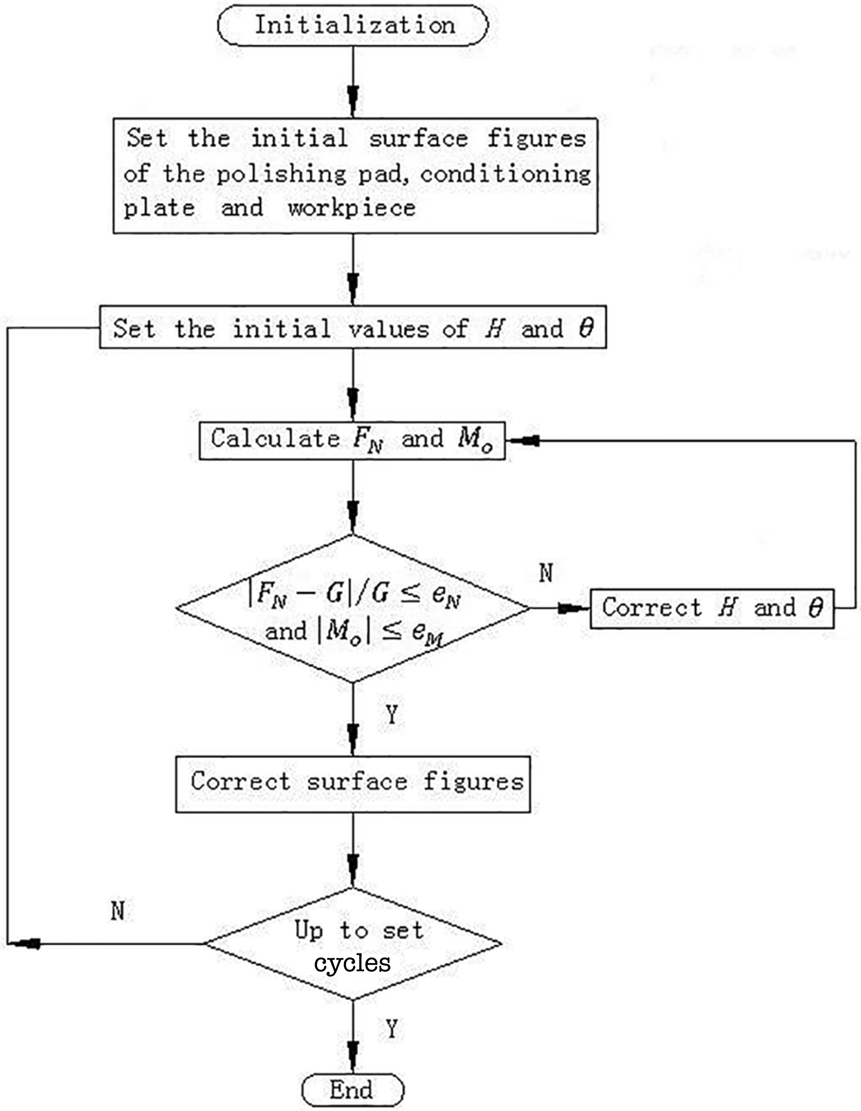
Figure 1. Program flow chart for surface calculation.
The initialization includes every size of the lap, conditioning disk and workpiece, the position and density of the conditioning disk and workpiece, Young’s modulus of the lap, the Preston constants and rotation number, calculation errors, increments for ![]() $H$ and
$H$ and ![]() ${\it\theta}$, and some parameters for integral operation and output file path.
${\it\theta}$, and some parameters for integral operation and output file path.
Setting the initial surface figure refers to setting the profiles along the radial directions of the workpiece, lap and conditioning disk. The profiles can be described as functions or height values at given radial positions in this program.
Table 1. Parameters for calculation and experiments.

The workpiece and conditioning disk have different values of ![]() $H$ and
$H$ and ![]() ${\it\theta}$, but we consider that the computing method for both of them is identical, so
${\it\theta}$, but we consider that the computing method for both of them is identical, so ![]() $H$ and
$H$ and ![]() ${\it\theta}$ refer to both the workpiece and conditioning disk. On the basis of the scanning and variable step method, values of
${\it\theta}$ refer to both the workpiece and conditioning disk. On the basis of the scanning and variable step method, values of ![]() $H$ and
$H$ and ![]() ${\it\theta}$ that satisfy Equation (3) are easily found. For instance, we define an increasing value of
${\it\theta}$ that satisfy Equation (3) are easily found. For instance, we define an increasing value of ![]() $H$ as standing for a decreasing amount of compression for the lap caused by the workpiece and the conditioning disk, with
$H$ as standing for a decreasing amount of compression for the lap caused by the workpiece and the conditioning disk, with ![]() ${\it\theta}$ being positive standing for the outer part of the workpiece and the conditioning disk on the lap surface being lower than the inner part. If the initial given
${\it\theta}$ being positive standing for the outer part of the workpiece and the conditioning disk on the lap surface being lower than the inner part. If the initial given ![]() $H$ and
$H$ and ![]() ${\it\theta}$ result in the total pressure being greater (smaller) than the weight
${\it\theta}$ result in the total pressure being greater (smaller) than the weight ![]() $G$ and the moment for the outer part of the workpiece or the conditioning disk being larger (smaller) than the inner part, then
$G$ and the moment for the outer part of the workpiece or the conditioning disk being larger (smaller) than the inner part, then ![]() $H$ should be increased (reduced) and
$H$ should be increased (reduced) and ![]() ${\it\theta}$ should be reduced (increased) until the comparison reverses, following which
${\it\theta}$ should be reduced (increased) until the comparison reverses, following which ![]() $H$ should be reduced (increased) and
$H$ should be reduced (increased) and ![]() ${\it\theta}$ should be increased (reduced). If every time the comparison reverses, the increment applied to
${\it\theta}$ should be increased (reduced). If every time the comparison reverses, the increment applied to ![]() $H$ or
$H$ or ![]() ${\it\theta}$ is multiplied by a constant smaller than unity, then Equation (3) will soon be true to a given accuracy. The initial values of
${\it\theta}$ is multiplied by a constant smaller than unity, then Equation (3) will soon be true to a given accuracy. The initial values of ![]() $H$,
$H$, ![]() ${\it\theta}$ and the increments are easy to set – for example, setting
${\it\theta}$ and the increments are easy to set – for example, setting ![]() $H$ to the thickness of the lap,
$H$ to the thickness of the lap, ![]() ${\it\theta}$ to zero, the increment for
${\it\theta}$ to zero, the increment for ![]() $H$ to
$H$ to ![]() $10^{-6}~\text{m}$ and the increment for
$10^{-6}~\text{m}$ and the increment for ![]() ${\it\theta}$ to
${\it\theta}$ to ![]() $10^{-6}$ degrees, their values will soon be updated such that Equation (3) is satisfied.
$10^{-6}$ degrees, their values will soon be updated such that Equation (3) is satisfied.
A large number of numerical tests have been performed to verify the accuracy and consistency of the model. For example, it has been found that increasing the Preston constants causes faster changes in the surfaces, and changes in the surface figure from different initial shapes, such as concave, convex, ‘M’-shape and ‘W’-shape, are found to be consistent with experiment.
3. Study of the continuous polishing characteristics
3.1. Basic rules of surface figure adjustment
According to the model, two basic rules are found:
(1) Without moving the conditioning disk, the surface peak–valleys (PVs) of the pitch lap, conditioning disk and workpiece will change at constant speeds after their surfaces completely match.
This rule indicates that an inherent feature of the system is the rate of surface change rather than the specific surface. The rate of change in the workpiece surface PV based on the parameters in Table 1 is given in Figure 2. In the experiments, the material of the lap consists mainly of the Xi’an #66 polishing pitch produced in China with some additives such as beeswax and plastic powder. A square mesh is used in the lap. The squares have edges of 3.0 cm separated by grooves 3 mm in width and 2 mm in depth. A one-percent concentration, water-based CeO2 polishing slurry is added every 5 min, 30 mL a time. The conditioning disk is made of ‘Jinan Green’ stone, sourced from Shandong, China. This is a kind of granite with high stability and low coefficient of thermal expansion. The temperature is controlled at ![]() $22\,^{\circ }\text{C}$ and the relative humidity is 60% in the polishing workshop. The horizontal axis in Figure 2 represents the distance between the center of the conditioning disk and the pitch lap, while the vertical axis represents the change rates, with a change to a convex surface when the axis is positive and a change to concave surface when it is negative. The Preston constants are all set to
$22\,^{\circ }\text{C}$ and the relative humidity is 60% in the polishing workshop. The horizontal axis in Figure 2 represents the distance between the center of the conditioning disk and the pitch lap, while the vertical axis represents the change rates, with a change to a convex surface when the axis is positive and a change to concave surface when it is negative. The Preston constants are all set to ![]() $0.7\times 10^{-12}/\text{Pa}$[Reference Berggren and Schmell6, Reference Tesar and Fuchs7] according to the literature and polishing experience for years. Reference [Reference Berggren and Schmell6] indicates that the Preston constant of conventional polishing for BK7 is approximately
$0.7\times 10^{-12}/\text{Pa}$[Reference Berggren and Schmell6, Reference Tesar and Fuchs7] according to the literature and polishing experience for years. Reference [Reference Berggren and Schmell6] indicates that the Preston constant of conventional polishing for BK7 is approximately ![]() $0.7\times 10^{-12}/\text{Pa}$; the constant should be smaller for the fused silica, which is harder to polish. Reference [Reference Tesar and Fuchs7] shows that the constant for conventional polishing of fused silica is
$0.7\times 10^{-12}/\text{Pa}$; the constant should be smaller for the fused silica, which is harder to polish. Reference [Reference Tesar and Fuchs7] shows that the constant for conventional polishing of fused silica is ![]() $1.0\times 10^{-12}{-}1.2\times 10^{-12}/\text{Pa}$. The value
$1.0\times 10^{-12}{-}1.2\times 10^{-12}/\text{Pa}$. The value ![]() $0.7\times 10^{-12}/\text{Pa}$ may not fit the experiments, but very high accuracy is not necessary because the Preston constant does not influence the surface change rules, which were the main factors to be studied. The wear rate of the conditioning disk and the pitch lap are of the same order as the fused silica according to experience, so all the constants are set to
$0.7\times 10^{-12}/\text{Pa}$ may not fit the experiments, but very high accuracy is not necessary because the Preston constant does not influence the surface change rules, which were the main factors to be studied. The wear rate of the conditioning disk and the pitch lap are of the same order as the fused silica according to experience, so all the constants are set to ![]() $0.7\times 10^{-12}/\text{Pa}$. The rotation speed is two revolutions per minute.
$0.7\times 10^{-12}/\text{Pa}$. The rotation speed is two revolutions per minute.
Some differences are found between the calculated and experimental results because the Preston equation is not completely satisfied, as a result of the nonlinear characteristic of the pitch lap. Errors exist in the experiments and calculation because of interference and inaccurate setting of the Preston constants. However, the basic rules shown by the model are accurate because the shapes of the two curves are similar.
(2) An equilibrium state exists in the system, indicating that the surface shape could remain unchanged, and the shape could be flat or spherical with a small curvature.
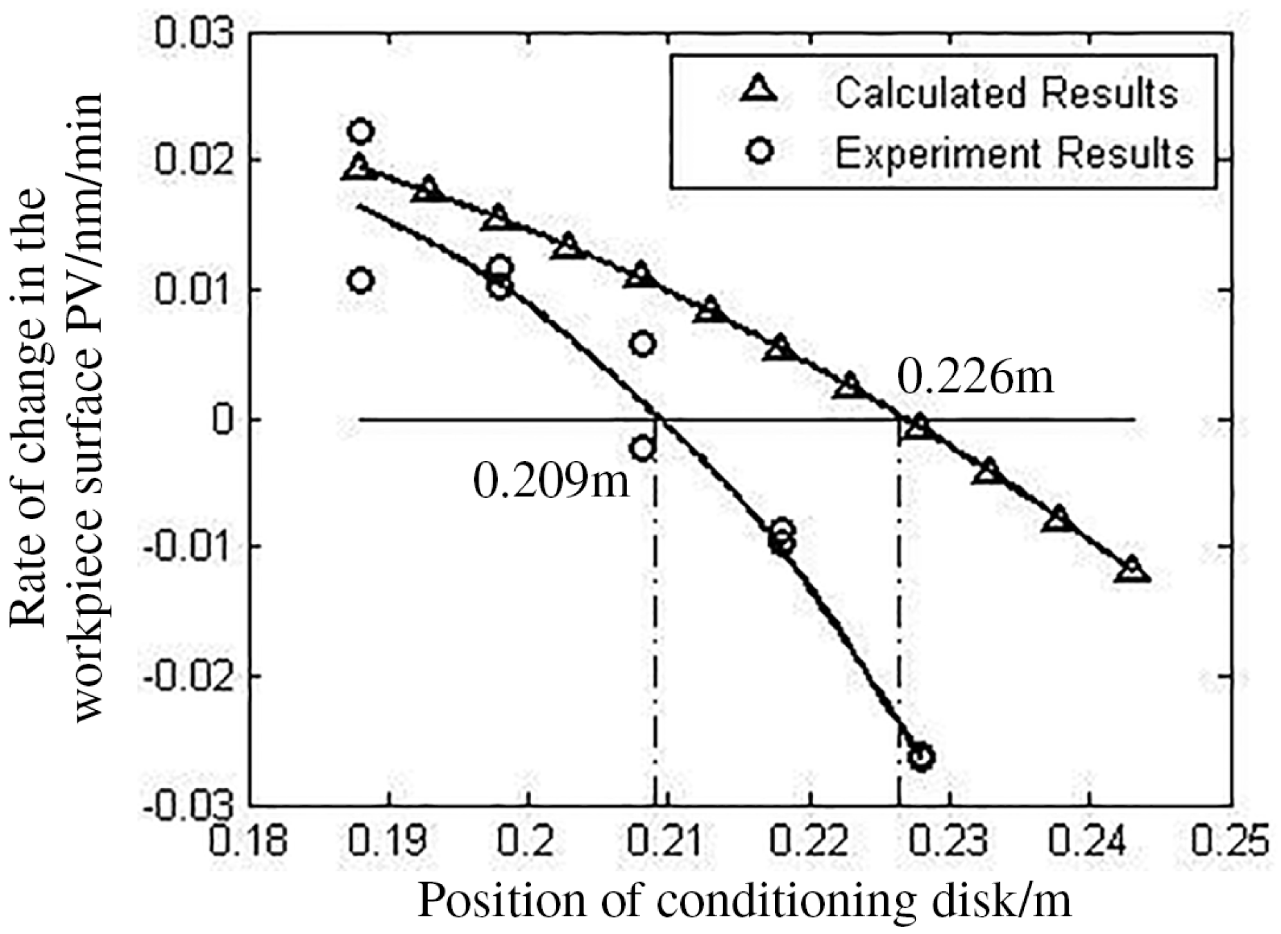
Figure 2. Rate of change in the workpiece surface PV.

Figure 3. Maintained workpiece surface shape experiment.

Figure 4. Lap surface damaged by the workpiece.
The conditioning disk position corresponding to the equilibrium state is the equilibrium position marked in Figure 2. The difference between the calculated and experimental result is 17 mm, and error is inevitable. Results for the surface maintained during the experiment are given in Figure 3, in which the fluctuation is caused by an unstable environment. The following analysis indicates that a polishing workpiece in equilibrium is the ideal work state of a continuous polishing machine. This characteristic lays the theoretical foundations for high-efficiency and high-precision polishing.
3.2. Workpiece polishing in the equilibrium state
Different radial positions of the pitch lap have different friction distances from the workpiece. Thus, the lap deteriorates regardless of the shape of the workpiece surface, even though it may be an ideal plane. Figure 4 is a simulation of workpiece polishing without a conditioning disk according to the model. The initial shapes of the lap surface and the workpiece are both ideal planes. This figure is a sectional view of the lap, in which the fine lines stand for its worn shape and the dot-dash lines on the left side stand for the shape of the workpiece surface. The condition after 1st, 11th, 21st, 31st and 41st cycles are presented. The damage caused by a workpiece without surface error is illustrated. The damage to the lap surface contains two parts; one is the groove at the annulus center caused by the finite workpiece dimensions, called partial damage, and the other is departure of the bottom of the groove from the flat surface, called general damage.
If a conditioning disk is applied, the partial damage can be repaired naturally. Thus, the main task is to repair the general damage, which is most important in determining the workpiece surface figure. The workpiece surface can remain high-precision under equilibrium in flat cases, according to the above analysis. Further calculations show that the equilibrium state is insensitive to the surface error of the workpiece. If equilibrium with flat surfaces is obtained, exchanging the workpiece with another workpiece with surface error can also allow polishing to very high accuracy without moving the conditioning disk. This phenomenon indicates that in the process the curvature change is very small between the case of a mismatching workpiece and pitch lap and the perfectly matched case in the equilibrium state. These results can lead to a theoretical basis for high-efficiency and high-precision polishing. Figure 5 is the result of successive changes in workpieces according to the model. In the simulation, the system is first adjusted to the equilibrium state with flat surfaces, with the surface PV of the workpiece being approximately 1 nm. Then, the workpiece is replaced by other workpieces of the same material and size but with a concave surface with an error of 632.8 nm. Furthermore, a fresh workpiece is replaced each time the workpiece surface becomes stable. The process is repeated 20 times. The surface error of the final workpiece is found to be 8 nm, and the shape is concave. The parameters of the conditioner and pitch lap for the calculation are given in Table 1. The workpiece size is ![]() $\emptyset 20\times 30~\text{mm}$ with a density of
$\emptyset 20\times 30~\text{mm}$ with a density of ![]() $2500\;\text{kg}/\text{m}^{3}$. All Preston constants are set to
$2500\;\text{kg}/\text{m}^{3}$. All Preston constants are set to ![]() $0.7\times 10^{-12}/\text{Pa}$. When the concave workpieces are replaced with convex ones, the surfaces are still highly accurate.
$0.7\times 10^{-12}/\text{Pa}$. When the concave workpieces are replaced with convex ones, the surfaces are still highly accurate.
Thus, analytical results show that polishing workpieces at equilibrium is efficient and highly precise. To obtain and maintain the equilibrium state, the following steps should be performed:
(1) the equilibrium position should be explored;
(2) an appropriate method to adjust the shape of the lap surface should be applied; and
(3) the conditioning disk position should be adjusted according to the polishing condition.
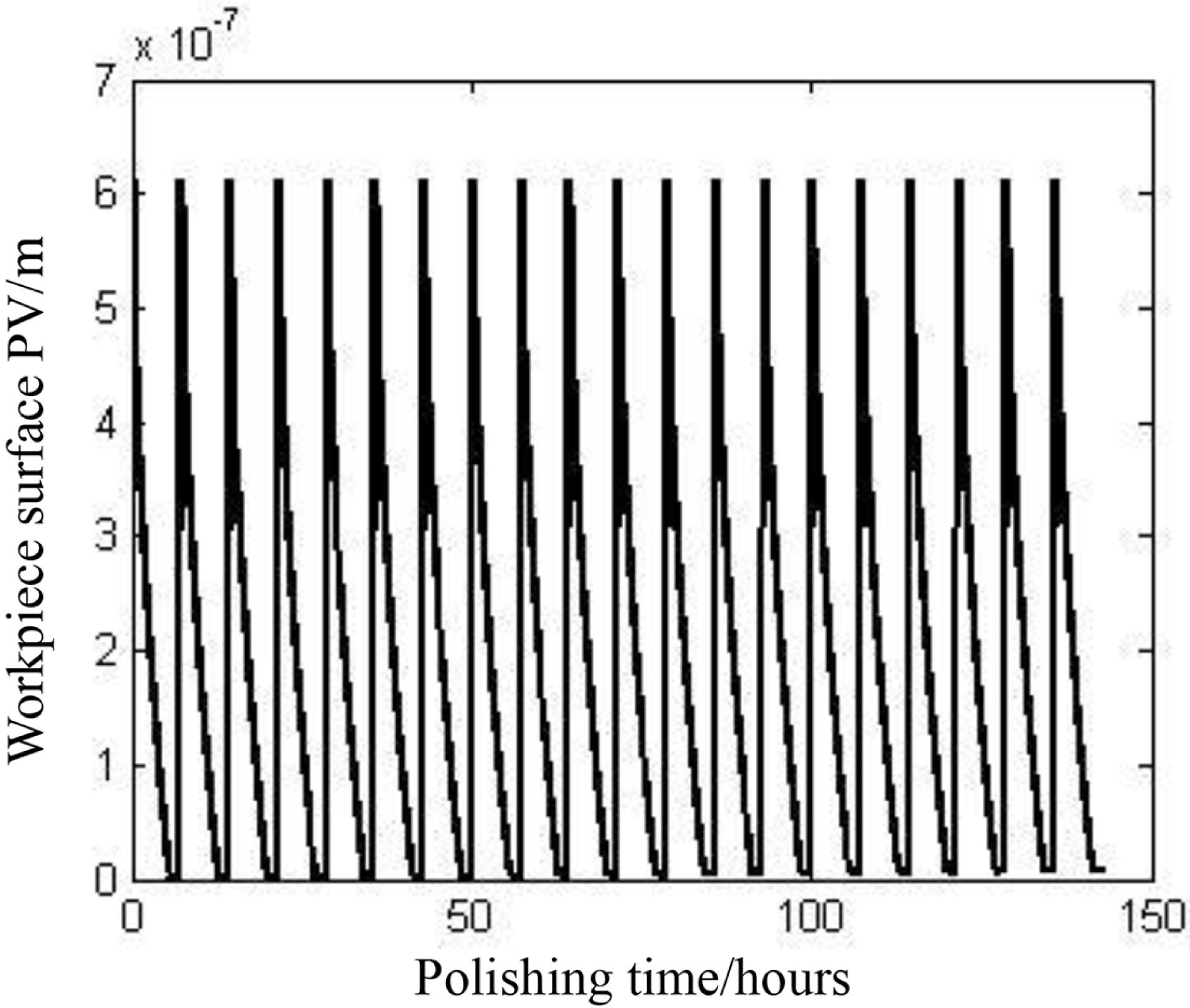
Figure 5. Change in the workpiece surface.
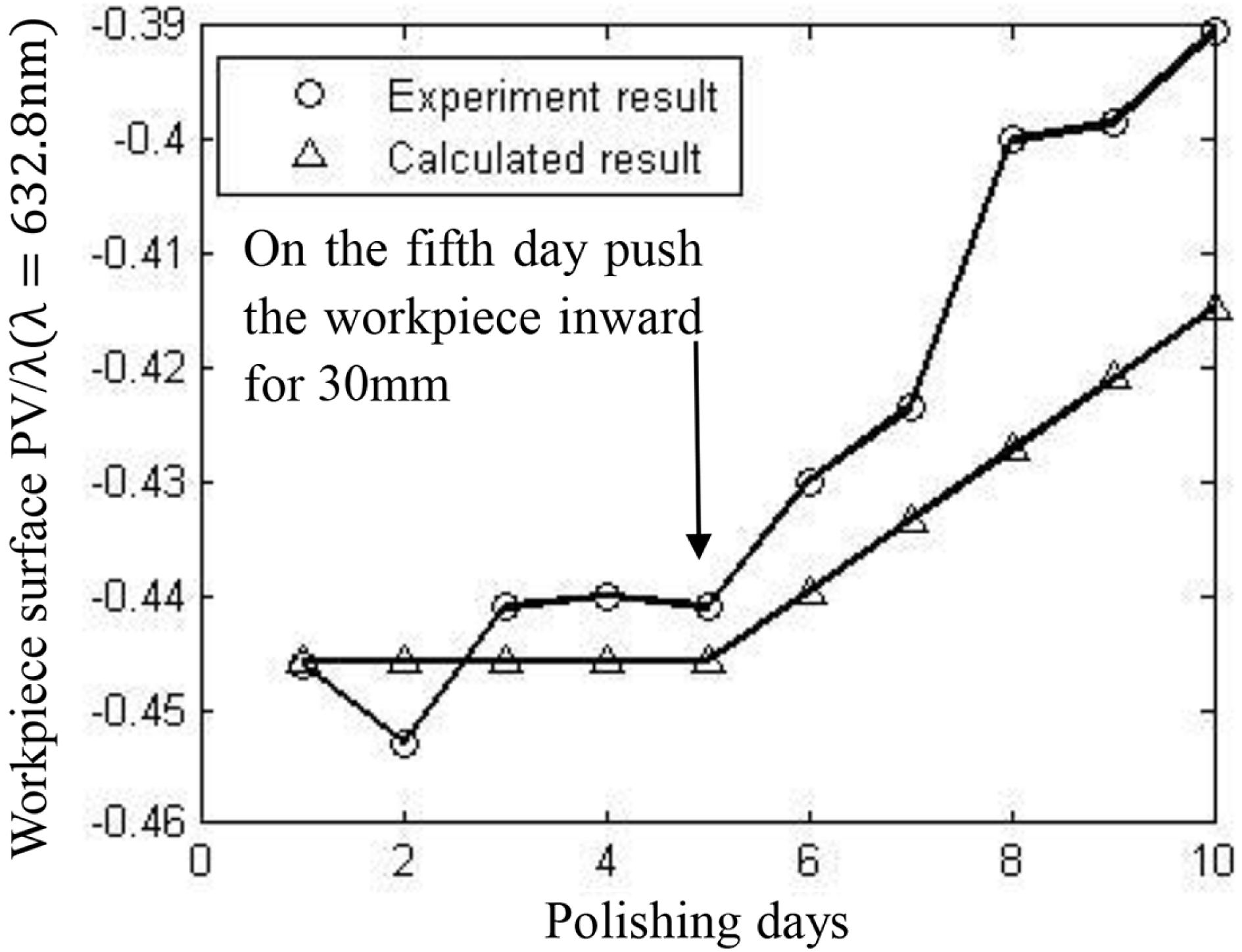
Figure 6. Change in the workpiece surface caused by motion in the radial direction of the lap.
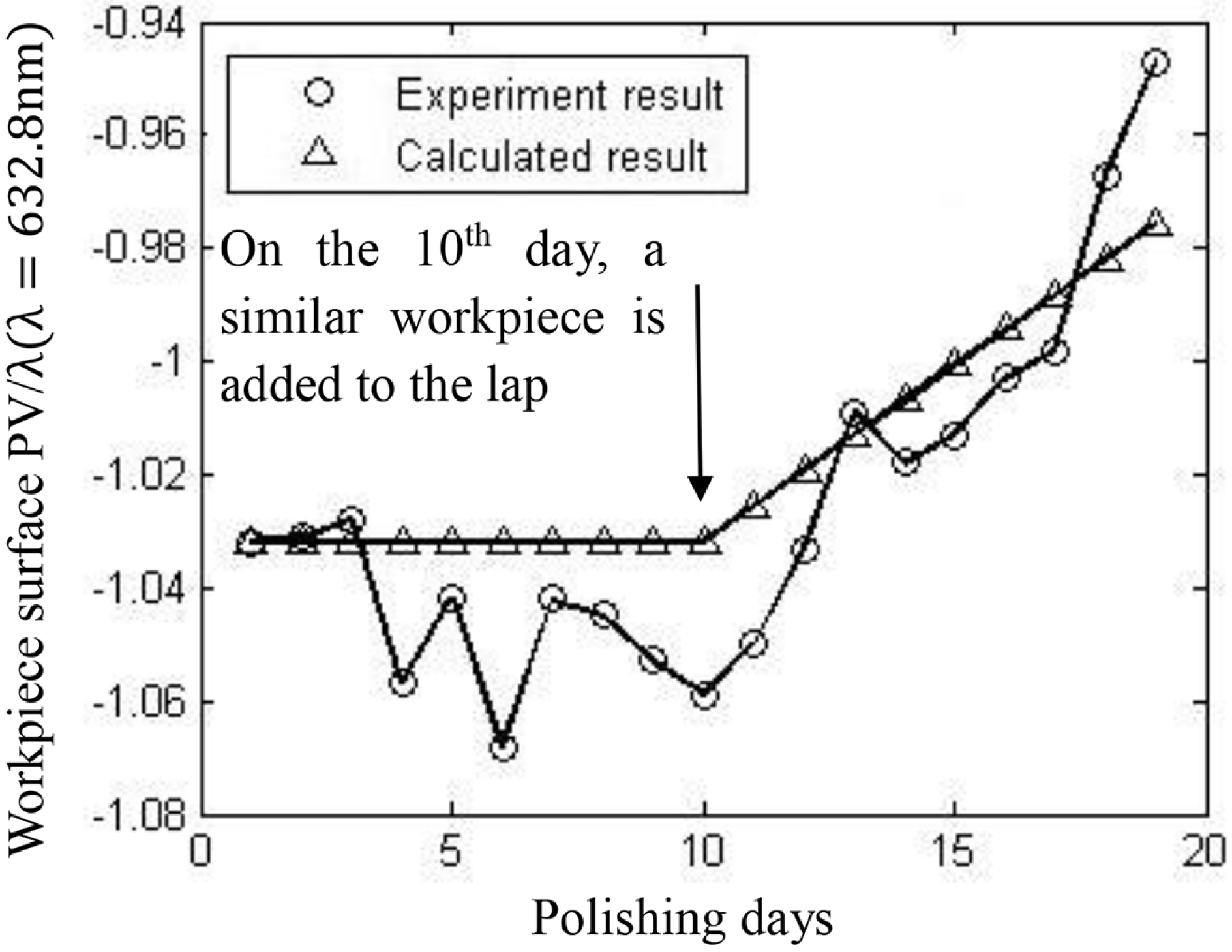
Figure 7. Change in the workpiece surface caused by a change in quantity.
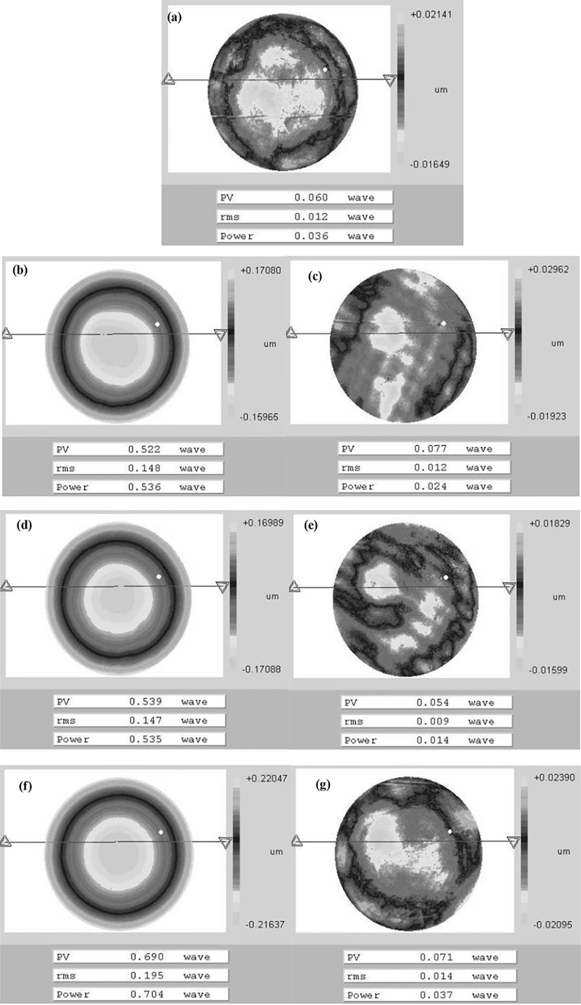
Figure 8. Workpieces continously polished in an equilibrium state.
The equilibrium state can be found by measuring the rates of change of the workpiece surface under different conditioner positions (Figure 2). The equilibrium position is usually in the middle ![]() $1/3$rd of the annulus; hence, experiments could be performed in this range. The equilibrium position is actually not fixed, even in a certain machine, and the machining parameters remain unchanged. The position will change according to the workpiece parameters, such as the workpiece position, size, quantity, pressures applied, and so on. Thus, the experiments should depend on the workpieces to be polished. Simulation results show that if the workpiece is placed at the center of the lap annulus, the extent of worn area in the inner side of the annulus is larger than that at the outer side. If the size, or the quantity, or the applied pressure of the workpiece is larger, the conditioning disk should be pushed outwards to maintain balance. If the workpiece is moved along the radial direction of the lap, the conditioning disk should be pushed towards the opposite side to maintain balance. Figure 6 shows that the surface changes to convex when the workpiece is pushed inwards, the original workpiece position is at the center of the annulus. The parameters are listed in Table 1. The workpiece material is fused silica. A single Preston constant is applied for all calculations, that is,
$1/3$rd of the annulus; hence, experiments could be performed in this range. The equilibrium position is actually not fixed, even in a certain machine, and the machining parameters remain unchanged. The position will change according to the workpiece parameters, such as the workpiece position, size, quantity, pressures applied, and so on. Thus, the experiments should depend on the workpieces to be polished. Simulation results show that if the workpiece is placed at the center of the lap annulus, the extent of worn area in the inner side of the annulus is larger than that at the outer side. If the size, or the quantity, or the applied pressure of the workpiece is larger, the conditioning disk should be pushed outwards to maintain balance. If the workpiece is moved along the radial direction of the lap, the conditioning disk should be pushed towards the opposite side to maintain balance. Figure 6 shows that the surface changes to convex when the workpiece is pushed inwards, the original workpiece position is at the center of the annulus. The parameters are listed in Table 1. The workpiece material is fused silica. A single Preston constant is applied for all calculations, that is, ![]() $0.7\times 10^{-12}/\text{Pa}$. Figure 7 demonstrates the changes in the workpiece surface caused by a change in the quantity. On the 10th day, a workpiece with the same material, size and surface figure is added to the other workstation on the pitch lap, and surface development into a convex shape is observed. The relationship between each change condition of the workpiece and the equilibrium position can be described mathematically, as will be discussed in future articles.
$0.7\times 10^{-12}/\text{Pa}$. Figure 7 demonstrates the changes in the workpiece surface caused by a change in the quantity. On the 10th day, a workpiece with the same material, size and surface figure is added to the other workstation on the pitch lap, and surface development into a convex shape is observed. The relationship between each change condition of the workpiece and the equilibrium position can be described mathematically, as will be discussed in future articles.
Given the delayed response of the pitch lap, measurement results beyond the equilibrium state cannot represent the true surface shape, which makes the lap surface difficult to control accurately. The model shows a delayed response in which the surface does not stop changing immediately after the conditioning disk is pushed to the equilibrium position. To adjust the lap surface, the shape of the workpiece surface should be measured in the equilibrium state. Then, from the surface error and the change rates measured, the distance of movement for the conditioner and the conditioning time is determined. At the end of this calculated time, the conditioner is pushed back to the equilibrium position, and the surface figure is again checked when it is stable. If an error still exists, it may have been caused by an environmental disturbance or calculation errors. The disturbance and errors are eliminated, and the lap is reconditioned.
The key to stable machining is maintenance of the pitch lap surface. From the analyses above, a lap in the equilibrium state is insensitive to the surface error of the workpiece. However, when the position or size of the workpiece changes without moving the conditioning disk, the equilibrium state disappears, and the lap surface will deteriorate. Thus, the conditioner position should be adjusted according to the workpiece to prolong the ideal state.
Figure 8 shows experimental results with the system parameters in Table 1. The workpiece material is fused silica. The shape of lap surface is adjusted in a similar way to the steps mentioned above. The equilibrium position is found after the change rate curve of the workpiece surface is measured, and the adjustment is in good numerical agreement with the measured rates. Figure 8(a) is the shape of the monitored workpiece surface after the adjustment process, at which point the workpieces are changed in succession. Figures 8(b), 8(d) and 8(f) are the workpieces before polishing. The workpieces have concave surfaces, and the testing wavelength is 632.8 nm. Figures 8(c), 8(e) and 8(g) are surface figures after polishing for 8 h without detection. The results clearly indicate the advantages of high efficiency and high accuracy when polishing at equilibrium. As a further test, a convex workpiece is polished. The convex workpiece always floats on the lap, because of hydromechanical effects[Reference Scoff, Runnels and Eyman8–Reference Terrell and Fred Higgs10], and the material removal rate is very low, so the edge of the workpiece is not polished after 8 h. When polishing concave workpieces the friction force is very large, which leads to a high polishing speed. Thus, the workpiece should be concave before polishing on a continuous machine.
4. Conclusion and discussion
An ideal mathematical model for a continuous polishing system is built. According to the model, the mechanism of surface changes in the system is examined, and the equilibrium state, which indicates that the surfaces remain unchanged, is found in the polishing system. The model shows that although the surface of the workpiece is an ideal plane, it will also damage the lap. Therefore, the damage caused by workpieces with surface errors may not be that serious – and this phenomenon has been proved theoretically. The change in curvature is very small between the case of workpiece–lap mismatch to that of a perfect match in the equilibrium state. This characteristic lays the theoretical foundations for high-efficiency and high-precision polishing. The procedures for obtaining an ideal equilibrium state are performed and verified experimentally.
Calculations show that the polishing process is actually deterministic, and the shapes of the workpiece surfaces can be precisely controlled. An unstable environment (such as fluctuations in temperature and humidity, and irregular airflows) and imperfect factors in polishing (such as the nonuniform temperature distribution of the lap and the workpieces, uneven polishing powders on the surface of the lap, unstable rotating speeds of the workpieces, and so on) will seriously impact the machining precision and make the polishing a nondeterministic process. However, with technological developments, such as a higher control accuracy of the environment temperature and humidity, enhanced performance of polishing machines, studies on the polishing materials and material removal mechanisms, as well as the application of computer simulations in conventional polishing, conventional polishing will become a deterministic process.
Acknowledgements
The study is supported by grants from the Chinese and Israeli Cooperation Project on High-power Laser Technology (2010DFB70490).


