1 Introduction
Optical parametric chirped-pulse amplification (OPCPA) has been a popular technique to amplify a broadband optical pulse in recent years[Reference Danson, Hillier, Hopps and Neely1, Reference Rothhardt, Hädrich, Delagnes, Cormier and Limpert2]. This is mainly due to some important advantages of OPCPA. Most notably, for different wavelengths, from visible to infrared, OPCPA can support wide gain bandwidth by choosing appropriate nonlinear crystals and satisfying its phase-matching conditions. Meanwhile, OPCPA provides a high gain in a relatively short path length, which can minimize the B-integral and reduce spatial aberration caused by thermal loading effects[Reference Ross, Matousek, Towrie, Langley and Collier3, Reference Riedel, Rothhardt, Beil, Gronloh, Klenke, Hoppner, Schulz, Teubner, Krankel, Limpert, Tunnermann, J. Prandolini and X. Kärtner4]. In the front-end parts of large high-intensity ultrashort pulse laser systems, many prominent works have been done with OPCPA. Picosecond or even femtosecond pumped OPCPA can deliver a sufficiently broad spectrum and greatly improve the pulse contrast[Reference Fülöp, Major, Henig, Kruber, Weingartner, Clausnitzer, Kley, Tünnermann, Pervak, Apolonski, Osterhoff, Hörlein, Krausz and Karsch5–Reference Novák, Turčičová, Divoký, Smrž, Huynh and Straka8]. Diode pumped laser or thin disk laser pumped OPCPA has been successfully demonstrated at a variety of repetition rates[Reference Su, Peng, Chen, Li, Wang and Leng9–Reference Budriūnas, Stanislauskas, Adamonis, Aleknavičius, Veitas, Gadonas, Balickas, Michailovas and Varanavičius11].
Before the main amplifier of a petawatt level laser, a pre-amplifier is required to provide signal pulses of tens to hundreds millijoules of energy. Many articles have reported OPCPA amplifier at different wavelengths based on different crystals, and the output energy is from millijoules to sub-joule level[Reference Zeng, Zhou, Zuo, Zhu, Su, Wang, Wang, Huang, Jiang, Jiang, Guo, Xie, Zhou, Wu, Mu, Peng and Jing12–Reference Liao, Jovanovic, Ebbers, Fei and Chai14]. Maximizing the pulse energy from a broadband pre-amplifier reduces the total gain narrowing in the system and yields the shortest available transform-limited compressed pulses. Carefully designed signal and pump spatial–temporal profiles and the properly set ratio of pump and seed pulse durations are naturally beneficial to the conversion efficiency and bandwidth and simultaneously suppress the super-fluorescence[Reference Moses, Manzoni, Huang, Cerullo and Kartner15, Reference Bagnoud, Begishev, Guardalben, Puth and Zuegel16]. However, the conversion efficiency cannot easily increase to over 40% in the traditional OPCPA amplifier of one crystal scheme. The gain bandwidth narrowing and back conversion effect caused by phase mismatching of the pump and signal are the crucial obstacle to improve conversion efficiency further. To inhibit these effects, Ma et al. used a
![]() $\text{Sm}^{3+}$
-doped yttrium calcium oxyborate crystal that is highly absorptive at the idler wavelength and transparent at the pump and signal wavelengths, making an experimental OPCPA conversion efficiency of 41%[Reference Ma, Wang, Yuan, Xie, Xiong, Tu, Tu, Shi, Zheng and Qian17]. In their OPCPA configuration, the nonlinear crystal must be quite long enough to provide enough signal gain which can lead to spatial gain narrowing and affect the signal output energy efficiency and stability. Another recent work proposed cascaded extraction optical parametric amplification (OPA) for the design of high efficiency final amplifier and their numerical simulation showed a highest efficiency of 50%[Reference Cao, Tóth, Yamanaka, Kalashnikov, Chvykov and Osvay18].
$\text{Sm}^{3+}$
-doped yttrium calcium oxyborate crystal that is highly absorptive at the idler wavelength and transparent at the pump and signal wavelengths, making an experimental OPCPA conversion efficiency of 41%[Reference Ma, Wang, Yuan, Xie, Xiong, Tu, Tu, Shi, Zheng and Qian17]. In their OPCPA configuration, the nonlinear crystal must be quite long enough to provide enough signal gain which can lead to spatial gain narrowing and affect the signal output energy efficiency and stability. Another recent work proposed cascaded extraction optical parametric amplification (OPA) for the design of high efficiency final amplifier and their numerical simulation showed a highest efficiency of 50%[Reference Cao, Tóth, Yamanaka, Kalashnikov, Chvykov and Osvay18].
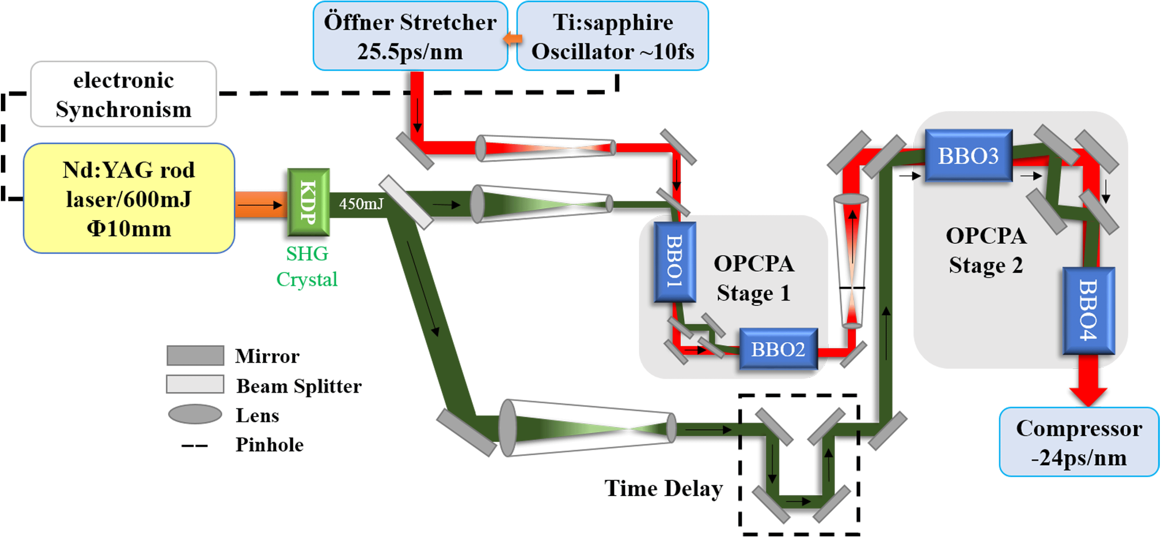
Figure 1. OPCPA pre-amplifier schematic and laser path diagram.
In this paper, we designed, theoretically simulated and experimentally demonstrated a high conversion efficiency broadband OPCPA system based on BBO crystals, which will be used as the optimized pre-amplifier for Shen Guang-II 5PW (SG-II 5PW) facility at National Laboratory on High Power Laser and Physics (NLHPLP, SIOM, CAS)[Reference Zhu, Xie, Sun, Kang, Yang, Guo, Zhu, Zhu, Gao, Liang, Cui, Yang, Zhang and Lin19]. To output higher signal pulse energy, maximize the pump-to-signal conversion efficiency while ensuring gain broadband, our general idea is to incorporate the concept of eliminating idler from the specific design of pre-amplifier structure and OPCPA configurations. In this pre-amplifier structure, there are two traditional configuration OPCPA stages, and each amplification stage consists of two BBO crystals. Meanwhile, the effect of pump-to-signal spatial walk-off, which is related to beam quality and energy stability, is discussed and compensated in our designed OPCPA configuration.
2 OPCPA pre-amplifier design
The current requirement for the pre-amplifier of SG-II 5PW facility is to improve the conversion efficiency while broadening the spectrum bandwidth to support the compressed pulse duration under 30 fs. The pump pulse for OPCPA pre-amplifier is an existing Nd:YAG rod laser used in SG-II 5PW pre-amplifier, which provides hundreds of millijoules energy at second harmonics generation. Our design objective is to extract energy from the pump as much as possible while enlarging spectrum bandwidth and minimizing beam spatial distortion caused by birefringent walk-off.
The overall structure of the OPCPA pre-amplifier ordered front to back is oscillator, stretcher, OPCPA stage 1 and OPCPA stage 2. The designed pre-amplifier schematic and laser path diagram that the following analyses and numerical simulation are in relation to are given in Figure 1. The signal seed comes from a mode-locked Ti:sapphire oscillator which provides
![]() ${\sim}2~\text{nJ}$
pulses at 808 nm. The pulse duration is 10 fs and full width at half maximum (FWHM) spectrum bandwidth is about 100 nm. Then the signal is stretched in an Öffner stretcher, after which the chirped signal pulse width is 2.55 ns with the chirp ratio
${\sim}2~\text{nJ}$
pulses at 808 nm. The pulse duration is 10 fs and full width at half maximum (FWHM) spectrum bandwidth is about 100 nm. Then the signal is stretched in an Öffner stretcher, after which the chirped signal pulse width is 2.55 ns with the chirp ratio
![]() $25.5~\text{ps}/\text{nm}$
and spectrum bandwidth of
$25.5~\text{ps}/\text{nm}$
and spectrum bandwidth of
![]() ${\sim}100~\text{nm}$
. The signal energy per pulse becomes approximately 0.2 nJ after the stretcher. The pump laser provides total 450 mJ energy per pulse in 2.2 ns pulse width for the next two OPCPA stages. Pump pulse energy would be split into OPCPA stage 1 and stage 2 by the beam splitter. The repetition rate of OPCPA system is 1 Hz which is determined by the pump laser.
${\sim}100~\text{nm}$
. The signal energy per pulse becomes approximately 0.2 nJ after the stretcher. The pump laser provides total 450 mJ energy per pulse in 2.2 ns pulse width for the next two OPCPA stages. Pump pulse energy would be split into OPCPA stage 1 and stage 2 by the beam splitter. The repetition rate of OPCPA system is 1 Hz which is determined by the pump laser.
A special design for the OPA configuration is that there are two crystals in one OPA stage, where the two BBO crystals are not cascade. The idler is separated after amplified in the former BBO, and only pump and signal are delivered to the other BBO crystal. The specific two crystal configuration is presented in Figure 2, and we named it ‘L’ type configuration. In our opinion, this is a relatively simple way to dissipate the idler although it does not directly affect the OPCPA process as the method of depleting idler by material loss used in Ref. [Reference Ma, Wang, Yuan, Xie, Xiong, Tu, Tu, Shi, Zheng and Qian17]. However, as will be discussed in the numerical simulation, its effect on the OPCPA will be significant while the crystal length is specially designed. Additionally, BBO crystal has the well-known large walk-off angle. To compensate the walk-off effect, the extraordinary axes of two BBO crystals in one stage are oriented in opposing directions, leading to the opposing pump-to-signal walk-off directions in two crystals. All the BBO crystals are configured for type-I phase matching. The phase-matching angle and the non-collinear angle for 808 nm centered broadband gain are set to
![]() $23.84^{\circ }$
and
$23.84^{\circ }$
and
![]() $2.37^{\circ }$
, respectively.
$2.37^{\circ }$
, respectively.
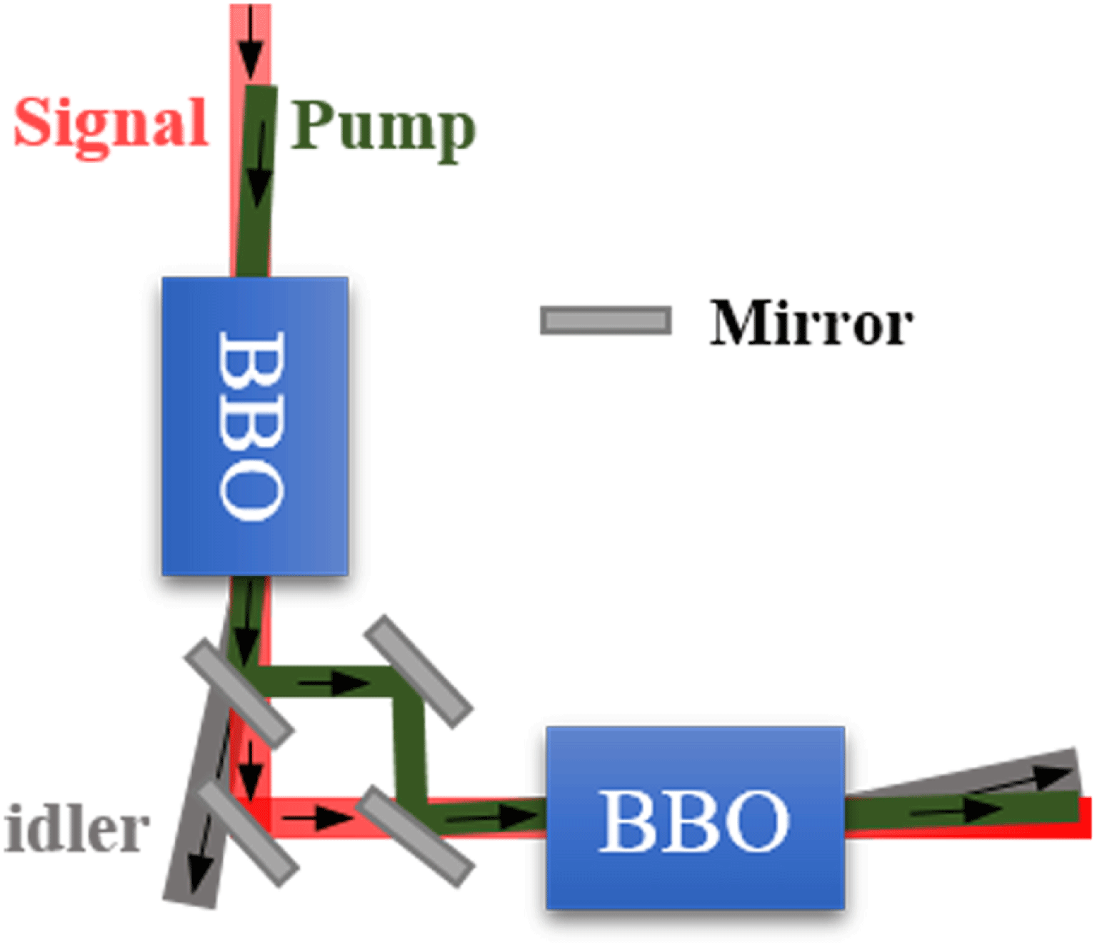
Figure 2. Two BBO crystals OPCPA in ‘L’ type configuration.
2.1 Numerical model
Before an experimental confirmation of our OPCPA design, theoretical analysis and parameter optimization are carried out first. The OPCPA process is numerically simulated by using the slowly varying envelope approximation nonlinear coupled wave equations[Reference Andrianov, Szabo, Sergeev, Kim, Chvykov and Kalashnikov20],
 $$\begin{eqnarray}\displaystyle \begin{array}{@{}rcl@{}} & & \unicode[STIX]{x1D6FB}_{\bot }^{2}E_{s}+j{\displaystyle \frac{2n_{s}\unicode[STIX]{x1D714}_{s}}{c}}\left({\displaystyle \frac{\unicode[STIX]{x2202}E_{s}}{\unicode[STIX]{x2202}z}}-\unicode[STIX]{x1D70C}_{s}{\displaystyle \frac{\unicode[STIX]{x2202}E_{s}}{\unicode[STIX]{x2202}y}}\right)\\ & & \quad =-{\displaystyle \frac{2\unicode[STIX]{x1D714}_{s}^{2}d_{\text{eff}}}{c^{2}}}E_{i}^{\ast }E_{p}\exp (-j\unicode[STIX]{x0394}kz),\\ \\ & & \unicode[STIX]{x1D6FB}_{\bot }^{2}E_{i}+j{\displaystyle \frac{2n_{i}\unicode[STIX]{x1D714}_{i}}{c}}\left({\displaystyle \frac{\unicode[STIX]{x2202}E_{i}}{\unicode[STIX]{x2202}z}}-\unicode[STIX]{x1D70C}_{i}{\displaystyle \frac{\unicode[STIX]{x2202}E_{i}}{\unicode[STIX]{x2202}y}}\right)\\ & & \quad =-{\displaystyle \frac{2\unicode[STIX]{x1D714}_{i}^{2}d_{\text{eff}}}{c^{2}}}E_{s}^{\ast }E_{p}\exp (-j\unicode[STIX]{x0394}kz),\\ \\ & & \unicode[STIX]{x1D6FB}_{\bot }^{2}E_{p}+j{\displaystyle \frac{2n_{p}\unicode[STIX]{x1D714}_{p}}{c}}\left({\displaystyle \frac{\unicode[STIX]{x2202}E_{p}}{\unicode[STIX]{x2202}z}}-\unicode[STIX]{x1D70C}_{p}{\displaystyle \frac{\unicode[STIX]{x2202}E_{p}}{\unicode[STIX]{x2202}y}}\right)\\ & & \quad =-{\displaystyle \frac{2\unicode[STIX]{x1D714}_{p}^{2}d_{\text{eff}}}{c^{2}}}E_{s}E_{i}\exp (j\unicode[STIX]{x0394}kz),\end{array} & & \displaystyle\end{eqnarray}$$
where subscripts
![]() $s$
,
$s$
,
![]() $i$
, and
$i$
, and
![]() $p$
refer to the signal, idler, and pump waves, respectively. The transverse Laplacian operator (
$p$
refer to the signal, idler, and pump waves, respectively. The transverse Laplacian operator (
![]() $\unicode[STIX]{x1D6FB}_{\bot }^{2}=\unicode[STIX]{x2202}^{2}/\unicode[STIX]{x2202}x^{2}+\unicode[STIX]{x2202}^{2}/\unicode[STIX]{x2202}y^{2}$
) describes the beam diffraction while propagating along the
$\unicode[STIX]{x1D6FB}_{\bot }^{2}=\unicode[STIX]{x2202}^{2}/\unicode[STIX]{x2202}x^{2}+\unicode[STIX]{x2202}^{2}/\unicode[STIX]{x2202}y^{2}$
) describes the beam diffraction while propagating along the
![]() $z$
-axis.
$z$
-axis.
![]() $E$
is the pulse complex field amplitude, and the energy flux for each wave is proportional to
$E$
is the pulse complex field amplitude, and the energy flux for each wave is proportional to
![]() $|E|^{2}$
; the letter
$|E|^{2}$
; the letter
![]() $n$
is the index of refraction and
$n$
is the index of refraction and
![]() $\unicode[STIX]{x1D714}$
is the angular frequency of electric field;
$\unicode[STIX]{x1D714}$
is the angular frequency of electric field;
![]() $d_{\text{eff}}$
represents the effective nonlinear coefficient for type-I parametric interaction, and parameters
$d_{\text{eff}}$
represents the effective nonlinear coefficient for type-I parametric interaction, and parameters
![]() $c$
,
$c$
,
![]() $z$
are the light speed and propagation distance, respectively. The birefringence walk-off angle of the pump is given by
$z$
are the light speed and propagation distance, respectively. The birefringence walk-off angle of the pump is given by
![]() $\unicode[STIX]{x1D70C}_{p}$
, and the angle between the signal (idler) Poynting vector and the pump wave vector is accounted for
$\unicode[STIX]{x1D70C}_{p}$
, and the angle between the signal (idler) Poynting vector and the pump wave vector is accounted for
![]() $\unicode[STIX]{x1D70C}_{s}$
(
$\unicode[STIX]{x1D70C}_{s}$
(
![]() $\unicode[STIX]{x1D70C}_{i}$
). Since OPCPA follows the conservation of energy and momentum, the wave vector mismatch
$\unicode[STIX]{x1D70C}_{i}$
). Since OPCPA follows the conservation of energy and momentum, the wave vector mismatch
![]() $\unicode[STIX]{x0394}k$
satisfies the formula,
$\unicode[STIX]{x0394}k$
satisfies the formula,
![]() $\unicode[STIX]{x0394}k=k_{p}-k_{s}-k_{i}$
. A fourth-order Runge–Kutta split-step Fourier (SSF) numerical method is used to solve Equation (1) in time domain, and the free-propagation components were obtained by adopting the SSF method.
$\unicode[STIX]{x0394}k=k_{p}-k_{s}-k_{i}$
. A fourth-order Runge–Kutta split-step Fourier (SSF) numerical method is used to solve Equation (1) in time domain, and the free-propagation components were obtained by adopting the SSF method.
In the simulation, the intensities of the signal and pump are assumed to take the following Equations (2) and (3),
 $$\begin{eqnarray}\displaystyle I_{p} & = & \displaystyle I_{0p}\exp \left[-\left(\frac{x^{2}+y^{2}}{\unicode[STIX]{x1D711}_{p}^{2}}\right)^{6}\right]\exp \left[-\left(\frac{t^{2}}{\unicode[STIX]{x1D70F}_{p}^{2}}\right)^{4}\right].\end{eqnarray}$$
The spatial and temporal profiles of the signal pulse are super Gaussian and Gaussian which is closest to the chirped signal seed used in SG-II 5PW, while the pump profiles are both super Gaussian. The signs
![]() $\unicode[STIX]{x1D711}_{s}$
,
$\unicode[STIX]{x1D711}_{s}$
,
![]() $\unicode[STIX]{x1D711}_{p}$
,
$\unicode[STIX]{x1D711}_{p}$
,
![]() $\unicode[STIX]{x1D70F}_{s}$
, and
$\unicode[STIX]{x1D70F}_{s}$
, and
![]() $\unicode[STIX]{x1D70F}_{p}$
are the beam aperture size and time width for signal and pump pulse at
$\unicode[STIX]{x1D70F}_{p}$
are the beam aperture size and time width for signal and pump pulse at
![]() $1/e$
peak intensity. In practice, the beam aperture
$1/e$
peak intensity. In practice, the beam aperture
![]() $\unicode[STIX]{x1D6F7}$
as well as the time width
$\unicode[STIX]{x1D6F7}$
as well as the time width
![]() $T$
are defined as the FWHM, and their relationship is
$T$
are defined as the FWHM, and their relationship is
![]() $\unicode[STIX]{x1D711}=2(\ln 2)^{1/m}\unicode[STIX]{x1D6F7}$
and
$\unicode[STIX]{x1D711}=2(\ln 2)^{1/m}\unicode[STIX]{x1D6F7}$
and
![]() $\unicode[STIX]{x1D70F}=2(\ln 2)^{1/m}T$
, where the symbol
$\unicode[STIX]{x1D70F}=2(\ln 2)^{1/m}T$
, where the symbol
![]() $m$
is the super Gaussian order. As corresponded to the OPCPA structure designed above and our existing pump and chirped signal pulse, the initial signal beam aperture at FWHM is 5 mm, and the pump beam apertures at FWHM for OPCPA stages 1 and 2 are 4 mm and 8.5 mm, respectively. Their initial time widths at FWHM have been described in the pre-amplifier design.
$m$
is the super Gaussian order. As corresponded to the OPCPA structure designed above and our existing pump and chirped signal pulse, the initial signal beam aperture at FWHM is 5 mm, and the pump beam apertures at FWHM for OPCPA stages 1 and 2 are 4 mm and 8.5 mm, respectively. Their initial time widths at FWHM have been described in the pre-amplifier design.
2.2 Numerical simulation results
OPCPA stage 1 is in the high gain region of the amplifier, and the gain obeys the small signal gain formula described in Ref. [Reference Moses, Manzoni, Huang, Cerullo and Kartner15], which is an analytical solution of Equation (1) without considering the spatial parts and pump depletion. We calculated the small signal gain and bandwidth at various pump intensities for different crystal lengths; the result is presented in Figure 3. With 0.2 nJ input energy, the signal gain in stage 1 is better to reach over
![]() $10^{7}$
to guarantee the power amplification in stage 2. According to Figure 3(b), 40 mm crystal can obtain a signal gain of over
$10^{7}$
to guarantee the power amplification in stage 2. According to Figure 3(b), 40 mm crystal can obtain a signal gain of over
![]() $10^{7}$
under
$10^{7}$
under
![]() $0.25~\text{GW}/\text{cm}^{2}$
pump intensity, but the bandwidth of 40 mm length is obviously smaller than the other length because of the gain narrowing as shown in Figure 3(a). While the spatial distribution of the pump and signal is considered, the numerical solution is necessary for the analyses of the detailed OPCPA process. The pump energy for stage 1 should be 80 mJ to get the intensity of
$0.25~\text{GW}/\text{cm}^{2}$
pump intensity, but the bandwidth of 40 mm length is obviously smaller than the other length because of the gain narrowing as shown in Figure 3(a). While the spatial distribution of the pump and signal is considered, the numerical solution is necessary for the analyses of the detailed OPCPA process. The pump energy for stage 1 should be 80 mJ to get the intensity of
![]() $0.25~\text{GW}/\text{cm}^{2}$
with the parameters given above.
$0.25~\text{GW}/\text{cm}^{2}$
with the parameters given above.

Figure 3. (a) Small signal gain bandwidth and (b) small signal gain versus various pump intensities. Different colors stand for different crystal lengths.
Figure 4 shows the numerical simulation result of signal output energy from OPCPA stage 1 versus two crystals length. The black line represents the signal energy growth in a single 46 mm long crystal and the output energy is about 5 mJ (signal gain over
![]() $10^{7}$
) under 80 mJ pump energy. The other length combination of two crystals is arbitrarily chosen but the total length is kept at 46 mm. There is an obvious energy growth retardation at the beginning of the second BBO crystal because of the idler dissipation in ‘L’ type configuration. However, the signal energy increases rapidly in the second crystal and gets the same output signal gain or even slightly larger than in one long crystal (see the inset in Figure 4, energy reaches about 7 mJ at
$10^{7}$
) under 80 mJ pump energy. The other length combination of two crystals is arbitrarily chosen but the total length is kept at 46 mm. There is an obvious energy growth retardation at the beginning of the second BBO crystal because of the idler dissipation in ‘L’ type configuration. However, the signal energy increases rapidly in the second crystal and gets the same output signal gain or even slightly larger than in one long crystal (see the inset in Figure 4, energy reaches about 7 mJ at
![]() $23~\text{mm}+23~\text{mm}$
). This is mainly because of the pump pulse walk-off effect in a long crystal, as shown in Figure 5(a), which causes signal spatial gain narrowing to be greater in the walk-off direction, leading to the distortion of output beam and reduced conversion efficiency. While in our two crystals ‘L’ type configuration, the walk-off effect can be compensated between two crystals. Figure 5(b) shows a better beam quality after the walk-off compensation by two
$23~\text{mm}+23~\text{mm}$
). This is mainly because of the pump pulse walk-off effect in a long crystal, as shown in Figure 5(a), which causes signal spatial gain narrowing to be greater in the walk-off direction, leading to the distortion of output beam and reduced conversion efficiency. While in our two crystals ‘L’ type configuration, the walk-off effect can be compensated between two crystals. Figure 5(b) shows a better beam quality after the walk-off compensation by two
![]() $23~\text{mm}+23~\text{mm}$
crystals.
$23~\text{mm}+23~\text{mm}$
crystals.

Figure 4. Signal gain of OPCPA stage 1. Different colors stand for different crystal length combinations.
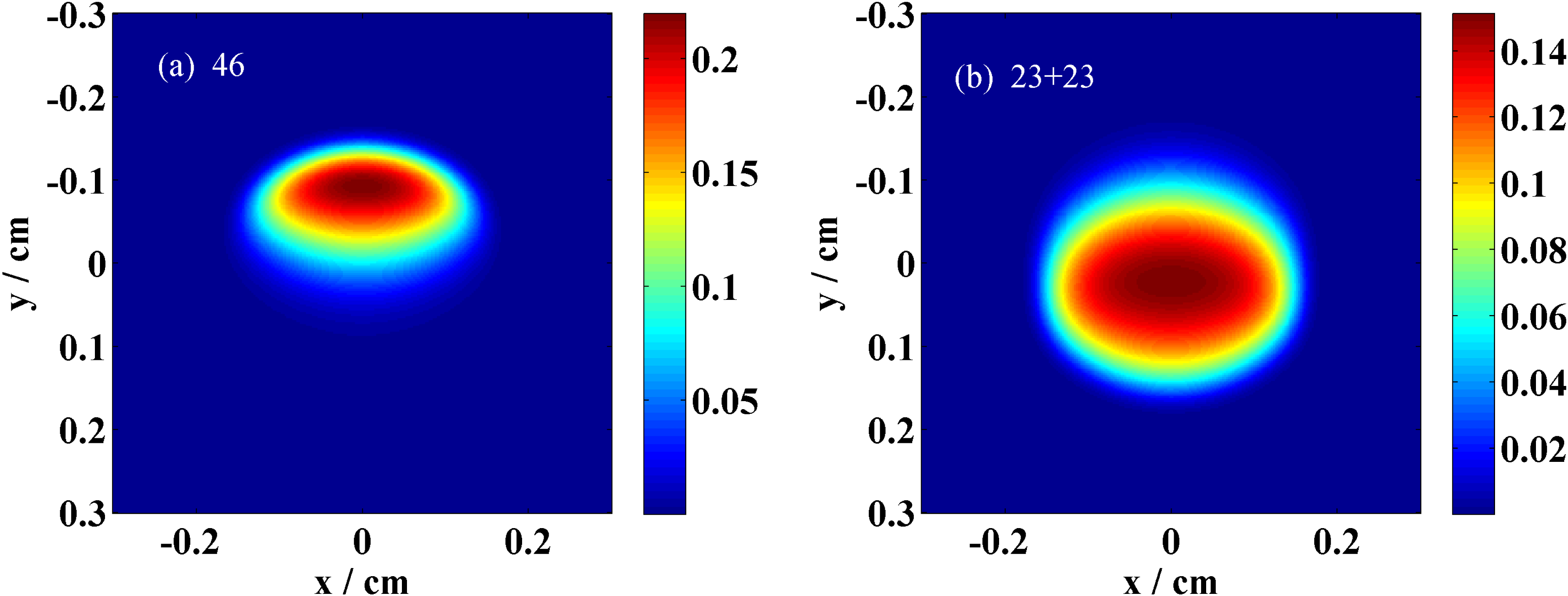
Figure 5. OPCPA stage 1 output signal beam shape from: (a) one 46 mm long crystal; (b) two crystals in ‘L’ type configuration with
![]() $23~\text{mm}+23~\text{mm}$
length.
$23~\text{mm}+23~\text{mm}$
length.

Figure 6. (a) Conversion efficiency and (b) EBP of two BBO crystal combination in ‘L’ type configuration at OPCPA stage 2.
Table 1. Simulation output parameters of OPCPA stage 1.
The simulated output signal parameters of OPCPA stage 1 are shown in Table 1. The spectrum FWHM is about 64 nm for either one long crystal or two crystal combination in the ‘L’ type configuration. The main reason for this result is that OPCPA stage 1 operates in the small signal gain regime, in which the signal gain narrowing is strong and the intensity of idler keeps pretty weak such that the effect of idler dissipation does not play a remarkable role in affecting the bandwidth. But the beam quality can be significantly improved because of the compensation of spatial walk-off in ‘L’ type configuration when the signal gain is at the same order of magnitude.
In OPCPA stage 2, a quantity of energy should be converted to signal from the rest of 370 mJ pump. For obtaining high conversion efficiency here, both spatial and spectrum aspects are deliberated. First, the signal beam from stage 1 is expanded by 5-fold such that the amplified parts can completely match with the pump beam aperture and the pump energy will not be wasted. As to the spectrum, the amplified bandwidth is closely related to the conversion efficiency in stage 2. To reflect the effect of bandwidth optimization on the conversion efficiency, the efficiency bandwidth product (EBP) (EBP equals the product of conversion efficiency and amplified spectrum FWHM) would be the optimizing assessment criteria. Figure 6 shows the color map of conversion efficiency and EBP value versus the crystal length of BBO3 and BBO4 in OPCPA stage 2. The left-most vertical regions of Figures 6(a) and 6(b) represent the OPCPA of one crystal in stage 2. The largest conversion efficiency for only BBO3 is about 43% at the length of 15 mm and a strong back conversion happens when the crystal is longer. However, if a BBO4 crystal of 7 mm length is used after 15 mm BBO3, the efficiency increases to over 50% as the dark red region shows in Figure 6(a). The EBP map shows a similar result just with a longer BBO3, and the largest value is approaching 45 nm. What is interesting is that the two maps show obvious diagonal asymmetry, which means the efficiency and EBP would be quite different (lower) when the crystal length of BBO3 and BBO4 is just exchanged.
This result can be explained by comparing the OPCPA evolutionary process between different crystal length combinations. Figure 7 shows the evolutionary process of OPA of two wavelength components in signal. The length combination of two BBO crystals is
![]() $15~\text{mm}+10~\text{mm}$
in Figures 7(a) and 7(b). 808 nm is the signal’s center wavelength, its phase mismatching with the pump is much smaller than 765 nm (the other wavelength components of the signal have the same result, if their phase mismatching is similar), so the energy of 808 nm is saturated and amplified in the former 15 mm crystal and the pump is depleted completely. Then the amplified idler would be dissipated due to ‘L’ type configuration, as a result, in the next 10 mm BBO4 crystal, the energy of 808 nm signal cannot reconvert to pump alone. Due to the large phase mismatching, the optical parametric process with the pump is slower at 765 nm wavelength, and there is sufficient residual pump energy after 15 mm BBO3. Although the amplified idler is released in the ‘L’ type configuration, the 765 nm signal can still have parametric energy conversion from the pump in the 10 mm BBO4, even if it has reached saturated amplification after BBO3. If the crystal lengths of BBO3 and BBO4 are exchanged, as shown in Figures 7(c) and 7(d), both the signals at wavelengths 808 nm and 765 nm reconvert to pump obviously, leading to low conversion efficiency and EBP value.
$15~\text{mm}+10~\text{mm}$
in Figures 7(a) and 7(b). 808 nm is the signal’s center wavelength, its phase mismatching with the pump is much smaller than 765 nm (the other wavelength components of the signal have the same result, if their phase mismatching is similar), so the energy of 808 nm is saturated and amplified in the former 15 mm crystal and the pump is depleted completely. Then the amplified idler would be dissipated due to ‘L’ type configuration, as a result, in the next 10 mm BBO4 crystal, the energy of 808 nm signal cannot reconvert to pump alone. Due to the large phase mismatching, the optical parametric process with the pump is slower at 765 nm wavelength, and there is sufficient residual pump energy after 15 mm BBO3. Although the amplified idler is released in the ‘L’ type configuration, the 765 nm signal can still have parametric energy conversion from the pump in the 10 mm BBO4, even if it has reached saturated amplification after BBO3. If the crystal lengths of BBO3 and BBO4 are exchanged, as shown in Figures 7(c) and 7(d), both the signals at wavelengths 808 nm and 765 nm reconvert to pump obviously, leading to low conversion efficiency and EBP value.
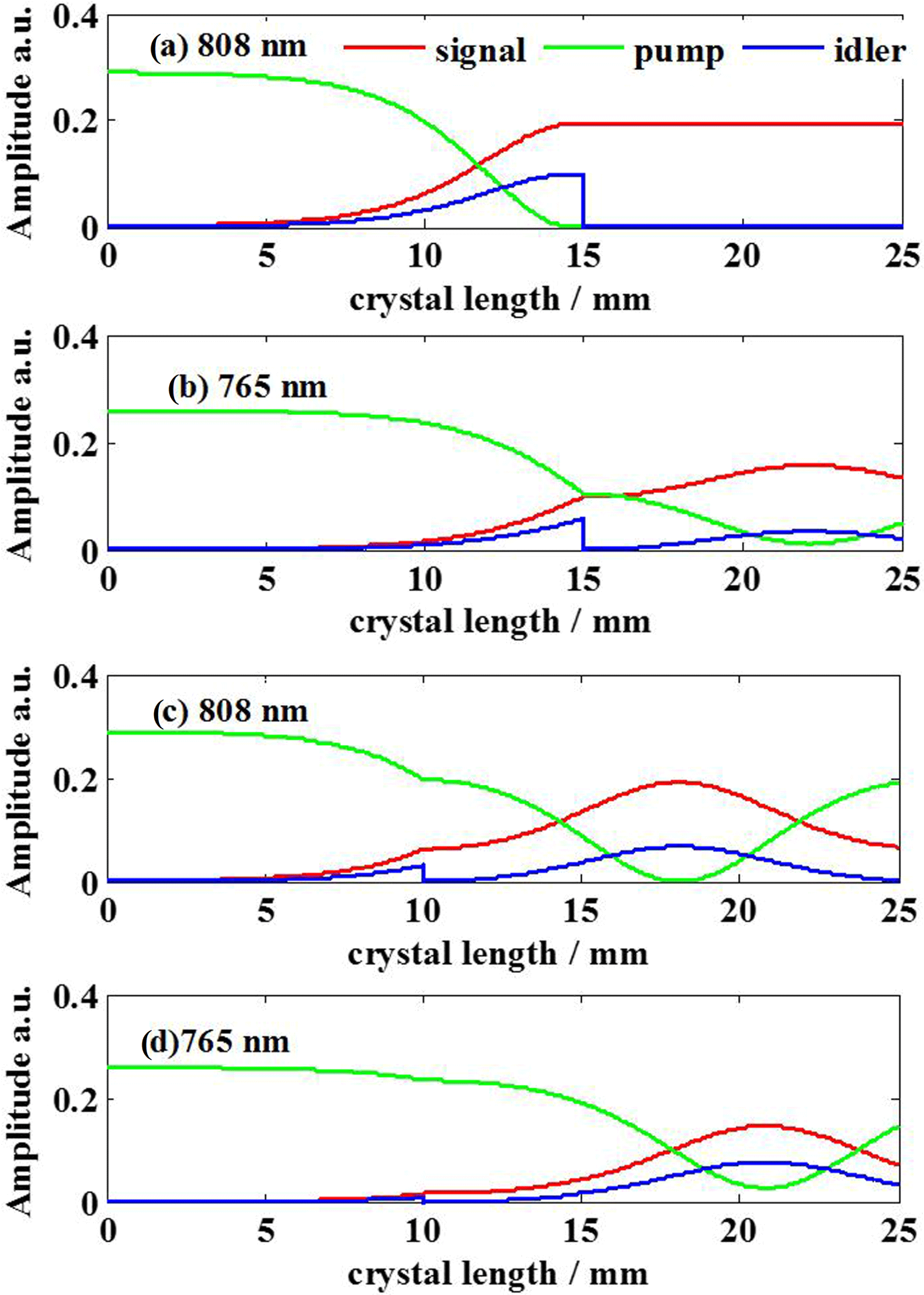
Figure 7. OPA evolutionary process of signal at 808 nm and 765 nm wavelengths in stage 2. Crystals length combination in (a) and (b) is
![]() $15~\text{mm}+10~\text{mm}$
, while in (c) and (d) is
$15~\text{mm}+10~\text{mm}$
, while in (c) and (d) is
![]() $10~\text{mm}+15~\text{mm}$
. Red line represents signal, green line represents pump and blue line represents idler.
$10~\text{mm}+15~\text{mm}$
. Red line represents signal, green line represents pump and blue line represents idler.
In addition to the conversion efficiency and gain bandwidth, the output energy growth curve under the pump energy fluctuation in OPCPA stage 2 is given in Figure 8. A BBO3 crystal of 16 mm length is selected to get the saturated amplification. The dashed lines represent pump energy that fluctuates by
![]() $\pm 5\%$
compared to the nominal value of 450 mJ. The most stable region appears at 11 mm length of BBO4, which is marked as point A in Figure 8. The signal energy variation RMS at this length is smaller than 0.5%, but according to Figure 6, the conversion efficiency and EBP would degrade to 49.5% and 39 nm from 53% and 42 nm at a 7.5 mm long crystal, which is the B point in Figure 8. As a trade-off to be made for the engineering requirement, we chose 9 mm–10 mm long BBO4 to be the appropriate crystal in OPCPA stage 2, because the stability is smaller than 2% and the conversion efficiency and EBP are higher.
$\pm 5\%$
compared to the nominal value of 450 mJ. The most stable region appears at 11 mm length of BBO4, which is marked as point A in Figure 8. The signal energy variation RMS at this length is smaller than 0.5%, but according to Figure 6, the conversion efficiency and EBP would degrade to 49.5% and 39 nm from 53% and 42 nm at a 7.5 mm long crystal, which is the B point in Figure 8. As a trade-off to be made for the engineering requirement, we chose 9 mm–10 mm long BBO4 to be the appropriate crystal in OPCPA stage 2, because the stability is smaller than 2% and the conversion efficiency and EBP are higher.

Figure 8. Signal output energy versus length of two BBO crystals. The first crystal length is 15 mm. The pump energy variation is
![]() $\pm 5\%$
to the initial 450 mJ. A and B correspond to BBO4 crystal lengths of 11 mm and 7.5 mm.
$\pm 5\%$
to the initial 450 mJ. A and B correspond to BBO4 crystal lengths of 11 mm and 7.5 mm.
The signal beam shape output from OPCPA stage 2 is shown in Figure 9. The beam shapes correspond to the positions A and B in Figure 8, where the second crystal length is 11 mm and 7.5 mm, respectively. Spatial variations in saturation and reconversion cause intensity modulation and beam asymmetry in the beam shape of Figure 9(a) although the stability is best here. Figure 9(b) shows that a more uniform beam shape is obtained at point B with a little spatial walk-off in
![]() $y$
direction, and the walk-off is stronger when the crystal length goes to 9 mm as shown in Figure 9(c). Even so, the beam shape for crystal length of 9 mm is still much better than that of 11 mm. The final optimized crystal lengths of OPCPA stage 2 for BBO3 and BBO4 are 16 mm and 9 mm, respectively and the corresponding output parameters are presented in Table 2.
$y$
direction, and the walk-off is stronger when the crystal length goes to 9 mm as shown in Figure 9(c). Even so, the beam shape for crystal length of 9 mm is still much better than that of 11 mm. The final optimized crystal lengths of OPCPA stage 2 for BBO3 and BBO4 are 16 mm and 9 mm, respectively and the corresponding output parameters are presented in Table 2.

Figure 9. Signal output beam shape of OPCPA stage 2 for different lengths of BBO4 crystal. (a): 11 mm; (b) 7.5 mm; (c) 9 mm.
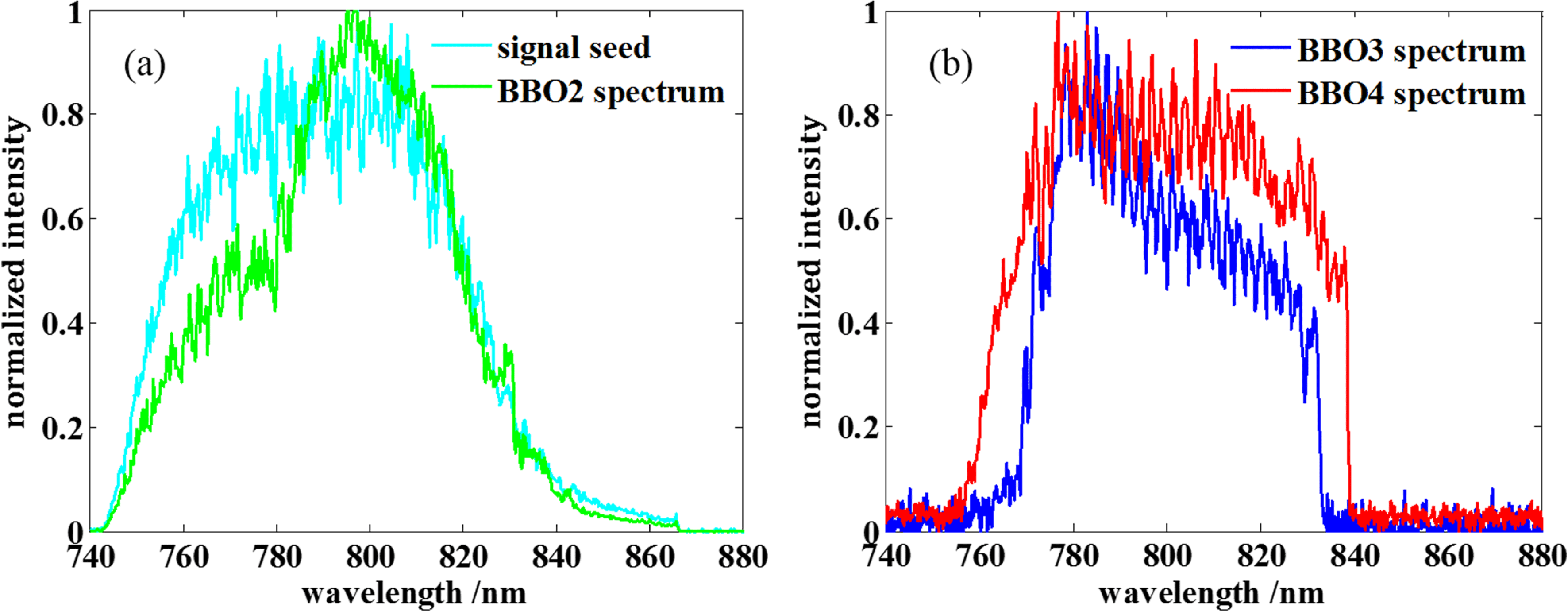
Figure 10. Measured experimental output signal spectrum from different OPCPA stages. (a) Spectra from signal seed (cyan line) and BBO2 (green line); (b) spectra from BBO3 (blue line) and BBO4 (red line).
Table 2. Simulation output parameters of OPCPA stage 2.
3 Experiment
Our optimized OPCPA pre-amplifier has been experimentally demonstrated. All the parameters are the same as the OPCPA amplifier design in Section 2. Figures 10(a) and 10(b) are the output signal spectra from OPCPA stages 1 and 2, respectively. The spectra are all measured by the Ocean Optics fiber spectrometer. Compared to the seed spectrum, the output signal spectrum from BBO2 shows obvious gain narrowing especially near the 770 nm wavelength. The bandwidth of the output signal after OPCPA stage 1 is 62 nm and the corresponding transform-limited pulse duration is 16 fs. (According to the Fourier transform formula of Gaussian type pulse:
![]() $\unicode[STIX]{x0394}\unicode[STIX]{x1D706}\unicode[STIX]{x0394}t=2\ln (2)\times \unicode[STIX]{x1D706}_{0}^{2}/\unicode[STIX]{x03C0}c$
, where
$\unicode[STIX]{x0394}\unicode[STIX]{x1D706}\unicode[STIX]{x0394}t=2\ln (2)\times \unicode[STIX]{x1D706}_{0}^{2}/\unicode[STIX]{x03C0}c$
, where
![]() $\unicode[STIX]{x1D706}_{0}$
is the central wavelength and
$\unicode[STIX]{x1D706}_{0}$
is the central wavelength and
![]() $c$
is the light velocity.) After the saturation amplification in the BBO3, the dip near 770 nm wavelength was filled up and the FWHM was increased to 65 nm. The final output spectrum from BBO4 was more flattened and the wavelength at the side of the spectrum obtained large energy gain especially around 840 nm. In addition to the influence of idler dissipation, the phase matching in BBO4 was slightly adjusted to make the energy growing easier around 840 nm. The final FWHM of output spectrum bandwidth is broadened to 80 nm and its corresponding transform-limited pulse duration is 12 fs. This experimental phenomenon agrees well with the numerical simulation results shown in Figure 6(b). The output parameters have been listed in Table 3. The signal energy of both 2 stages amplification chain is 160 mJ, which corresponds to a total pump-to-signal efficiency of 35% with
$c$
is the light velocity.) After the saturation amplification in the BBO3, the dip near 770 nm wavelength was filled up and the FWHM was increased to 65 nm. The final output spectrum from BBO4 was more flattened and the wavelength at the side of the spectrum obtained large energy gain especially around 840 nm. In addition to the influence of idler dissipation, the phase matching in BBO4 was slightly adjusted to make the energy growing easier around 840 nm. The final FWHM of output spectrum bandwidth is broadened to 80 nm and its corresponding transform-limited pulse duration is 12 fs. This experimental phenomenon agrees well with the numerical simulation results shown in Figure 6(b). The output parameters have been listed in Table 3. The signal energy of both 2 stages amplification chain is 160 mJ, which corresponds to a total pump-to-signal efficiency of 35% with
![]() ${>}43\%$
efficiency in the OPCPA stage 2. The efficiency is comparable with that of 41% achieved by OPA[Reference Ma, Wang, Yuan, Xie, Xiong, Tu, Tu, Shi, Zheng and Qian17], and the output energy stability was measured to be 1.67% RMS as shown in Figure 11.
${>}43\%$
efficiency in the OPCPA stage 2. The efficiency is comparable with that of 41% achieved by OPA[Reference Ma, Wang, Yuan, Xie, Xiong, Tu, Tu, Shi, Zheng and Qian17], and the output energy stability was measured to be 1.67% RMS as shown in Figure 11.
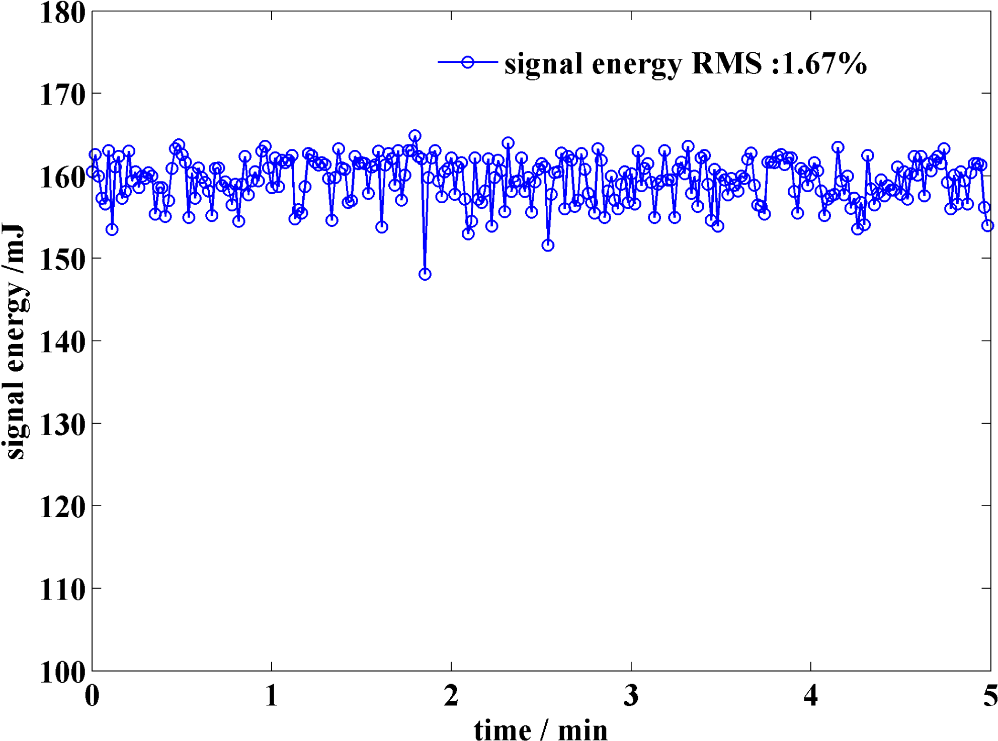
Figure 11. Measurement of the output energy over 5 min.
Table 3. Experimental output parameters.

The measured spatial beam profile of the amplified signal is shown in Figure 12, where the arc of deep red on the right indicates a little walk-off in
![]() $y$
direction. The compression of the amplified signal pulse was achieved with the main compressor used in SG-II 5PW laser facility[Reference Andrianov, Szabo, Sergeev, Kim, Chvykov and Kalashnikov20]. The compressed pulse traces, measured by a home-made autocorrelator[Reference Yang, Cui, Kang, Guo, Zhu, Sun, Zhu, Gao, Xie and Zhu21], are shown in Figure 13. The FWHM of pulse duration is 24 fs and a substantially uncompressed pedestal can be seen in the pulse traces, which in our opinion mainly derives from the integral effect of chromatic aberrations in the laser system. There are two reasons for the compressed pulse duration being wider than the transform-limited pulse duration given above. One is that the pulse width is measured with the whole beam diameter by shrinking the beam from
$y$
direction. The compression of the amplified signal pulse was achieved with the main compressor used in SG-II 5PW laser facility[Reference Andrianov, Szabo, Sergeev, Kim, Chvykov and Kalashnikov20]. The compressed pulse traces, measured by a home-made autocorrelator[Reference Yang, Cui, Kang, Guo, Zhu, Sun, Zhu, Gao, Xie and Zhu21], are shown in Figure 13. The FWHM of pulse duration is 24 fs and a substantially uncompressed pedestal can be seen in the pulse traces, which in our opinion mainly derives from the integral effect of chromatic aberrations in the laser system. There are two reasons for the compressed pulse duration being wider than the transform-limited pulse duration given above. One is that the pulse width is measured with the whole beam diameter by shrinking the beam from
![]() $290~\text{mm}\times 290~\text{mm}$
to
$290~\text{mm}\times 290~\text{mm}$
to
![]() $5~\text{mm}\times 5~\text{mm}$
. Therefore, the spatial–temporal couplings among the spatial filters and the compressor will influence the pulse compression. Another reason is that the transform-limited pulse duration of super Gaussian profile is basically larger than Gaussian profile.
$5~\text{mm}\times 5~\text{mm}$
. Therefore, the spatial–temporal couplings among the spatial filters and the compressor will influence the pulse compression. Another reason is that the transform-limited pulse duration of super Gaussian profile is basically larger than Gaussian profile.

Figure 12. CCD measured output signal near-field at 161 mJ.

Figure 13. Measured compressed pulse duration by an autocorrelator.
While there is not much effective method to suppress optical parametric fluorescence (OPF) during the OPCPA process, we also make some measures to control it as much as possible. First, the pump pulse width must be smaller than that of the signal and they have to be synchronized precisely; second, all of the crystals are cut with
![]() $1^{\circ }$
wedge angles at the rear face and coated on the surfaces with 532 nm and 808 nm broadband antireflective films. What is more, the beam expander which also can act as a spatial filter between two OPCPA stages is aligned with a pinhole to suppress the high-frequency modulations and the OPF generated in the amplification. Portion of the OPF transmits as high order angular spectra can be significantly suppressed by the pinholes in the spatial filters.
$1^{\circ }$
wedge angles at the rear face and coated on the surfaces with 532 nm and 808 nm broadband antireflective films. What is more, the beam expander which also can act as a spatial filter between two OPCPA stages is aligned with a pinhole to suppress the high-frequency modulations and the OPF generated in the amplification. Portion of the OPF transmits as high order angular spectra can be significantly suppressed by the pinholes in the spatial filters.
4 Conclusion
The design and experimental study were carried out for a high efficiency OPCPA pre-amplifier based on the BBO crystal. By introducing ‘L’ type configuration into two OPCPA stages, we theoretically analyzed its effect on the optimization of conversion efficiency, bandwidth and beam quality. In the high gain region such as OPCPA stage 1, the small signal gain does not recede due to the elimination of idler, but the gain is little higher than the traditional OPCPA of one crystal because the spatial walk-off is compensated between two crystals. The conversion efficiency and bandwidth are greatly improved in the OPCPA stage 2, and the back conversion after the saturated amplification can be prevented by dissipating the idler pulse at certain length of first BBO crystal in ‘L’ type configuration. In consideration of energy stability, 16 mm length of BBO3 and 9 mm–10 mm length of BBO4 were finally selected for OPCPA stage 2.
In the experiment, the output spectra of two OPCPA stages are in conformity with the theoretical expectation. The total pump-to-signal efficiency is 35% with output energy of 160 mJ and 1.67% RMS energy stability. The efficiency in OPCPA stage 2 is over 43%, which is a quite high efficiency in one OPCPA amplifier. The new designed OPCPA pre-amplifier will be used in the SG-II 5PW laser facility to improve the performance in the near future.
Acknowledgement
This work was partially supported by the National Natural Science Foundation of China (NSFC) (Nos. 11304332, 11704392, and 61705245).


