Introduction
Since the late 1990s, when the first studies on oriented attachment (OA) of crystals were published (Penn and Banfield, Reference Penn and Banfield1998; Reference Penn and Banfield1999; Banfield et al., Reference Banfield, Welch, Zhang, Ebert and Penn2000), this non-classical mechanism of crystal formation has been researched extensively. Although numerous studies have been conducted previously (Ivanov et al., Reference Ivanov, Fedorov, Ye. Baranchikov and Osiko2014), non-classical crystallization has only been recognized widely in the past few years. Evidence of crystallization in biogenic and synthetic materials (e.g. metal oxides, selenides and sulfides) by particle attachment is demonstrated in numerous contributions, and this process has even been observed directly by high-resolution transmission electron microscopy (HRTEM) using a fluid cell (Li et al., Reference Li, Nielsen, Lee, Frandsen, Banfield and De Yoreo2012). However, efforts to establish the contribution of the particle attachment mechanism to inorganic crystallization in natural environments have barely begun (De Yoreo et al., Reference De Yoreo, Gilbert, Som-merdijk, Penn, Whitelam, Joester, Zhang, Rimer, Navrot-sky, Banfield, Wallace, Michel, Meldrum, Cölfen and Dove2015). In this work, we present for the first time evidence that confirms oriented particle attachment as a crystal growth mechanism that is relevant in sedimentary environments. In these natural settings, oriented particle attachment operates during the formation of the structurally highly anisotropic clay minerals, which constitute one of the most extensively distributed groups of minerals in the Earth's crust.
The classical theory of crystallization assumes the incorporation of individual ions or molecules onto high-energy crystal faces. However, after the pioneering work of Penn and Banfield (Reference Penn and Banfield1998), today, it is generally accepted that crystals can also grow by the oriented addition of clusters, nanoparticles, or even micrometric crystals (Viedma et al., Reference Viedma, McBride and Kahr2013). The formation of (single) crystals through oriented self-assembly into superstructures, followed by later fusing of nanoparticles originated in parallel multiple nucleation events, is included within the category of ‘nonclassical crystallization’. Oriented attachment generates mesocrystals that are defined as kinetically stabilized superstructures of nanocrystals arranged in crystallographic co-alignment (Penn, Reference Penn2004) in which the primary units can still be identified. Therefore, mesocrystals are an intermediate step between dispersed particles and true single crystals (Colfen and Antonietti, Reference Colfen and Antonietti2008). The first references to crystallization by OA were related mainly to Fe, Ti or Zn synthetic oxides (Penn, and Banfield, Reference Penn and Banfield1998; Reference Penn and Banfield1999; Penn et al, Reference Penn, Oskam, Strathmann, Searson, Stone and Veblen2001, Niederberger, et al., Reference Niederberger, Krumeich, Hegetschweiler and Nesper2002, Cozzoli et al., Reference Cozzoli, Curri, Agostiano, Leo and Lomascolo2003) and other synthetic compounds, such as sulfides (Zhang, Reference Zhang2000; Ricolleau, Reference Ricolleau, Audinet, Gandais and Gacoin1999) or zeolites (Nikolakis et al., Reference Nikolakis, Kokkoli, Tirrell, Tsapatsis and Vlachos2000). After these studies, hundreds of references have described OA for a diverse range of synthetic compounds. Oriented attachment has often been argued as the mechanism responsible for the formation of natural biogenic iron-oxide nanoparticles (Banfield et al., Reference Banfield, Welch, Zhang, Ebert and Penn2000). In more recent experimental studies, OA has been proposed as a possible mechanism for the formation of todorokite in deep-sea polymetallic nodules (Atkins et al., Reference Atkins, Shaw and Peacock2014). Oriented attachment has even been proposed for the growth of crystals not only from solutions but also from melts (Helmy et al., Reference Helmy, Ballhaus, Fonseca, Wirth, Nagel and Tredoux2013). Consequently, OA has been used to explain the existence of platinum-group elements in pentlandite (Junge et al., Reference Junge, Richard, Oberthür, Melcher and Schreiber2015) but has never been demonstrated. In a previous work, we have shown evidence of mesocrystals of sepiolite and palygorskite (García-Romero and Suárez, Reference García-Romero and Suárez2014).
Clay minerals are ubiquitous in the Earth's surface environments, where they form mainly by hydrolysis from less stable silicates and by direct precipitation from solutions. Apart from their importance as rock-forming minerals and palaeoenvironmental indicators, the properties of clays are highly advantageous in numerous industries. In this study, we provide evidence to support the claim that the growth of clay minerals in sedimentary environments occurs mainly by OA. Furthermore, compared to classical mechanisms, we state that, due to the structural characteristics of clay minerals, OA is a much more efficient mechanism for their crystal growth, and it is the only mechanism that can account for the development of their specific morphological features. The process has been proven herein using HRTEM images of clay minerals.
Methods
High-resolution TEM imaging was conducted at the Centro Nacional de Microscopía Electrónica (Spain). Clay minerals are extremely beam-sensitive compared to other non-hydrated minerals, posing a higher level of difficulty for HRTEM imaging. Therefore, samples must be prepared under special conditions to prevent beam damage. The experimental conditions were optimized to avoid structural modification using a low beam intensity (<500 counts on the CCD camera) with an exposure time of 0.8 s to acquire the image. The samples were prepared via two methods: the conventional method of depositing a drop of dilute clay suspension onto a microscope Cu grid with cellulose acetate butyrate; and by studying ultrathin sections of undisturbed samples. The samples underwent treatments to preserve the microtexture and avoid the collapse of the smectite interlayer space. These treatments are conducted in a sequence of successive steps where a small portion of sample is placed in agar-agar to protect it from future stains. The sample must then be hydrated and the water progressively replaced by alcohol; afterwards the alcohol is replaced by Spurr resin, according to the methodology proposed by Tessier (Reference Tessier1984) and Tessier and Pedro (Reference Tessier, Pedro, Shultz, van Olphen and Mumpton1987). After polymerization of the resin, thin sections (50 nm) were cut by ultramicrotomy. This procedure minimizes dehydration during HRTEM study and thus helps preserve the natural texture of the sample. The observations were performed using a JEOL 3000 FX field-emission microscope with a LaB6 filament at an acceleration voltage of 300 kV with 0.17 nm point-to-point resolution, equipped with a double-tilt sample holder (up to a maximum of ±23°) and a CCD camera for digitally recording the images. The images shown herein have been selected from the authors' photo collections. The samples come from different localities around the world that have been studied previously by the authors, with different objectives.
Evidence of oriented aggregation in clay minerals by HRTEM observations
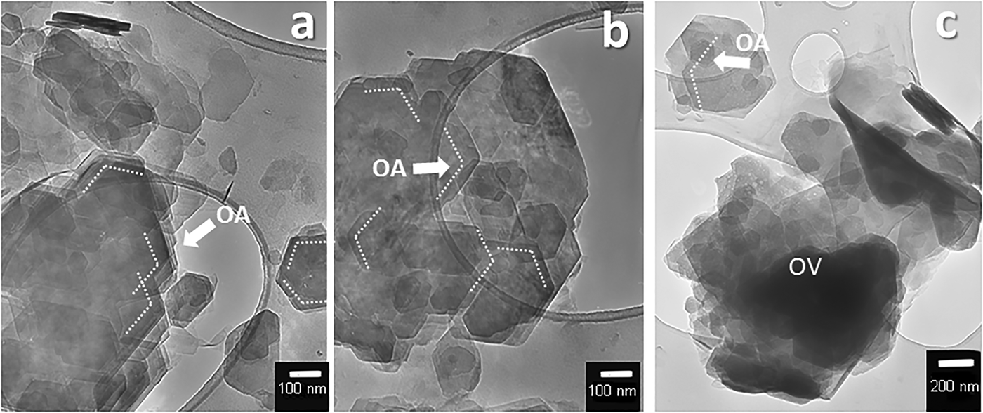
The HRTEM images of different clay minerals (kaolinite, smectite, and sepiolite–palygorskite) indicate that all are composed of small crystallites. Close inspection reveals that the crystallites are in turn composed of smaller subunits, and that structural and textural peculiarities of the different clay minerals are related to the arrangement of these subunits. Figure 1 has been obtained from the sedimentation of kaolinite particles on the grid. In these images, kaolinite appears as pseudohexagonal plates of different sizes. The smaller particles that appear overlapped mostly have the same crystallographic orientation (indicated as OA in Fig. 1), and they can be distinguished perfectly from the misoriented overlapping particles (indicated as OV in Fig. 1c). The oriented overlapping indicates the aggregation of individual units forming larger particles, while the misoriented overlapping is the result of sedimentation of different particles on the grid that have, in this case, different orientations. The size of the crystals that aggregate to form the kaolinite mesocrystals ranges from 50 nm to 500 nm.

Fig. 1. HRTEM images of pseudohexagonal kaolinite particles obtained by sedimentation on the grid. The smaller size plates are usually overlapped in the same crystallographic orientation on the bigger ones (a, b), while rarely misoriented (c). OA: Oriented aggregation. OV: overlapped. Samples come from Tamame de Sayago deposit, Zamora, Spain.
High-resolution TEM images of the smectite show that this clay mineral occurs as lenticular packets with elongate sigmoidally curved cross-sections (Fig. 2 and 3) and tapered margins. These particles are usually no larger than 1 µm long by 50 nm wide at their central part. Under higher magnification, lattice planes with a spacing of 14 Å become visible with numerous stacking faults and edge dislocations. The stacking defects concentrate near particle edges (Figs 2 and 3). This lattice spacing matches that expected from the stacking of smectite structural units (the 2:1 layers) along the c-axis direction. It is interesting to note that smectite particles also usually consist of smaller, similar individual particles (like smaller sigmoid) (Figs 2 and 3), indicating that they originated by the addition of minor single particles. The shapes of these particles are a direct consequence of their mode of attachment. In the smectites, the aggregation of the minor single particles (or even isolated layers) that forms the larger particles occurs in a staggered manner by semi-oriented attachment, generating multiple stacking faults and dislocations, as observed in Figs 2 and 3, as is usual for this type of attachment process (De Yoreo et al., Reference De Yoreo, Gilbert, Som-merdijk, Penn, Whitelam, Joester, Zhang, Rimer, Navrot-sky, Banfield, Wallace, Michel, Meldrum, Cölfen and Dove2015). Dislocations and line defects are frequently found next to the interface between the adjacent oriented particles as a consequence of the fit between them, as described by Banfield et al. (Reference Banfield, Welch, Zhang, Ebert and Penn2000). In some cases, the interface between the two units is still distinguishable, as in Fig. 4, which shows a detail of the interface between two laminar particles of illite in which its constituent primary units can be distinguished.

Fig. 2. (a–e) HRTEM smectite images. The particles have a common sigmoidal appearance. Note the parallel lattice planes and the small subunits that form the larger particles. The subunits are thick in their central portions with tapered margins and curved cross-sections. They have numerous stacking faults and edge dislocations. The minor units that compose the particle in (d) are highlighted in (e). Samples (a) and (c) come from Cortijo de Archidona deposit, Almeria, Spain. Sample (b) comes from Esquivias deposits, Tagus Basin, Spain. Samples (d) and (e) come from The Green Clays Unit, Tagus Basin, Spain.

Fig. 3. HRTEM smectite images. Particles formed by the attachment of minor particles. (a,b) Particles of smectite where the parallel lattice planes are observable. They have numerous stacking faults concentrated near the interface of two aggregated particles. The central part of the particles hardly ever has stacking faults. (c,d) The same particles in which the lattice planes, and the units that form them, have been marked. The white arrows indicate areas of higher density of stacking faults. The dark arrows indicate the areas where the parallel lattice planes are free of stacking faults. Samples come from Cortijo de Archidona deposit, Almeria, Spain.

Fig. 4. HRTEM smectite image showing the interface along the union of the two laminar particles (illite). The sample comes from The Green Clays Unit, Tagus Basin, Spain.
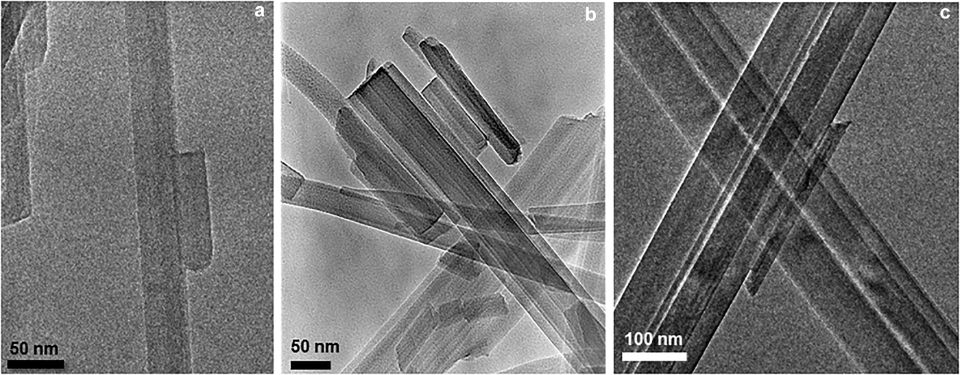
In the same way, HRTEM images of natural sepiolite and palygorskite samples show that fibres, irrespective of length are composed of finer-width subunits (Fig. 4) (García-Romero and Suárez, Reference García-Romero and Suárez2014). The length of the fibres varies from <1 µm to centimetres (in some instances) with no gap. The smaller and primary units, named laths, are prismatic and elongated in the c-axis direction, are 10–30 nm in width (Fig. 5), and are parallelogram-shaped in cross-section. These images also indicate that after nucleation, the laths join to form larger units. The TEM images show that the mesocrystals of sepiolite and palygorskite are formed by the attachment of laths, of differing lengths, sharing (hk0) faces. In fibrous crystals, the aggregation of the smallest units (laths) to generate mesocrystals has also been observed in synthetic todorokite (Atkins et al., Reference Atkins, Shaw and Peacock2014).

Fig. 5. TEM images of sepiolite–palygorskite sedimented on the grid. The prismatic, elongated particles in the c-axis direction are formed by the attachment of minor ones. Sample (a) comes from the Gran County deposit, New Mexico, USA. Sample (b) comes from the Warren deposit, Texas, USA. Sample (c) comes from the Metaline fault deposit, Washington, USA.
Structural evidence supporting OA in clay minerals
After the nucleation stage, the growth of a crystal is controlled by the energy of its binding surfaces, which in turn are controlled by the crystal structure. Clay minerals layers have a highly anisotropic structure built from sheets which stack in the c direction (Figs 6a and b). Each layer in turn is composed of an octahedral sheet containing larger cations (Mg, Al or Fe depending on the mineral species) in octahedral coordination by OH– and O2–, linked to one or two tetrahedral sheets containing Si in tetrahedral coordination by O2–. Kaolinite crystals are formed by stacked layers composed of one tetrahedral sheet and one octahedral sheet (T–O) in a 1:1 structure type (Fig. 6a). Kaolinite layers have very few isomorphic substitutions; consequently, they do not have charge or interlayer cations. Additionally, their stacking is due to van der Waals bonds between a face with OH– groups corresponding to an octahedral sheet and another face that is a basal oxygen plane. Smectite crystals are composed of stacked layers formed by one octahedral sheet between two tetrahedral sheets (T–O–T) in a 2:1 structure type (Fig. 6b). Smectite 2:1 layers have numerous isomorphic substitutions in tetrahedral (Si4+ replaced by Al3+) and octahedral positions creating a layer charge, which is compensated by solvated cations in water (Mg2+, Ca2+, Na+ or K+) placed in the interlayer space, named interlayer cations. The weakly charged layers are held together by electrostatic attraction with the cations. Smectite (001) and (00![]() $\bar 1$) surfaces are the same because they are formed by the basal oxygen planes of the two tetrahedral sheets and are surrounded by solvated cations. Therefore, for the phyllosilicates, bonding within sheets is strong, while bonding between two consecutive layers is weaker, and the forces that hold the layers together are the same forces that attract the individual crystals to each other and cause them to aggregate.
$\bar 1$) surfaces are the same because they are formed by the basal oxygen planes of the two tetrahedral sheets and are surrounded by solvated cations. Therefore, for the phyllosilicates, bonding within sheets is strong, while bonding between two consecutive layers is weaker, and the forces that hold the layers together are the same forces that attract the individual crystals to each other and cause them to aggregate.

Fig. 6. Structural scheme of phyllosilicates: (a) kaolinite (T–O); (b) smectite (T–O–T); (c) sepiolite/palygorskite (T–O–T). Tetrahedral cations: Si4+, which can be replaced by Al3+. Octahedral cations: Mg, Al, Fe2+ or Fe3+ Interlayer cations: Mg2+, Ca2+, Na+ or K+ solvated by water.
It is remarkable that in these minerals, there is no possibility to grow in the c direction by the addition of atoms or molecules in a classical crystal growth process. Both smectite and kaolinite have compound octahedral-tetrahedral layers (Figs 6a and b) within which all changes are internally compensated, which prevents the addition of isolated ions in the c direction. Thus, the (001) faces parallel to the layers, formed by basal oxygen planes, are atomically flat, with no growth steps. The only possibility for growth in this direction is attachment of major units, i.e. oriented attachment of platelets comparable in lateral extent to the initial crystal. However, the (hk0) faces have Si–O, M–O, and M–OH broken bonds, so they are rough (Fig. 6a and b). Therefore, as shown in Fig. 7, these (hk0) faces have growth steps, as in most silicates, and according to the classical growth theory the crystals can grow by atom-by-atom addition in the a and b directions. The weak attraction between two layers leads to their fusion on an energetically favourable process because it eliminates the two high-energy-surfaces. After a nucleation stage, the laminar particles of these clay minerals can grow by atom-by-atom addition in the [hk0] direction but only by OA in the [00l] direction, resulting in anisotropically shaped particles only a few nm thick in the c direction.

Fig. 7. Edge of smectite crystal, corresponding to a (hk0) face. It has numerous growth kinks, and a rough face with Si–O, M–O, and M–OH bonds broken. In this face, the crystals can grow by atom-by-atom addition in this direction. The sample comes from The Pink Clays Unit, Tagus Basin, Spain.
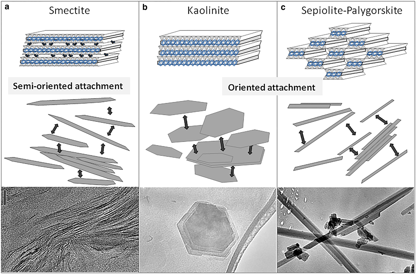
Kaolinite particles are formed by the stacking of several T–O layers in the [00l] direction, and the aggregation is favoured by the opposite polar charge of each sheet. The tetrahedral sheet has a negative polar charge, while the octahedral sheet has a positive polar charge; then when they aggregate, the tetrahedral sheet joins to the octahedral sheet only by elimination of the oriented water molecules at the interfaces, as previously described (Banfield et al., Reference Banfield, Welch, Zhang, Ebert and Penn2000) for iron oxyhydroxides. Likewise, smectite particles are formed by the stacking of several T–O–T layers. Unlike what occurs in kaolinite (Figs 1 and 8b), the smectite layers usually aggregate in a staggered manner (semi-oriented attachment) as described in De Yoreo et al. (Reference De Yoreo, Gilbert, Som-merdijk, Penn, Whitelam, Joester, Zhang, Rimer, Navrot-sky, Banfield, Wallace, Michel, Meldrum, Cölfen and Dove2015), causing the particles to exhibit a sigmoidal cross-section (Figs 2, 3 and 8a). The explanation for the staggered aggregation of layers must reside in the interlayer solvated cations. Additionally, staggering avoids the repulsive forces between two contiguous edges of layers because both are charged positively. The aggregation is easier when the position of the edge of a layer is near the face of the contiguous layer. In this manner, the positively charged edge of a layer is next to the negatively charged face of the next layer. In this configuration, positive charges of the broken octahedral bonds and the negative tetrahedral surface attract, which results in the sigmoidal shape of the particles. Smectite primary particles that aggregate are surrounded by hydrated cations. For two layers to join, they need to expel half of the cations. Additionally, in contrast to what occurs in kaolinite, as a result of the aggregation with a small angle the smectite particles have a high number of stacking defects (edge dislocations) near the edge of the particles (Fig. 3). The defects appear to accommodate the structural differences between two particles. In the same way, small particles attach to each other to form larger particles. The aggregation phenomenon is responsible for the inclusion of the high number of defects, such as twists, disorientation, or tilts observed by HRTEM in clay minerals, notably in smectite (Figs 2 and 3).

Fig. 8. Scheme of oriented aggregation in clay minerals. (a) Smectite. Particles with sigmoidal appearance are a consequence of their aggregation of several T–O–T layers in a staggered manner (semi-oriented attachment). Staggering avoids the repulsive forces between two contiguous edges of layer because both are charged positively, resulting in the sigmoidal shape of particles. (b) Kaolinite. Stacking of T–O layers in [00l] direction. The aggregation will be favoured by the opposite polar charge of each sheet. (c) Sepiolite/palygorskite. The apical oxygens of the silica tetrahedral sheet are periodically inverted, producing discontinuous octahedral sheets in the [0k0] direction, and resulting in ribbons or polysomes along the [00l] direction, as well as tunnels and channels.
In contrast, the (hk0) faces have a high number of kinks and very high attachment energy because they correspond to the edge of layers where both the tetrahedra and octahedra have broken bonds (Fig. 6). Therefore, in these faces, growth by atom-by-atom addition is possible. An image of the termination of the layers in a (hk0) face in a smectite is shown in Fig. 8. Although the energy decreases greatly when the addition of atoms completes the kinks, it returns (increases) to the previous level immediately after incorporation; thus, the crystal growth in this direction occurs by monomer addition.
Sepiolite and palygorskite are the end-members of a continuous polysomatic series (Suarez and García-Romero, Reference Suarez and García-Romero2013). In these fibrous clays, the apical oxygen atoms of the silica tetrahedral sheet are periodically inverted. This periodic inversion produces discontinuous octahedral sheets in the [010] direction, resulting in ribbons or polysomes along the [001] direction (Fig. 6c). Each ribbon is two silicate chains wide in palygorskite and three chains wide in sepiolite. Palygorskite contains Al and Mg as octahedral cations, while sepiolite contains only Mg. The discontinuity in the octahedral sheet leads to the formation of tunnels at the inner and channels at the crystal edge, which run parallel to the c axis of the crystal. In both minerals, Mg occupies the octahedral position located at the polysome edge and completes its coordination sphere with two water molecules. In the (00l) faces, tetrahedral and octahedral sheets have broken bonds (Fig. 6c), and have high attachment energy (rough faces); therefore, the crystals can achieve growth by monomer addition, such as laminar clay minerals in the (hk0) directions. With this mechanism, the fibres can become longer but not wider because the a and b directions (hk0) lead to flat faces. In these flat faces, the atoms do not find kink growth. The (h00) faces have the basal oxygen planes and finish in the channel, and the same occurs with the (0k0) faces in which octahedral sheets finish with terminal octahedral cations bonded to water molecules. In these directions, it is impossible to achieve atomic growth by addition, while the only possibility for growth on the (hk0) faces is by the addition of complete units, such as in laminar clay minerals. However, in these cases, the units are the polysomes (or laths as larger units). The growth in the (hk0) directions is therefore by an oriented aggregation process, as shown in Fig. 8c. The oriented attachment of polysomes occurs along the fibre through the Si–O–Si bonds of alternating polysomes by an oxalation process in which a water molecule forms.
To summarize, the morphology of the resulting clay mineral crystals, both laminar (kaolinite and smectite) and fibrous (sepiolite–palygorskite), is controlled by the strong variation in attachment energy between different faces. The existence of crystal surfaces without broken bonds, and as a consequence weak attachment energy (001) in laminar and (hk0) in fibrous clay minerals, explains crystal growth by oriented aggregation. Smectites aggregate by semi-oriented attachment (Fig. 8a), while kaolinite, sepiolite and palygorskite aggregate by oriented attachment (Fig. 8b and c). Growth by the atom-to-atom addition is possible only in the directions containing broken bonds, and consequently high attachment energy: the (hk0) faces in laminar phyllosilicates and the (001) faces in fibrous ones.
Acknowledgements
The authors acknowledge Dr. Lurdes Fernandez-Díaz and Dr. Cristobal Viedma for their valuable comments and the MINECO CGL2016-77005R project for providing financial support.


