Nomenclature
- A
-
empirical stress value
- B
-
empirical stress value
- C
-
empirical dimensionless constant
- n
-
empirical dimensionless constant
- m
-
empirical dimensionless constant
- T
-
current test temperature
- T melt
-
melting point of the material
- T r
-
room temperature
-
 ${\sigma _e}$
-
equivalent stress
-
 $\varepsilon _e^{\mathop{\rm p}\nolimits} $
-
plastic strain
-
 $\dot \varepsilon $
-
strain rate
-
 ${\dot \varepsilon _0}$
-
reference strain rate
-
 ${{\mathop {\dot \varepsilon }\limits^ \bullet } \mathord{\left/ {\vphantom {{\mathop {\dot \varepsilon }\limits^ \bullet } {\mathop {{{\dot \varepsilon }_0}}\limits^ \bullet }}} \right.} {\mathop {{{\dot \varepsilon }_0}}\limits^ \bullet }}$
-
strain rate
-
 ${\varepsilon _{fail}}$
-
equivalent plastic strain of failure
1.0 Introduction
With the maturity of UAV-related technologies and increasing demand for UAV systems, UAVs have been widely used in many fields, such as emergency rescue, environmental monitoring, power line inspection, aerial surveying and mapping, agricultural and forestry plant protection and cargo transportation. However, the rapid increase in drones has led to a sharp increase in aviation safety hazards and accident symptoms. There have been many incidents of collision and dangerous approaching between drones and aircraft in the United States, Canada, Britain, Mozambique and other countries [Reference Liu1]. Although no collision incidents have occurred in China at present, there have been more than 100 incidents of drones invading flight control areas or approaching aircrafts dangerously since 2013. The “black fly” and “interference” cases have resulted in many flights being adjusted, aircrafts being avoided, alternated, delayed, grounded and even airport being closed, and the trips of over million passengers have been affected average annual, which has a great effect on the safe operation of aviation transportation and would incite aviation safety worries in the public [Reference Quan, Li, Bai, Fu, Li, Ke and Cai2–Reference Sun, Chang and Bai5]. Because of the various configurations, diversiform functions, rapid updating and different compositions of UAVs from the tissue structure of birds, the consequences of collisions between UAV and aircraft have not been comprehensively and systematically studied, and there is no relevant airworthiness clause to constrain their collision safety. Although airworthiness of aircraft against bird strike is rigidly guaranteed by relevant clauses, whether they are applicable to aircraft against UAV impact is unknown. The main windshield is the largest windward surface on the aircraft. The statistical analysis report of bird strike in the United States for 30 years (1990∼2019) shows that the windshield accounts for the highest proportion of bird strike components, about 15%, and accounts for 6% of all damage components [Reference Richard, Michael, Phyllis, John and Amy6]. The above statistics show that the windshield is more likely to be impacted by foreign objects, and it may cause more serious damage to the windshield impacted by drones made from hard components.
Many achievements on the crashworthiness of drones and collision risk in the air or on the ground are acquirable. Zahran M, et al. studied the reduction of UAV during sudden accidents under different impact conditions, and designed hybrid composite fuselage structure of UAV to absorb impact energy and reduce payload [Reference Zahran and Abdelwahab7]. Naryal, R. et al. adopted a hummingbird body of small UAVs to minimise the crash loads in vehicles [Reference Naryal and Dorlikar8]. The modeling of aircraft collision hazards based on environmental factors was presented [Reference Mcfadyen, Martin and Perez9, Reference Lee10]. The analysis of collision safety between UAV and aero-engine was carried out in references [Reference Kiran, Troy, Thomas and Kalyan11, Reference Man, Liu, Ng and Low12]. From the perspective of the close relationship between existing achivements and the contents here, scholars have mostly focuses on the impact of birds on aircraft metal structures, composite structures and windshields, and have regarded FAR (Federal Aviation Regulations) 25.571, 25.631, 25.771 and other airworthiness clauses as compliance verification standards for simulation, testing and design optimisation. Simultaneously, research on the impact between UAV and windshield was mainly concentrated on the UAV and automobile windshield [Reference Lin, Wang, Chen and Zang13, Reference Gao, Wang, Chen and Zang14]. However, the compositions of automobile windshields are more regular and simpler than those of aircraft windshields, and the impact speed between them is relatively low. The civil aviation authorities in Europe and the United States have started research on the collision between UAV and aircraft in the background of the expanding application of UAV. The Federal Aviation Administration (FAA) has completed research on the severity evaluation of ground collisions between personnel and small UAVs and air collisions between aircraft and small UAVs, and formulated FAR Part 107 regulation according to the conclusion of the ground collision severity evaluation. The Alliance for System Safety of UAS through Research Excellence (ASSURE) team led by FAA completed a series of simulations of quadrotor- and fixed-wing-configured UAVs colliding with the windshield, wing leading edge, and tail leading edge of two types of aircraft and being sucked by the engine in an air collision severity evaluation [Reference Gerardo, Thomas, Luis, Jaime, Russel, Chandresh, Tom, Kalyan, Trent and Nimesh15–Reference Gerardo, Thomas, Luis, Jaime, Russel, Chandress, Tom, Kalyan, Trent and Nimesh17]. The Australian Civil Aviation Safety Authority (ACASA) estimated the critical penetration speeds of key components, including the camera, motor and battery, of UAV penetrating the skin and windshield of manned aircraft based on the empirical penetration formula. It was discovered through Monte Carlo simulation that small UAVs less than 2,000 g were likely to penetrate the cockpit windshield of a general aircraft rather than a commercial aircraft during the landing stage [Reference Alexander18]. The British Ministry of Transport has conducted collision simulations and tests between the windshields and metal structures of commercial aircraft and helicopters and quadrotor-configured UAVs. However, the arm of the UAV was dismantled during the test, and the real configuration was changed owing to the limitation of the air cannon caliber [19]. The collision mechanism between a UAV and a glass plate was experimentally studied, and the impact force was evaluated by simulation in LS-DYNA, which determined the specific collision conditions that caused the maximum and minimum threats [Reference Choi, Lee, Jung and Hong20]. A simulation model of the collision between a UAV and an aircraft windshield was established in a PAM-CRASH environment, and it was compared with authentic experimental results, which verified the effectiveness of the simulated model [Reference Lu, Liu, Li, Zhang and Zuo21]. A finite element simulation method was used to predict and analyse the damage severity of a helicopter windshield when impacted by a UAV [Reference Man and Low22]. The results in Refs. (Reference Liu, Liu and Guo23, Reference Wu24) showed that a small UAV was more destructive to windshield than a bird to that under similar impact conditions using FEM. The air cannon technology was applied to develop an experiment and the results indicated that a micro UAV rather than a bird with the same mass and impact speed penetrated the windshield more easily and even caused damage to cabin personnel and internal facilities [Reference Guo, Liu, Guo, Wang and Wang25]. Most of the above studies used air cannon technology to launch UAV components or a simplified UAV to impact the windshield of an aircraft under laboratory conditions and conducted analysis through simulation.
In this study, a typical light UAV, Phantom 4 (approximately 1,360 g), produced by DJI Innovation Technology Co., Ltd., and the main windshield of a commercial aircraft are considered. Based on the high-speed collision test between the entire UAV and the full-size aircraft windshield and the effective verification of FEM, the influence of different impact postures of the UAV on the damage to the windshield of the aircraft is analysed. The airworthiness of the main windshield that has passed through bird-strikes certification is investigated after being impacted by a UAV with various possible postures, and the applicability of airworthiness requirements for aircraft anti-bird strike to aircraft anti-drone impacts is discussed, with which the airworthiness authorities can understand the limitations of existing clauses and it would provide decision-making reference for them to formulate more applicable clauses.
2.0 Modeling of UAV and windshield
2.1 FE model of UAV
The UAV considered in this study is a typical light UAV which is the most common light drone on the market and has been widely applied in laboratory crash research in the U.S., UK and other countries. A UAV model is constructed using reverse engineering. For example, the main components of the UAV are scanned into stereoscopic outline drawings according to real objects, and the shapes and sizes of the component drawings are maintained. Furthermore, simplification is fairly applied, such as ignoring the local sharp corners, concave and convex parts of the components, connection lines and other details. All components of the 3D UAV model established in Catia is discretised into a finite element mesh in the HyperMesh environment, and the meshed-model is imported into the PAM-CRASH software to complete pre-processing of component connection appointment, master-slave contact setting, material attribute assignment and control parameter input. A finite element calculation model of the UAV is finally formed as shown in Fig. 1, and the configuration, material distribution and major component mass of the UAV are listed in Table 1. The motor, camera, pan-tilt, battery and circuit board are processed as homogeneous objects and discretised by a solid unit, whereas the fuselage and blade are processed as thin-walled parts and discretised by a shell unit. The total numbers of solid and shell units in the UAV FE model are 5,044 and 8,900, respectively.
The elastic-plastic material attribute with failure mode is selected to describe the mechanical behaviour of 6061-T6 aluminum alloy in the PAM-CRASH environment, and its plastic response is described by the Johnson-Cook constitutive model as follows, which can reflect the strain hardening, strain rate strengthening and temperature softening effects of metal materials in the course of high-speed impact [Reference Pothnis, Perla, Arya and Naik26].
where
![]() ${\sigma _e}$
,
${\sigma _e}$
,
![]() $\varepsilon _e^{\mathop{\rm p}\nolimits} $
, and
$\varepsilon _e^{\mathop{\rm p}\nolimits} $
, and
![]() ${{\mathop {\dot \varepsilon }\limits^ \bullet } \Big/ {\mathop {{{\dot \varepsilon }_0}}\limits^ \bullet }}$
denote the equivalent stress, plastic strain and strain rate, respectively and are all instantaneous variables for each mesh element in the continuous simulation frame.
${{\mathop {\dot \varepsilon }\limits^ \bullet } \Big/ {\mathop {{{\dot \varepsilon }_0}}\limits^ \bullet }}$
denote the equivalent stress, plastic strain and strain rate, respectively and are all instantaneous variables for each mesh element in the continuous simulation frame.
![]() ${T_{melt}}$
, T and
${T_{melt}}$
, T and
![]() ${T_r}$
represent the melting point of the material, current test temperature and room temperature, respectively. A, B, C, n, and m are constants. The failure criterion of the material is determined by using the equivalent plastic strain of failure,
${T_r}$
represent the melting point of the material, current test temperature and room temperature, respectively. A, B, C, n, and m are constants. The failure criterion of the material is determined by using the equivalent plastic strain of failure,
![]() ${\varepsilon _{fail}}$
. Essentially, when the equivalent plastic strain of the material reaches
${\varepsilon _{fail}}$
. Essentially, when the equivalent plastic strain of the material reaches
![]() ${\varepsilon _{fail}}$
, material failure is confirmed and the cell is deleted from the FE model. The equivalent stress
${\varepsilon _{fail}}$
, material failure is confirmed and the cell is deleted from the FE model. The equivalent stress
![]() ${\sigma _e}$
and the strain rate
${\sigma _e}$
and the strain rate
![]() $\dot \varepsilon $
are intermediate calculation variables, and the reference strain rate
$\dot \varepsilon $
are intermediate calculation variables, and the reference strain rate
![]() ${\dot \varepsilon _0}$
is set to 0.001 here. The Johnson–Cook constitutive model parameters of the 6061-T6 alloy obtained from literature [Reference Long, Wan, Wang, Wu, Cui and Ma27] are listed in Table 2.
${\dot \varepsilon _0}$
is set to 0.001 here. The Johnson–Cook constitutive model parameters of the 6061-T6 alloy obtained from literature [Reference Long, Wan, Wang, Wu, Cui and Ma27] are listed in Table 2.
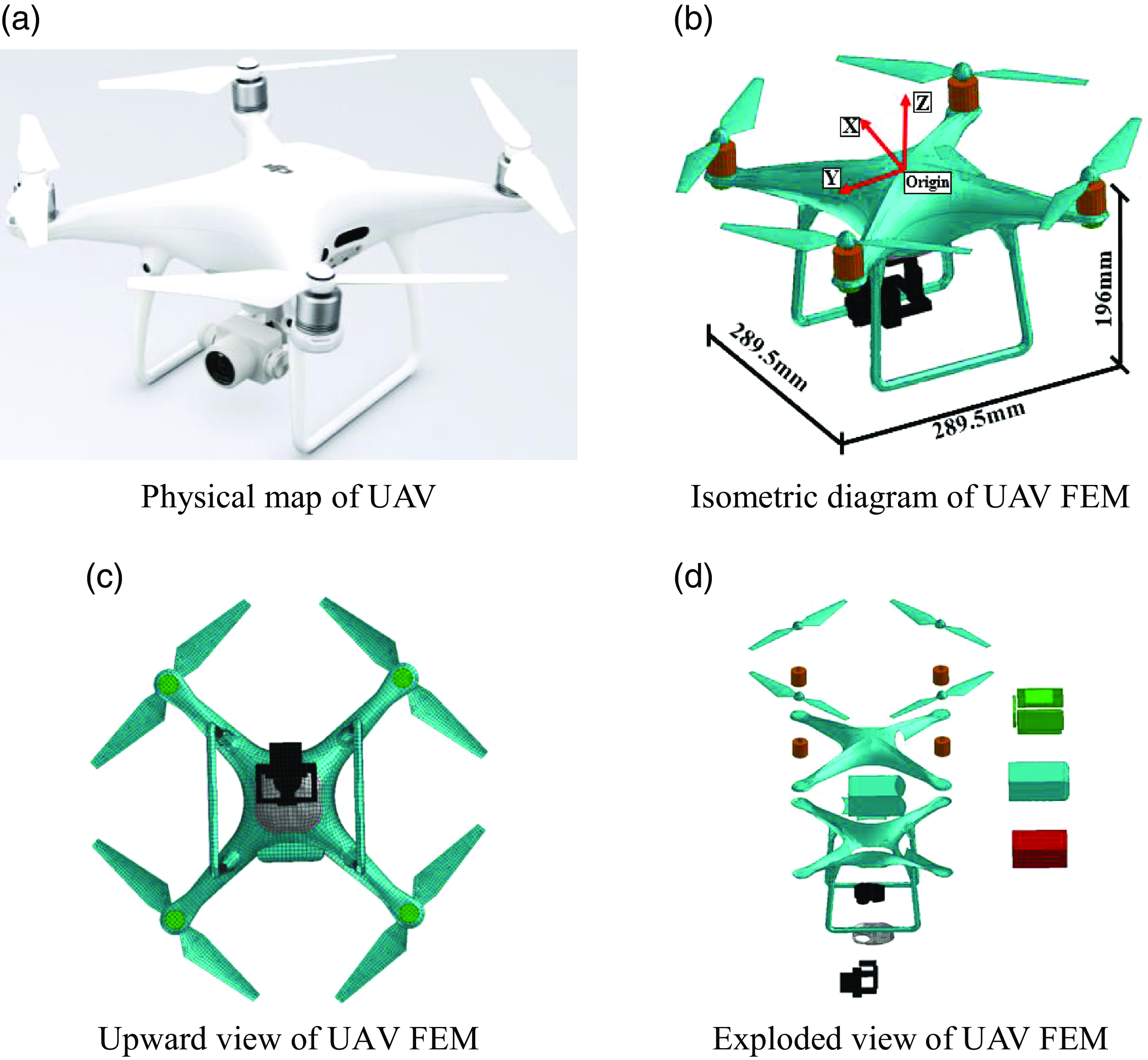
Figure 1. Physical map and of finite element model UAV.
The dynamic mechanical behaviour of the Li-Po battery is characterised by using a compressible foam model, and some mechanical performance parameters obtained from the results by Sahraei are listed in Table 3 (see Refs (Reference Sahraei, Meier and Wierzbicki28, Reference Sahraei, Hill and Wierzbicki29)). The elastic-plastic material model is applied to establish the dynamic law of the fuselage shell and blade of the UAV, and the material parameters of the PC are listed in Table 4 (see Ref. (Reference Yin and Wang30)). The circuit board of the UAV is assumed to be made of a glass-epoxy composite whose performance parameters are measured by K. Ravi-Chandar and S. Satapathy (see Ref. (Reference Ravi-chandar and Satapathy31)) and are displayed in Table 5.
For the connection of UAV components in the simulation model, all parts are considered to be linked with the TIE constraint and co-nodes, where the connection strength of the TIE constraint is initially set to be a reasonable assumption and then revised according to the test results.
2.2 FE model of aircraft windshield
The main windshield of a commercial aircraft is made of toughened inorganic glass, and it is in a balanced state of internal stress, which means that it cannot be installed by riveting or screwing. The windshield consisted of three layers of glass and two layers of interlayer film, in which the three layers of glass are chemically inorganic, and the two layers of interlayer film are organic materials. The windshield periphery is covered with silicone rubber as shown in Fig. 2(a) and (b), where L1 is the first layer of glass (i.e. the outer layer of the non-bearing structure) with a thickness of 3 mm; L2 is the second layer of glass (i.e. the intermediate bearing structure layer); and L3 is the third layer of glass (i.e. the inner bearing structure layer) with thicknesses of 8 and 6 mm, respectively. Polyurethane (PU) and polyvinyl putyrals (PVB) are adhesive layers with thicknesses of 4 and 1.5 mm, respectively. Each layer of the windshield module is discretised by solid units with eight-node reduced integral elements. The single-element side length is approximately 7 mm, and the total number of elements is about 267,000, which is shown in Fig. 2(c).
Table 1. Material and weight distribution of main components of UAV

Table 2. Johnson–Cook constitutive model parameters

Table 3. Mechanical performance parameters of Li-Po battery

Table 4. Mechanical performance parameters of PC material

Table 5. Mechanical performance parameters of glass-epoxy resin composite material

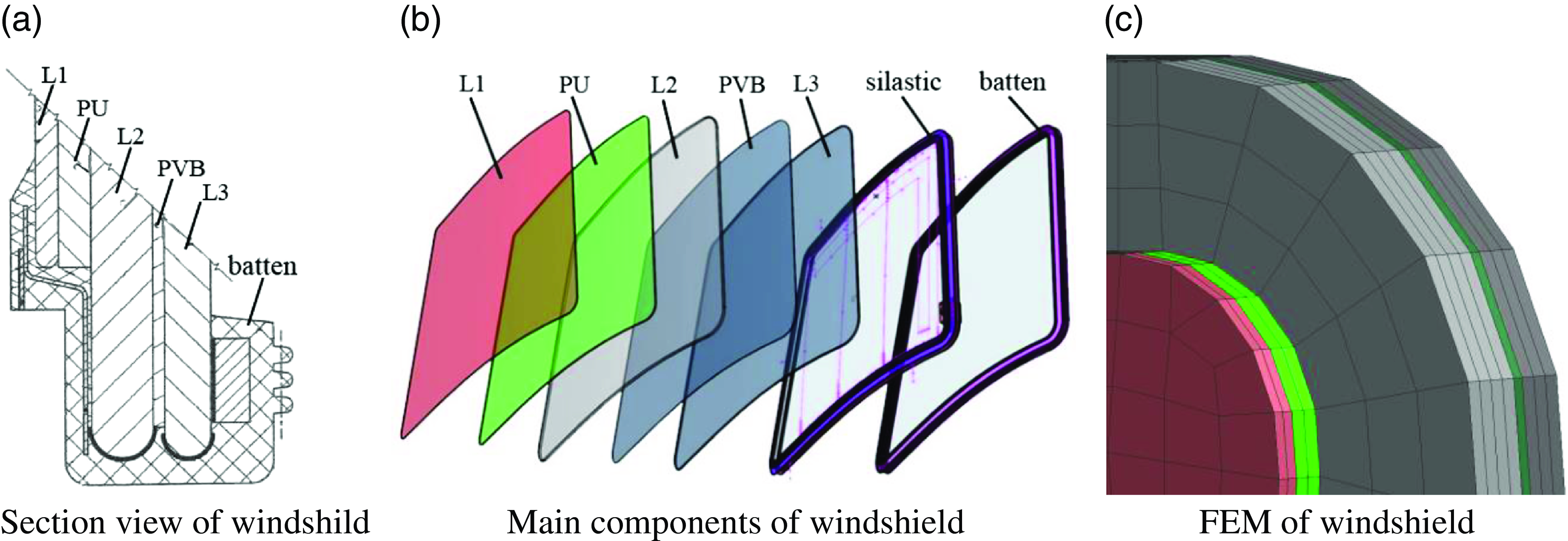
Figure 2. Model of windshield.
To simulate the more actual collision conditions between the windshield and UAV, a full-size nose of a commercial aircraft, including the main windshield components, is established as shown in Fig. 3, and the modeling details of the nose metal structure, including the windshield frame support structure, can be found in our previous study [Reference Lu, Liu, Zhang, Li and Zuo32]. In the FE model, the periphery of the windshield is elastically connected to the frame through silicone beads, and the windshield glass, PU and PVB are bonded by using adhesive films. The bottom structure of the nose is constrained to six degrees of freedom. According to the test results, the connection strength and failure parameters between windshield components is properly adjusted.

Figure 3. FEM of a full-scale nose of a commercial aircraft.
According to the mechanical properties of aviation inorganic glass from Ref. (Reference Wang, Zhang, Wang and Wang33), the stress-strain curve of glass consists of elastic and failure stages. When the stress increases to a certain level, the glass specimen breaks suddenly and the stress drops sharply, which clearly displays the brittle feature of the glass specimen. Therefore, an elastic–plastic constitutive model of the windshield is selected to describe its dynamic behaviour, and the plastic strain of the failure deletion is setting to 0.001. The yield strength is corrected through the analysis of variance of strain measurement values of simulation and test and is determined by minimisation. Similarly, the elastic–plastic constitutive model is used to approximatively describe the dynamic behaviour of PU and PVB with stress-strain curves (see Ref. (Reference Zhang, Zhang, Yao and Zang34)). The performance parameters of the various windshield materials are listed in Table 6.
Table 6. Mechanical performance parameters of windshield materials

2.3 Collision condition between UAV and aircraft windshield
Based on the clauses in FAR 25.571 (e) (1) and CCAR 25.571 (e) (1), the velocity in bird-strike test is approximately 151 m/s. To study whether the windshield that had been certified to be airworthy and safe anti-bird strike can resist the impact of UAV with similar weight to bird, the impact velocity same to bird-strike test that superimposes the relative velocities of the aircraft (about 131 m/s) and the UAV (about 20 m/s), is selected. The velocity of aircraft (about 131 m/s) corresponds to the height below 3,000 meters mean sea level (MSL) to conform the FAR 91.117 and CCAR 91.117. According to the design criteria of the windshield supplier and operation standards of the aircraft manufacturer, the outer glass, which is a non-bearing component, is allowed to crack to some extent. However, it could not affect the flight field of vision. Neither the intermediate nor the inner glass is allowed to crack because of their bearing functions. Particularly, they would cause damage to the equipment and personnel in the cockpit. Therefore, the damage degree of aircraft windshield from slight to severe is divided into three categories, namely, the outer glass breaking, intermediate glass rupturing and inner glass cracking, which represents the safe, dangerous and disastrous status of aircraft, respectively.
3.0 Brief description of collision testing
3.1 Testing preparation
The purpose of the collision testing is to verify the safety of aircraft windshields, that have been certified as qualified by bird-strike tests, impacted by UAV with different postures. There are the same impact velocity, uniform impact posotion of windshield centre and close projectile weight in the process of UAV impact and bird strike. The testing device consists of the whole UAV hung in the portal frame by a Kevlar rope, rocket sled composed of a rocket booster, two guide rails, water brake, nose including main windshield and high-speed cameras fixed on the ground and vehicle-mounted. A schematic of the testing equipment layout is shown in Fig. 4.
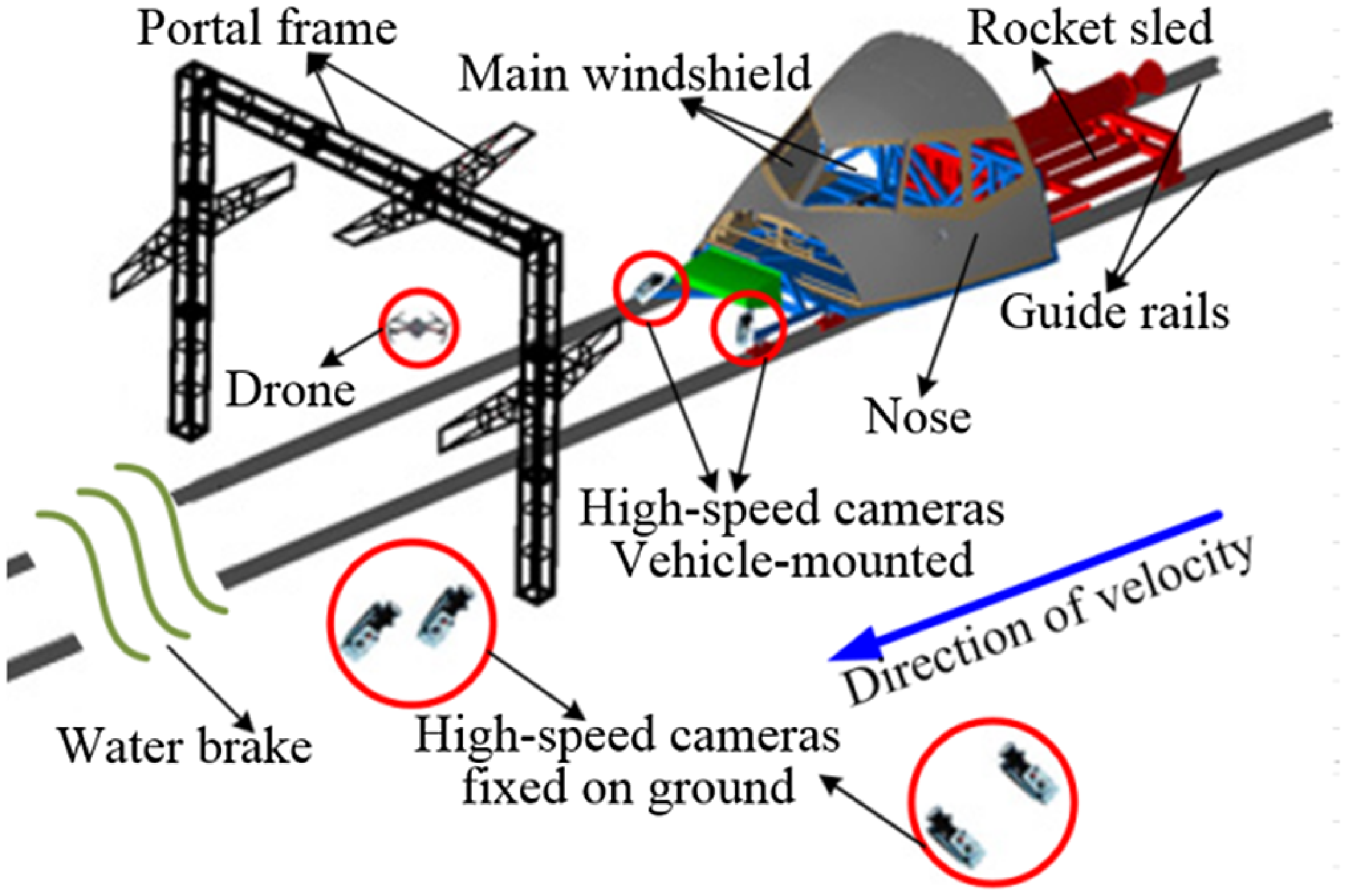
Figure 4. Diagram of collision testing.
The nose test piece is moved towards the UAV under the push of a rocket sled booster. By adjusting the distance between the starting position of the nose and the positioning point of the UAV, the velocity of the nose colliding with the UAV can be controlled. Compared with the testing conducted based on the principle of an air cannon in other studies, there are a few advantages that the collision scene is simulated completely and truly, and the UAV is still in normal working condition at the moment of collision.
3.2 Testing result and FE model validation
As shown in Fig. 5, the middle positions of the left and right windshields of the aircraft are impacted by the UAV with horizontal flying posture, pitch at 45°, and yaw at -24.4°, which have been verified to be the most severe cases in all collision tests. The measured velocities of aircraft nose during the collision are 150.7 and 154.8 m/s respectively, whose precision are satisfactory. Collision testing and simulation results shows that only the first layer of glass on the left windshield is damaged, and all three layers of glass on the right windshield are cracked. The adhesive layers of PU and PVB are not broken but slightly deformed. This reveals that the flying posture of the UAV at high speed has a significant influence on the impact damage to the windshield. Owing to space limitations, a detailed comparative analysis of the damage size, measurement strain and UAV state at typical moments in testing and simulation are omited here and can be achieved in Ref. (Reference Lu, Liu, Li, Zhang and Zuo21). The testing results also fairly confirm the rationality of the simulation model, based on which the effect analysis of collision damage between the UAV and windshield in more possible cases, such as controllable normal flight and uncontrolled crashing cases, will be conducted by using the FE model.
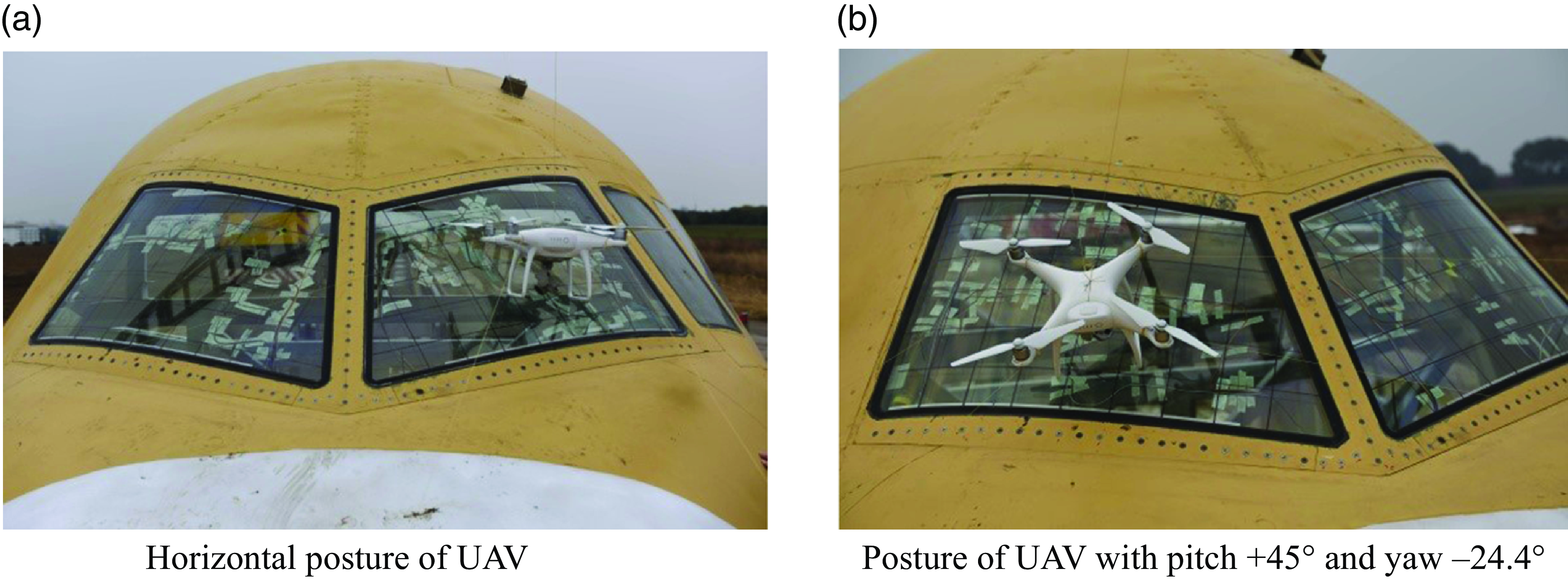
Figure 5. Map of different postures of UAV impacting windshield.
4.0 Damage analysis of windshield
4.1 Simulation cases and results
The middle section of the main windshield of the aircraft is a weaker area, which has been partially verified previously (see Ref. (Reference Lu, Liu, Li, Zhang and Zuo21)). In this section, the damage effect on collision between the windshield and light UAV with different postures is analysed, and the six impact postures of the UAV shown in Fig. 6 are considered. The difference between Case 2 and Case 3 lies in the belly of the UAV perpendicular and parallel to the outside surface of the windshield, which would lead to two rigid motors, and the polymeric buffering frame of the UAV to first impact the windshield, respectively. In Case 4 and Case 5, the motors and arms of the UAV directly impacted the windshield, respectively. However, the sections of the windshield impacted by the camera and battery of the UAV and the sequence of components impacting the windshield are different. The belly of the UAV in Case 6 is almost completely parallel to the tangent plane of the windshield. Representative diagrams of UAV with different postures impacting the windshield of the aircraft are shown in Fig. 7, where the centre of gravity of the UAV is aimed at the impact point of the windshield. The simulation velocities in all the above cases are 151 m/s, which is identical to the desirable testing velocity.
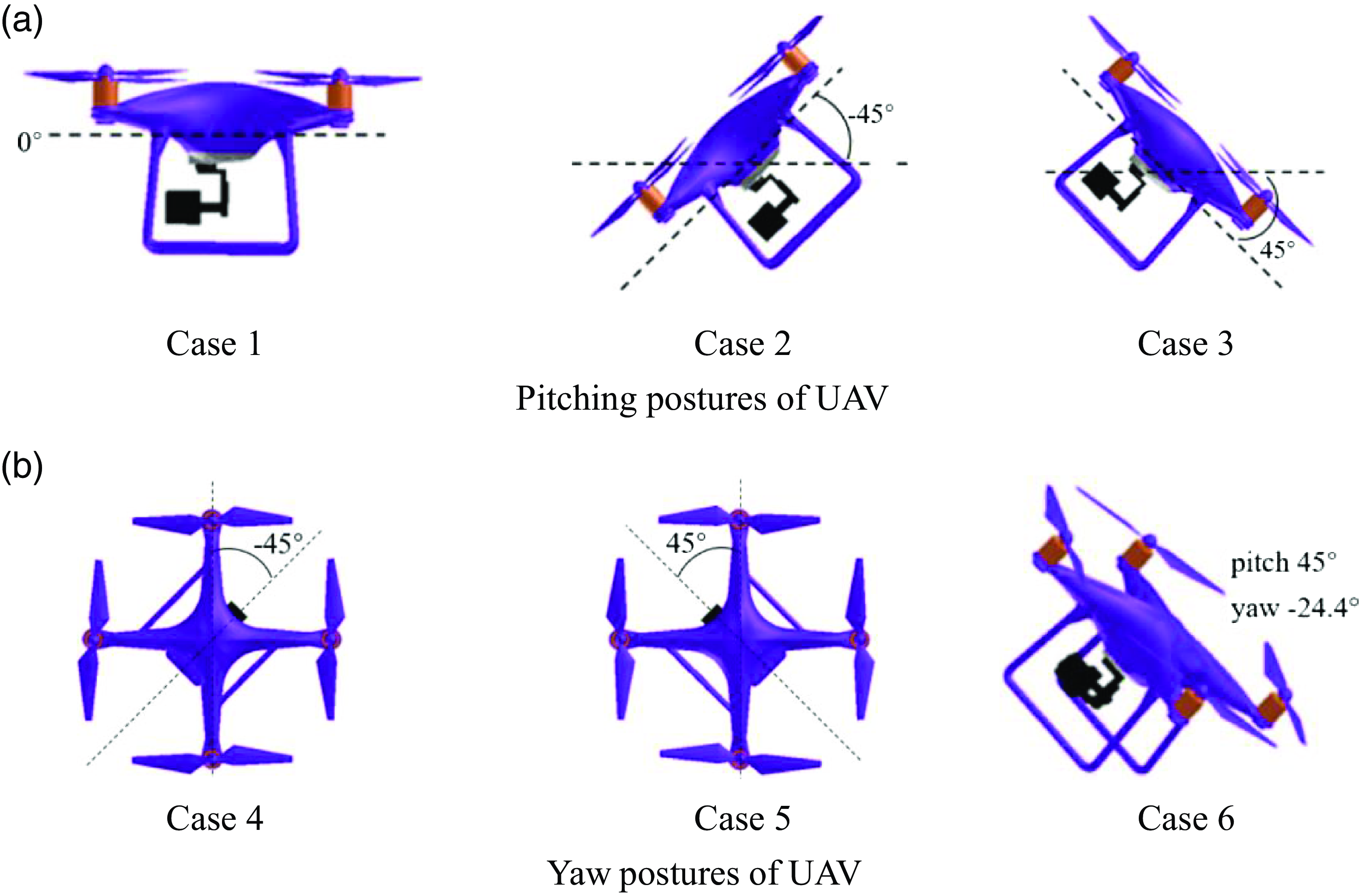
Figure 6. Different impact postures of UAV.

Figure 7. Schematic diagram of UAV impacting windshield with different postures.
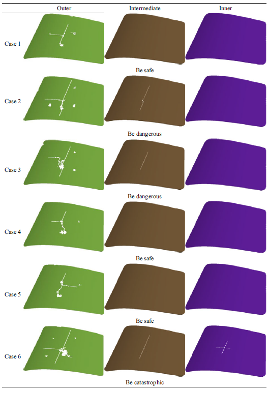
According to the above impact cases, the final simulation results are as follows: only the outer layer glass of the windshield is damaged in Cases 1, 4, and 5, and the damage degrees of Cases 4 and 5 are similar, which meets the requirements of flight safety. Both the outer and intermediate layers glass of the windshield are damaged in Cases 2 and 3, and the damage range is somewhat consistent, which does’t meet airworthiness requirements and poses a great danger to flight safety. All three layers glass of the windshield are damaged in Case 6, which is most severe damage and will have a disastrous effect on flight safety. The damage appearance of each layer glass of the windshield in the above six cases is listed in Table 7. Cases 1 and 6 are the portions of all cases in collision testing, and the damage results of the simulation and testing demonstrated in Ref. (Reference Lu, Liu, Li, Zhang and Zuo21) are qualitatively consistent.
Table 7. Damage appearance of aircraft windshield collided with UAV in six cases
4.2 Behaviour analysis of collision damage
Based on the simulation results and damage degree classification in Table 7, the damage bahaviour in typical cases in the collision process is analysed in detail.
The curves of the contact force and energy of the windshield during impacting in Case 1 are shown in Figs. 8 and 9, respectively. The battery and camera of the UAV impact the windshield at about 0.6 ms after beginning and damage is instantly initiated on the outer layer glass. Subsequently, the contact force increases sharply, and the internal energy of the outer layer glass and PU layer increases dramatically synchronously. However, the outer glass layer continues to be impacted by the UAV components when the PU layer reaches a low steady-state energy, which leads to the internal energy of the outer layer reaching a maximum after approximately 2.48 ms. Subsequently, its damage doesn’t continue to expand. The impact processes in Cases 4 and 5 are similar to those in Case 1.

Figure 8. Contact force curve in course of impacting between UAV and windshield in Case 1.

Figure 9. Energy curves of the front three windshield parts in course of impacting in Case 1.
The curves of the contact force and energy of the windshield during impacting in Case 2 are shown in Figs. 10 and 11, respectively. One of the motors of the UAV begins to impact the windshield surface approximately 0.6 ms after launching, and the internal energy and contact force of the outer layer that is broken instantly increased rapidly. The contact force reaches the maximum after 1.96 ms and then the intermediate layer glass begins to crack, during which the energies of the PU layer and outer layer glass increases almost synchronously and the energy of the intermediate layer glass increases because of energy absorption and deformation of the PU layer. Therefore, the damage of the intermediate layer glass propagates although the contact force decreases after 1.96 ms. When the internal energy of the intermediate layer glass reaches a maximum after 2.6 ms, the crack expansion stops, and the energy gradually decreases and tends to be stable. The energy of the PU layer fluctuates slightly because of the slow increase in the energy of the outer glass layer after 2.6 ms. When the energy of the outer glass layer reaches a maximum after 3.14 ms, the damage stops expanding, and the energy of the PU layer stabilises. After that, the energy of the outer glass layer drops rapidly and then stabilises almost as synchronously as that of the intermediate glass layer. The impact process in Case 3 is similar to that in Case 2.
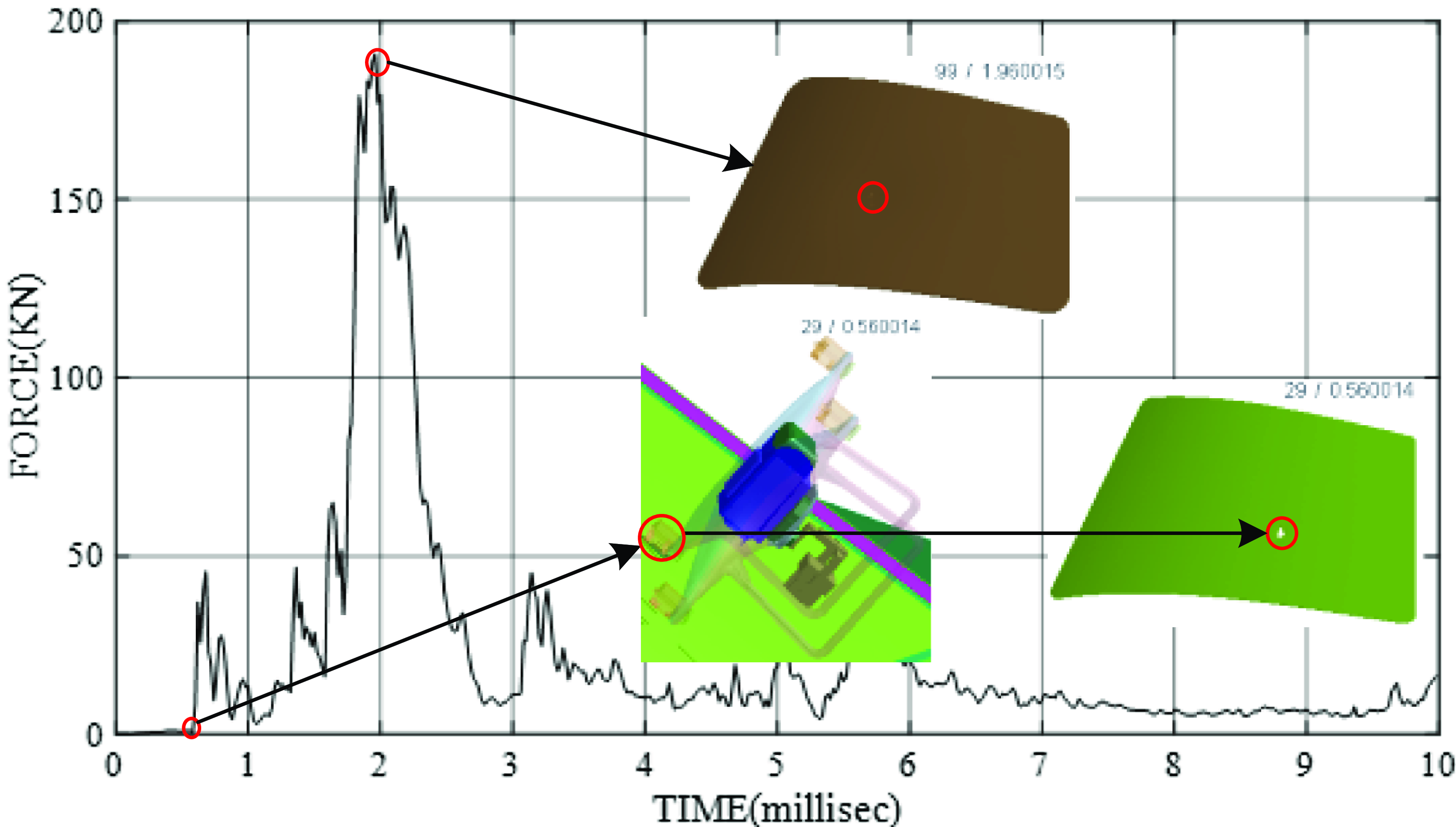
Figure 10. Contact force curve in course of impacting between UAV and windshield in Case 2.

Figure 11. Energy curves of the front three windshield parts in course of impacting in Case 2.
The curves of the contact force and energy of the windshield during impact in Case 6 are shown in Figs. 12 and 13, respectively. The camera of the UAV impacts the windshield at 0.4 ms after starting and both the outer and intermediate layer glass undergo crack initiation almost simultaneously. Since then, the energies of the outer glass and PU layers increases sharply. The PU layer can reach the maximum internal energy close to that of the outer layer glass owing to its large thickness and excellent absorption capability. The energy is then transferred to the intermediate layer glass, PVB layer and inner layer glass. However, the PVB layer, which mainly plays a bonding role to prevent broken glasses from falling off, is thinner and weaker in energy absorption ability, and the high energy absorbed by PU is directly transmitted to the inner layer glass after the intermediate layer glass broke, which results in inner layer glass cracking. After approximately 2 ms, the internal energy of the three layers glass almost synchronously reaches the maximum as far as the damage severity.
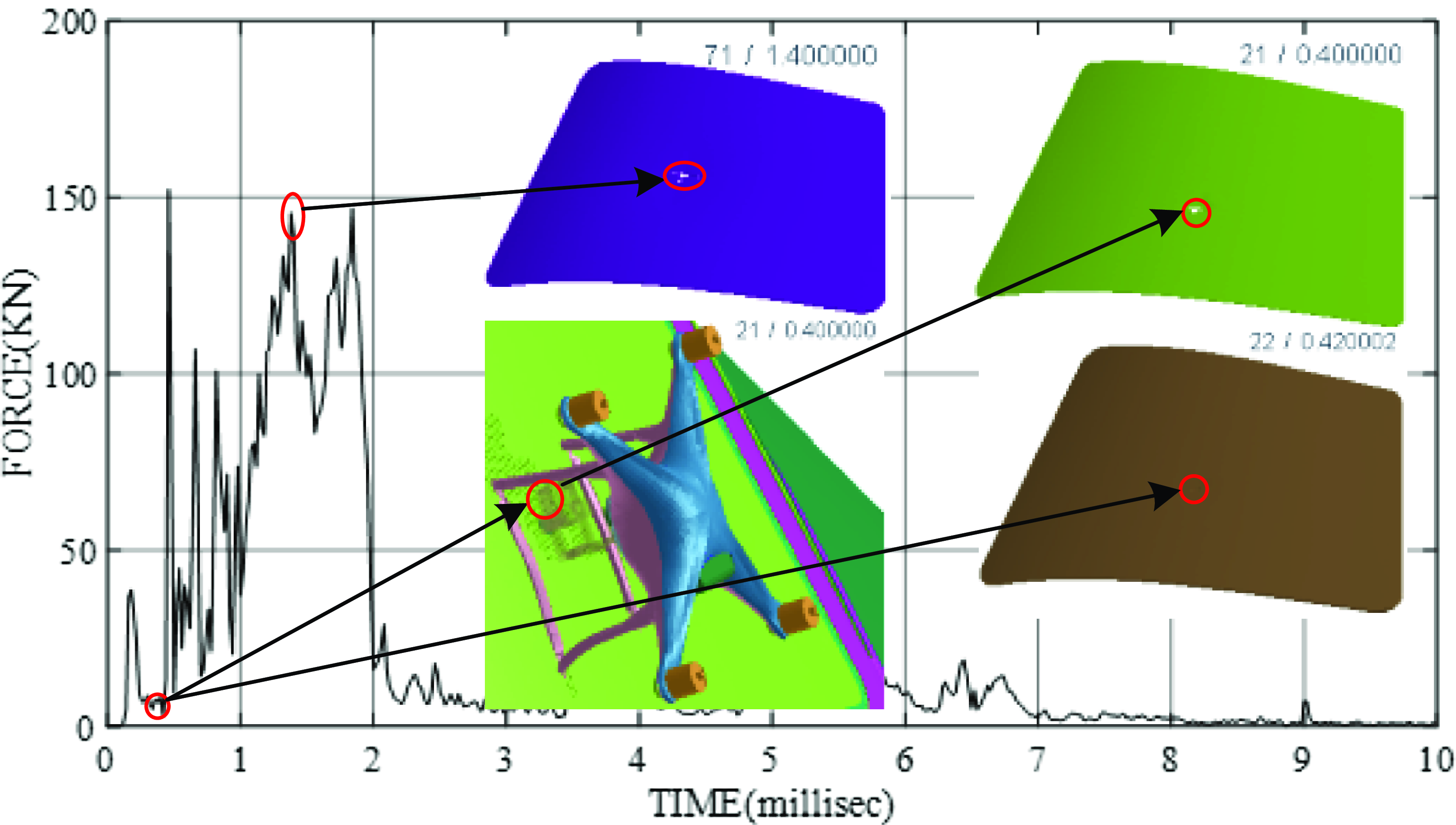
Figure 12. Contact force curve in course of impacting between UAV and windshield in Case 6.

Figure 13. Energy curves of the front three windshield parts in course of impacting in Case 6.
The curves of the internal energy and contact force of each windshield component for the above six cases are shown in Figs. 14–17.

Figure 14. Energy curves of the outer windshield in course of impacting in six cases.
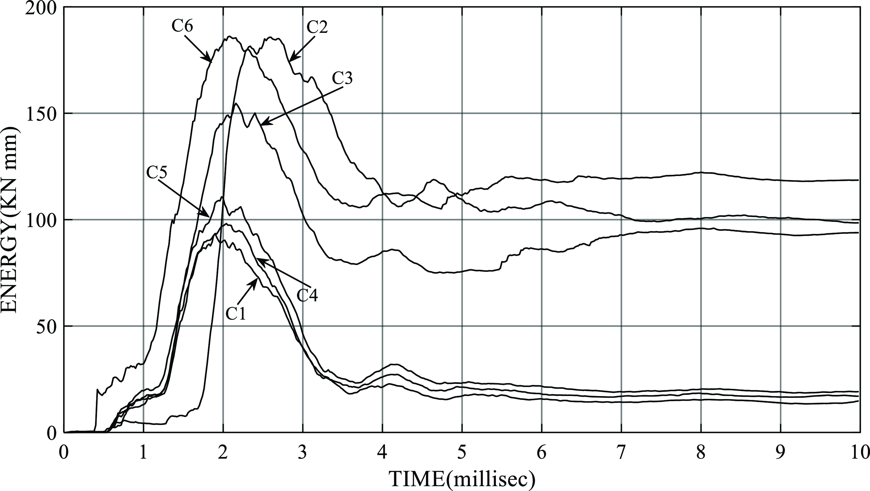
Figure 15. Energy curves of the intermediate windshield in course of impacting in six cases.
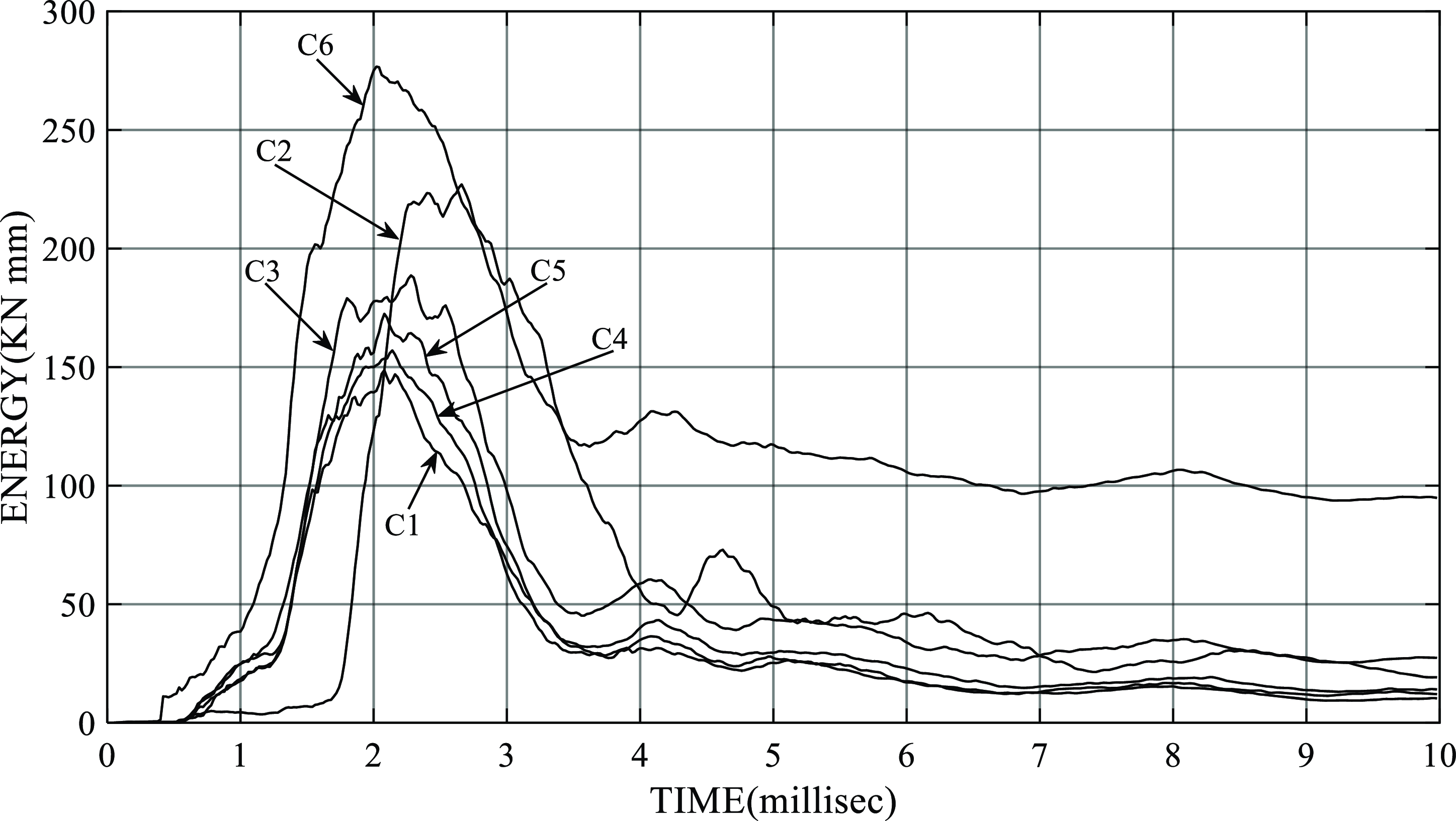
Figure 16. Energy curves of the inner windshield in course of impacting in six cases.
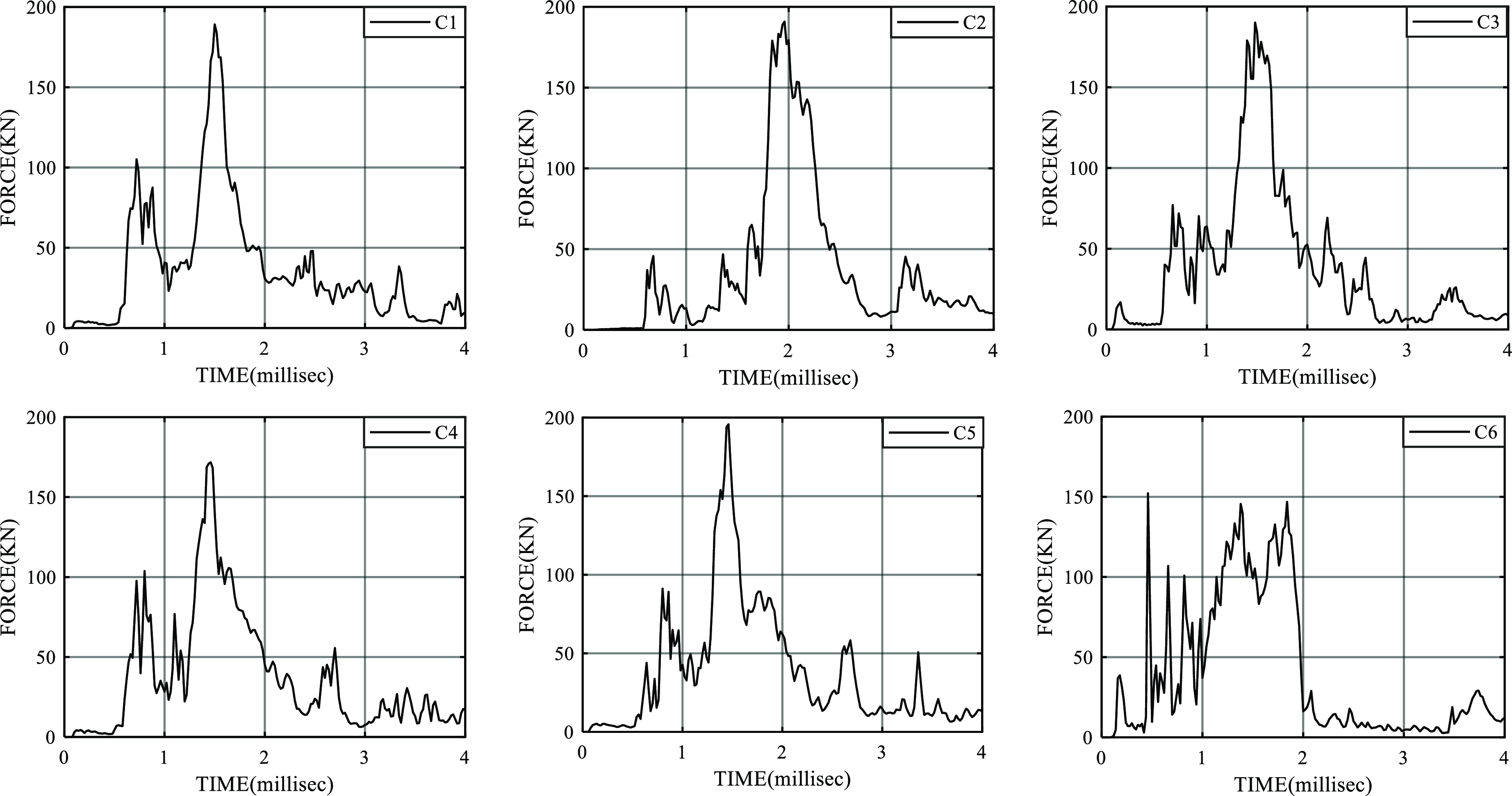
Figure 17. Contact force curve in course of impacting between UAV and windshield in six cases.
From Fig. 14, it is clear that the maximum and steady-state energies of the outer layer glass in Cases 1, 4 and 5 are smaller than those in Cases 2, 3 and 6, which indicates that the damage severity of the windshield impacted by the UAV with pitching postures is more significant than that with yawing postures and it will be more serious for the windshield impacted by the UAV with a combination of pitching and yawing postures. The reason for this is that large-mass batteries and camera components of UAV with pitching posture impact the windshield earlier than others do, whereas small-mass motor assembly with yawing posture impacts the windshield earlier than others do. From the viewpoint of the maximum energy, the order of the six cases is as follows: C1<C4<C5<C2
![]() $\approx$
C3<C6, which is nearly consistent with the order of damage severity of the outer layer glass of the six cases shown in Table 7.
$\approx$
C3<C6, which is nearly consistent with the order of damage severity of the outer layer glass of the six cases shown in Table 7.
The energy of the intermediate layer glass in Cases 2, 3 and 6 is clearly higher than that in Cases 1, 4 and 5, as shown in in Fig. 15, which may qualitatively explain the integrity of the intermediate layer glass in Cases 1, 4 and 5 and breakdown in Cases 2, 3 and 6. The maximum energy in Cases 2, 3 and 6 is in the order of C3<C2
![]() $\approx$
C6, which corresponds to the damage tendency of the intermediate layer glass in the three cases described in Table 7. The damage severity of the intermediate layer glass in the six cases also illustrates that the pitching posture of the UAV would cause more susceptive damage to the windshield.
$\approx$
C6, which corresponds to the damage tendency of the intermediate layer glass in the three cases described in Table 7. The damage severity of the intermediate layer glass in the six cases also illustrates that the pitching posture of the UAV would cause more susceptive damage to the windshield.
The maximum energy of the inner layer glass in Case 6 is larger than that in other cases as shown in Fig. 16, which is in agreement with the fact that it is only in Case 6 that the inner layer glass can be broken. Combining Fig. 6, 14 and 15, the difference in the maximum energy of every adjacent layer glass impacted by the UAV with pitching postures such as in Cases 2, 3 and 6, gradually increases, which indicates that the effect of different impact postures of the UAV on the damage of the inner layer glass is more significant although the impact kinetic energies of the UAV are the same.
As shown in Fig. 17, the maximum contact force in each case is similar and there are many impact force peaks during collision, which is mainly caused by the discrete layout of all large-mass components of the UAV. Therefore, owing to the dispersion of the space configuration of the UAV, the contact force during collision are not suitable for one of the criteria for judging the damage severity.
5.0 Conclusions and further discussions
The effects on damage to aircraft windshields impacted by typical light UAV with different postures are studied based on simulation models verified qualitatively by collision testing results between the entire UAV and full-scale aircraft nose. The following conclusions are drawn:
-
(1) The UAV flight posture has a significant effect on windshield damage under high-speed collision conditions. Owing to the long-span configuration of three types of concentrated-density components of UAV, namely, the battery, camera and motor, with their weight closely accounting for two-thirds of the total weight of the UAV, it would cause serious damage to the windshield impacted directly or sequentially by large mass components of UAV with a spacial posture.
-
(2) The high-hardness characteristics and large-density attributes of the three types of UAV components are the main factors that lead to cracks in one or more layers glass. The internal energy absorbed by the windshields rather than the impact contact force has a positive correlation with the damage severity and could represent the degree of damage of the windshield.
-
(3) The windshield airworthiness-certified through bird-strike tests would no longer be airworthy when it is impacted by the UAV close in quality to the bird with a special posture, such as pitching 45° and yawing −24.4° under the same conditions as the bird-strike test.
-
(4) The authors did not consider the different impact postures of drones in Ref. (Reference Lu, Liu, Li, Zhang and Zuo21), which acquired the damage degree lighter than that in this paper. However, the damage to aircraft windshields caused by UAV impact with special posture is far more serious than that caused by bird strikes in similar conditions. With the increasing application of UAVs, it may introduce great safety risks to the operation of manned aircraft if the design standards of UAV are not regulated and their operation behaviour is not supervised.
This research provides rational cognition and technical pre-research support for emerging and increasingly frequent potential hazards in air transport practice. In view of the high economic cost and long period of collision tests between the entire UAV and full-scale aircraft nose, various simulation cases will be conducted based on typical tests in the future. Therefore, FE modeling in detail on windshield damage mechanisms should be further developed, such as the effect of the glass layer thickness on the damage propagation of the windshield. In addition, the aerodynamic coupling transactions of the UAV and aircraft during collision, influence on damage to the windshield impacted by UAV in high- or low-temperature environments, secondary damage caused by UAV battery explosions, determination of critical cases under various damage classifications, and the establishment of a convincing and general UAV model are also important research considerations in the future.
Acknowledgements
It is supported by the Fundamental Research Funds for the Central Universities, NO.NS2022066. We would like to express our sincere gratitude to the Shanghai Aircraft Design and Research Institute, Northwestern Polytechnical University, and DJ-Innovations for their valuable help in modeling aircraft windshield and UAV. Moreover, the authors appreciate the Civil Aviation Airworthiness Certification Center of China for providing funding support, good ideas, and directional suggestions.


