Introduction
To formulate the failure criterion of a solid it is important to know the elastic strain energy E of the solid containing cracks and the crack extension force G, which is equal to the negative of the derivative of the elastic energy with respect to crack length. In considering stress fields due to cracks in fracture mechanics, it is customary to distinguish the three cases shown in Figure 1 (Reference Bilby and EshelbyBilby and Eshelby, 1968):


Fig. 1. The three modes of crack propagation in a solid.
The elastic stress field and the energy of such cracks in terms of externally applied stress fields have been derived by several workers: Reference StrohStroh (1958) has formally treated the problem for a general anisotropic medium using the method of Fourier transforms and dual integral equations, and Reference Barnett and AsaroBarnett and Asaro (1972) have used the method of double-ended pile-up of continuously distributed, infinitesimal dislocations, to solve the problem of a slit-like crack in an arbitrarily anisotropic elastic medium under uniform stress. Reference YooYoo (1979, 1980) has used these solutions to calculate the elastic energy of slit cracks in hexagonal crystals and to develop a dislocation model for twinning and fracture in metals of hexagonal close-packed structure.
In this paper the above solutions are used for ice having a hexagonal structure to calculate the ratios of the critical stresses for crack initiation on the basal and prismatic planes, as well as the ratios of the surface energies associated with cracks. The ratios of the critical stresses for basal cleavage and {1012} twin and for prismatic cleavage and {1011} twin are also calculated. From these ratios a prediction is made of the tendency for twinning and cleavage in ice.
Background of the calculations
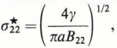
Reference YooYoo (1979, 1980) derived the equations for critical stresses for crack and twin initiation from the Reference Bilby and EshelbyBilby and Eshelby (1968) theory. By considering a crack as a double-ended pile-up of dislocations, the critical stresses for formation of the three modes of cracks shown in Figure 1 are as follows (Reference YooYoo, 1979): for a Mode I crack under a uniaxial stress σ 22 :

for a Mode II crack under a shear stress σ 21 :

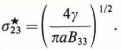
and for a Mode III crack under a shear stress σ 23:

The subscripts 1, 2, and 3 correspond to the cartesian coordinates x, y, and z. The elastic compliance factor Bij is the symmetrical second-rank tensor defined by Reference StrohStroh (1958), depending on the elastic constants Cij and crack orientation; i, j take any of the values 1, 2, and 3; 2a is the length of the crack. The surface energy γ associated with the crack plane x 2 =0, is given by (Reference YooYoo, 1979)

where ![]() is the transformed elastic stiffness constant with respect to the crack plane (hkl) having interplanar spacing d.
is the transformed elastic stiffness constant with respect to the crack plane (hkl) having interplanar spacing d.
For an orthotropic medium (a solid with three mutually perpendicular planes of symmetry) Bij
s are the inverse of the energy factors Kij
for a dislocation, and expressions for these in terms of standard elastic constants have been obtained by Reference Savin, Savin, Chernov and StrokovaSavin and others (1976). For a dislocation lying on the basal plane with Burgers vector ![]() , they show that
, they show that


and

where

From Equation (4), the ratio of the surface energies associated with cracks in the basal and prismatic planes is given by (Reference YooYoo, 1979)

where ![]() for {1010} planes and 2 for {1020} planes, c and a are the lattice parameters for the hexagonal lattice, in the present case of ice. Equations (1) to (9) can be used to give the ratio of the critical stress for crack extension in the basal and prismatic planes as (Reference YooYoo, 1979)
for {1010} planes and 2 for {1020} planes, c and a are the lattice parameters for the hexagonal lattice, in the present case of ice. Equations (1) to (9) can be used to give the ratio of the critical stress for crack extension in the basal and prismatic planes as (Reference YooYoo, 1979)


The subscripts ∥ and ⊥ indicate whether crack extension occurs parallel or perpendicular to the c-axis.
To calculate the critical stress for twin nucleation, Reference Yoo, Haasen, Gerold and KostorzYoo (1980) treats a micro-twin as a slit crack, for simplicity, neglecting the finite thickness of the twin and the welded boundary conditions for twin interfaces. Although far from rigorous, this treatment enables one to estimate the propensity for twin nucleation versus crack propagation. Two cases are considered: (a) basal cleavage versus {1012} twin, and (b) prismatic cleavage versus {1011>} twin.
From Equation (1) the critical stress for crack extension on the basal plane can be written as

where f c is the total inelastic resistance to crack extension; this includes both the lattice resistance to dislocation motion and the surface energy associated with the crack forces. Considering a micro-twin as a Mode II slit crack, the condition for twin extension from the Bilby–Eshelby theory, is given by Reference Yoo, Haasen, Gerold and KostorzYoo (1980) as

where ![]() denotes the stress components with respect to the twin axis x′i
inclined at an angle θ with the original coordinate axis xi
, and f
t is the total inelastic resistance to twin extension.
denotes the stress components with respect to the twin axis x′i
inclined at an angle θ with the original coordinate axis xi
, and f
t is the total inelastic resistance to twin extension.
For a uniaxial stress σ22,

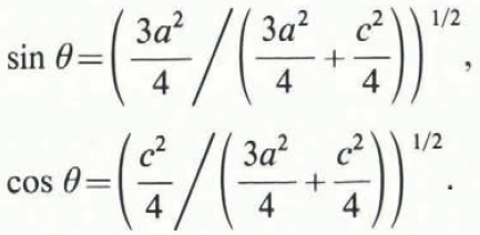
For a {1012} ‹1012› twin, which is the most common type in hexagonal close-packed crystals (see Fig. 2a),

Using Equations (14) and (15) in (13), the critical stress ![]() for twin propagation is given by
for twin propagation is given by

where β = c/a. For the isotropic case, B′ 12 = 0 and B′ 11 = B′22; hence, from Equations (12) and (16), the ratio of the critical stresses for basal cleavage and {1012} ‹1011› twin is

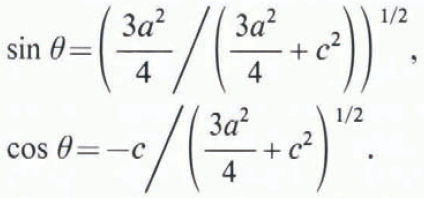
Next, considering the ratio of the critical stresses for prismatic cleavage and a {


Using the conditions of Equations (18) and (14) in (13), the critical stress ![]() for twin propagation can be derived as (Reference Yoo, Haasen, Gerold and KostorzYoo, 1980)
for twin propagation can be derived as (Reference Yoo, Haasen, Gerold and KostorzYoo, 1980)

Analogous to Equation (12), the critical normal stress for extension of a Mode I crack on the {


From Equations (19) and (20), and assuming B′ 12 = 0 for the isotropic case, the ratio of the critical stresses for prismatic cleavage and a {


Fig. 2. Geometry of a {1012} ‹ 1011› twin (a), and a{1011} ‹101 2 › twin (b).
Equations (9) to (11), (17), and (21) may now be used to calculate the surface energies of cracks in the basal and prism planes, and the ratios of the critical stresses for crack formation and twinning at various temperatures in ice. For a hexagonal lattice, the non-zero elastic constants are
The temperature dependence of these constants for ice has been given by Reference DantlDantl (1968), and the temperature dependence of the lattice parameters c and a for ice by Reference LonsdaleLonsdale (1958).
Results and discussions
Values of the elastic constants Cij and the lattice parameters c and a calculated for various temperatures from Reference DantlDantl’s (1968) and Reference LonsdaleLonsdale’s (1958) equations are shown in Table I. Figure 3a and b shows the variation of Cij, c, a, and c/a with temperature. Using these values in Equations (9) to (11), the ratios of surface energies (γ b/γ p) and the critical stresses for crack formation (σ b/σ p) in the basal and prismatic planes were calculated. Assuming f c = f t (f c and f t are the lattice resistance to crack and twin propagation, and these include surface energies) in Equations (17) and (21), the ratios of the critical stresses for crack and twin propagation, namely σ c/ σ t, were also calculated. All these values are shown in Table II. The value of γb/γp{1010} is about 1.03 showing that the probability or ease of crack formation is almost the same in the basal and {1010} prismatic planes. The ratio of the surface energies in the basal and the {1120} planes, however, is about 0.89, indicating that crack formation in the {1120} plane is more difficult than that in the basal or {1010} planes. The value of the ratio σ b/ σ p of critical stresses for crack extension in the basal and prismatic planes is almost equal to 1 for all temperatures, for cracks extending parallel or perpendicular to the c-axis.
Table I. Values of Elastic Constants Cij (units: 103 MPa) and lattice parameters c and a (units: 10–10 m)

Table II. Values of Energy Factors Kij = 1/Bij (units: 103 MPa) and ratios of surface energy and critical stresses for crack and twin propagation


Fig. 3. (a) Variation of elastic constants Cij of ice with temperature, (b). Variation of lattice parameters c and a with temperature.
These results suggest that, under a uniaxial stress, cracks could propagate in ice with equal ease, either along the basal or along the prism planes, although the probability of their occurrence on the basal and the {1010} planes is slightly more than that along the {1120} plane. (In this paper, crack propagation along planes at other angles to the c-axis, such as the pyramidal planes, has not been considered.) This coincides with observations made by Reference GoldGold (1972), who carried out detailed and extensive studies on various aspects of cracking activity in ice. He found that in polycrystalline ice subjected to uniaxial compressive stress at temperatures between –5 and –30°C, about 25% of the observed cracks are along the grain boundaries, 42% in the basal plane, and 20% perpendicular to the basal plane; the rest were irregular. He also observed that the most probable direction of crack propagation is parallel to the compressive stress direction. Reference Parameswaran and JonesParameswaran and Jones (1975) tested single-crystal and polycrystalline ice at – 196°C (77 K) under uniaxial compression. No particular orientation dependence was observed for crack propagation. The modes of failure were in general: (a) axial cleavage with one or more major cracks splitting the sample along the loading direction, and (b) cataclasis or general internal crumbling by formation of multiple cracks. The cracks did not follow any particular pattern or crystallographic plane.
Considering the ratio σ c /σ t of the critical stress for basal cleavage and {1012} twin, or prismatic cleavage and {1011} twin, it may be seen from Table II that σ c/σ t has values of 0.5 and 0.41 respectively for the two cases. This shows that mechanical twinning is almost impossible in ice, because the critical stress required for twin initiation is twice that for cleavage crack propagation. This explains why no one so far has observed mechanical twinning in ice crystals, although several workers have studied the deformation behaviour of ice under various conditions. This does not preclude the existence of growth twins in ice. The peculiar shapes of snow crystals (grown under both natural and artificial conditions) observed by investigators such as Reference Bentley and HumphreysBentley and Humphreys (1931), Reference NakayaNakaya (1954), Reference KikuchiKikuchi (1970), Reference Kikuchi and HoganKikuchi and Hogan (1976), and Reference YamashitaYamashita (1971), have recently been explained as twins by Reference Kobayashi, Kobayashi, Furukawa, Kikuchi and UyedaKobayashi and others (1976) on the basis of the generalized concept of coincidence-site lattice (CSL) theory, Reference Kobayashi and FurukawaKobayashi and Furukawa (1975) have also discussed the formation of the twelve-branched snow crystals observed by Reference DoiDoi (1832, 1840), Reference Bentley and HumphreysBentley and Humphreys (1931), and Reference NakayaNakaya (1954), in terms of rotation twinning.
From Equation (1) a theoretical value of the critical stress for crack extension can also be estimated. The critical stress intensity factor or strain-energy release rate for ice was found to depend on temperature and strain-rate, and under conditions of crack arrest associated with thermal shock Reference GoldGold (1963) calculated the strain-energy release rate to be about 300 ergs cm-2. This means that
or
where γ is again the surface energy and P is the external work done. Reference GoldGold (1972) uses a value for γ w= 100 ergs/cm-2 (10–7 MN m–1). One can also calculate the width 2a of a critical crack by considering it as a pile-up of n freely slipping edge dislocations (Reference BulloughBullough, 1964)

where μ is the shear modulus (C 66 for ice), and b is the magnitude of the Burgers vector (4.523 × 10⁻¹⁰ m). The width of the critical crack depends on the choice of n, the number of dislocations in a pile-up. Reference BulloughBullough (1964) suggested a value of n = 300–700 and Reference Friedel and VassamilletFriedel (1964) suggested that n could be 102 to 103. Using the values of μ (=C 66) and v from Table I, and assuming γ= 100 ergs cm–2 (1 – 10–7 MN m–1), 2a=0.23 mm at –196°C and 0.2 mm at –10°C for n= 500, and 2a=0.92 mm at –196°C and 0.8 mm at –10°C for n=103. These values are in good agreement with the experimentally observed value of 1 mm for the first large crack in ice subjected to a compressive stress (Reference GoldGold, 1972).
Using these values of a in Equation (1), the critical stress values calculated for crack formation at –10°C were 2.49 and 1.25 MPa, respectively. These agree very well with the observed failure stresses for ice measured under tension, namely, 1 to 3 MPa (Reference MichelMichel, 1978). The critical stress values calculated from Equation (1) for ice at –196°C, using n = 500 and 1000, were 2.52 MPa and 1.26 MPa, respectively. These values are about one order of magnitude smaller than the fracture stresses observed by Reference Parameswaran and JonesParameswaran and Jones (1975) Footnote * . The values of failure stress under compression measured at –196°C were in the range of 24 to 39 MPa for natural as well as artificially grown single and polycrystalline ice. They observed, however, that the first crack appeared in the very early stages of deformation in the stress range 0.1–0.5 MPa.
Conclusion
A dislocation model based on theories of fracture and anisotropic elasticity has been used to calculate the ratio of surface energies and the critical stresses for formation of cracks in the basal and prismatic planes of hexagonal ice. These calculations show that crack formation occurs with almost equal ease in both basal and prismatic planes. The calculations also show that it is almost impossible to produce mechanical twinning in ice by stress alone, because the critical stress for twin initiation is twice that required for cleavage crack formation, and this explains why no one so far has observed mechanical twins in ice.
Acknowledgement
Sincere thanks are extended to Dr L. W. Gold for helpful discussions. This paper is a contribution from the Division of Building Research, National Research Council of Canada, and is published with the approval of the Director of the Division.


