


Introduction
Some of the present wireless applications require antennas with high gain and stable radiation characteristics with broadband operation. Bowtie antennas are popular in broadband communications due to their characteristic advantages, such as low profile, ease of fabrication, dispersion less properties, symmetric radiation pattern, etc. These antennas are widely used in various applications such as sensor networks, location tracking, ground-penetrating radar (GPR), medical imaging, archaeological survey, etc. The bowtie antennas are designed in various shapes and operating frequencies serving various applications [Reference Nayak and Maiti1].
The main challenge in the design of bowie antennas is getting high gain with stable and unidirectional radiation patterns. In the literature, various techniques are employed to improve the boresight gain and directional stability of radiation pattern of bowtie antennas. These techniques include employing resonator structures [Reference Wang, Liu, Chen, Wen-Tao and Shi2], use of backed cavity [Reference Hung Tran and Park3], using loop directors [Reference Ajith and Bhattacharya4], and using meta-materials [Reference Ajith and Bhattacharya5]. The aim of all these techniques is to make the radiation pattern directionally stable with good gain characteristics. Metasurface antennas are widely studied owing to their low profile, ability of radiation pattern manipulation, and ease of implementation. In the metasurface family, recently, high impedance surface (HIS) as a reflector gained popularity for the improvement of radiation pattern directionality of the antenna, since its invention by Sievenpiper [Reference Sievenpiper, Zhang, Jimenez Broas, Alexopolous and Yablonovitch6]. Many antenna designs are proposed in the literature using HIS as reflector [Reference Shen7–Reference Hosseini, Pirhadi and Hakkak9], and still further exploration is required in terms of radiation mechanism and modal analysis.
Characteristic mode analysis (CMA) is one of the latest analytical methods for exploring the detailed radiation mechanism of antennas. In the year 1965, Garbacz has first proposed the theory of characteristic modes (TCMs) to analyze the electromagnetic scattering phenomena [Reference Garbacz10]. This concept was further enhanced by Harrington and Mautz in the year 1971 by developing TCM analysis for conducting bodies [Reference Harrington and Mautz11]. Recently, TCM has captured the attention of antenna researchers to understand the radiating behavior of antenna structures [Reference Vogel, Gampala, Ludick, Jakobus and Reddy12]. In CMA, modal patterns and modal currents are studied for the systematic design of antenna to obtain desired performance characteristics. In the recent studies, CMA technique is used to explore the radiation mechanism of metasurface antennas for achieving desired resonant band of frequencies and stable radiation pattern [Reference Lin and Chen13–Reference Liang, Ouyang and Yang17]. In paper [Reference Lin and Chen18], a truncated impedance sheet model is proposed for accurate modeling of nonresonant metasurface antennas using CMA. In paper [Reference Dicandia and Genovesi19], a nonuniform metasurface superstrate is analyzed using CMA for nano-satellite applications. In paper [Reference Kamili and Bhattacharya20], authors presented the systematic design of a double side printed bowtie antenna and the design analysis using CMA technique.
In the present work, the design of a triangular-elliptical antenna is presented using CMA technique. The main novelty of the work is the identification of desired and higher order modes of the proposed bowtie antenna using CMA and suppression of higher order mode and enhancement of desired mode using a novel HIS structure. The final designed HIS-based bowtie antenna resonates in the frequency range of 1.7–6 GHz with broadside radiation characteristics. The designed antenna is shown to give unidirectional and stable radiation patterns with good boresight gain (maximum of 10.5 dB) in the frequency range of 1.7–5.5 GHz. Also, higher gain values ranging from 6.5 to 12 dB and good front-to-back ratio (FBR) values (maximum of 18 dB) are obtained.
The paper is organized as follows. The design and modal analysis of triangular-elliptical bowtie antenna and identification of various modes is presented in the next section. The design of HIS based bowtie antenna with higher order mode suppression is presented in later section. A prototype of the final design is fabricated and simulated results are compared with measured results. The work is concluded in the final section.
Design and modal analysis of bowtie antenna
The proposed double side printed bowtie antenna with detailed dimensions is shown in Fig. 1(a). The size of the antenna is 140 × 90 mm2, and a tapered microstrip feed line is used to achieve wide impedance matching characteristics. Various dimensions of the antenna are given as a = 40 mm, b = 80 mm, h = 40 mm, r = 49.2 mm, p = 0.4 mm, q = 3 mm, L = 90 mm, and W = 140 mm. The antenna is taken on an FR4 substrate with Ɛr = 4.4, having a thickness of 1.52 mm. The proposed antenna is an extended version of traditional bowtie antenna with elliptical shapes at the two ends of the triangular shape. The main problem with triangular bowtie antenna is the abrupt changes at the corners of triangle shape, causing the current to change abruptly. This gives rise to a problem known as ringing effect, which leads to masking of targets, when the bowtie antenna is employed in applications like GPR, etc. Hence, the antenna shape is modified by adding an elliptical shape at the two ends of the triangular shape, which results in smooth flow of current at the ends, thus reducing ringing effect and also giving better impedance matching [Reference Nayak and Maiti1].

Figure 1. Proposed bowtie antenna. (a) Schematic and (b) MS values.
The characteristic modes of the proposed bowtie antenna are generated, and five modes are identified to be significant in the frequency range of 1–6 GHz; modal significance (MS) values for these modes are plotted in Fig. 1(b). From the MS curves, it is observed that Mode 1 is not contributing for bandwidth in the operating frequency range, Mode 2 is narrowband as it is significant only in the frequency range of 1.5–1.9 GHz, Mode 3 is significant from 1.3 to 6 GHz, Mode 4 is significant from 1.5 to 4 GHz with good modal bandwidth, and Mode 5 is significant from 3.5 to 6 GHz, considering the modal bandwidth for MS > 0.707 [Reference Vogel, Gampala, Ludick, Jakobus and Reddy12].
The modal currents for Modes 3, 4, and 5 at different frequencies are shown in Fig. 2. Here, Modes 1 and 2 are not considered, as Mode 1 does not contribute for radiation in the desired band and Mode 2 is a narrowband mode. For Mode 3, the surface currents are in opposite direction on the patch and at the edges as shown in Fig. 2. For Mode 5, the surface currents are rotating in same direction on the patches and flow in opposite direction at the corners, resulting in distorted pattern at higher frequencies. For Mode 4, the currents at the edges and on top and bottom patches are in the same direction as shown in Fig. 2, which may result in good broadside radiation patterns. As considerable amount of surface current is focused at feed point for Modes 3, 4, and 5 as shown in Fig. 2, these modes may be excited based on the direction of flow of surface currents, and the superposition of these modes can result in pattern distortion, when the antenna is feed excited. This point is further conformed in the following sub-section. The modal patterns for Modes 3, 4, and 5 at different frequencies are shown in Fig. 3. As shown in Fig. 3, Mode 4 gives good broadside radiation properties, whereas remaining modes give either nulls in the boresight direction or the main beam splits.

Figure 2. Modal currents of proposed bowtie antenna at different frequencies.

Figure 3. Modal patterns of proposed bowtie antenna at different frequencies.
When excited, the proposed bowtie antenna resonates in the frequency range of 1.6–6 GHz with a maximum gain of 5.5 dB and a maximum FBR of 1.3 dB as shown in Fig. 4. A maximum boresight gain of 3.9 dB is obtained at 2 GHz. The radiation patterns of the proposed bowtie antenna are shown in Fig. 5, from which it is observed that though the patterns are bidirectional and stable up to 3.5 GHz, they start splitting at higher frequencies. This leads to an important conclusion that Mode 4 is responsible for giving good broadside directional properties up to 3.5 GHz and beyond this frequency, Mode 5 (which has modal bandwidth from 3.5 to 6 GHz with null patterns as shown in Fig. 3) is excited resulting in pattern distortion. Mode 3 has nulls or distorted pattern in the entire band as shown in Fig. 3; however, it has not effected the performance of antenna as stable pattern with good boresight gain is obtained at lower frequency range. This means that Mode 3 has no contribution in the impedance bandwidth though having higher MS values. Having MS = 1 is not the only criteria for a particular mode to contribute for bandwidth but participating current modes should be near enough to participate simultaneously upon excitation [Reference Khan and Chowdhury21]. As shown in Fig. 2, for all the specified frequencies, the surface current distributions of Mode 3 on the patch are in the opposite directions, leading to the cancellation of currents. The effect of mode surface current distribution on impedance bandwidth of the antenna is given by equation (1) in terms of input admittance [Reference Khan and Chowdhury21]. From equation (1), it is clear that the antenna impedance matching not only depends on eigen and MS values but also on surface current distribution. As the surface currents of Mode 3 at all the frequencies are in opposite direction, net surface current due to this particular mode is zero, and hence, Mode 3 does not participate in impedance matching.
 \begin{equation}{Y_{in}}\left[ P \right] = \mathop \sum \limits_n \frac{{V_n^i{J_n}\left( P \right)}}{{1 + \lambda _n^2}}\left( {1 - j{\lambda _n}} \right) = \mathop \sum \limits_n {\alpha _n}V_n^i\end{equation}
Figure 4. S11-parameters, gain, and FBR of the antenna.

Figure 5. Radiation patterns of the bowtie antenna at (a) 2 GHz, (b) 3 GHz, (c) 4.5 GHz, and (d) 5.5 GHz.
where n is the nth excitation coefficient of the nth mode,  $V_n^i$ is the modal excitation coefficient, λn is eigen value, and Jn(P) is nth mode surface current value.
Hence, if Mode 5 is suppressed and Mode 4 is enhanced, stable radiation pattern with good boresight gain can be obtained in the entire operating band. This concept is further elaborated in the following section.
Design of HIS-based bowtie antenna with higher order mode suppression
CMA of HIS structure
As discussed in the earlier section, the radiation patterns of the proposed bowtie antenna get distorted at higher frequencies. Also, the antenna gain, boresight gain, and FBR are not sufficient to meet the applications like GPR, etc. For most of the GPR applications, the boresight gain and FBR values are to be better than 5 dB. The reason for the low boresight gain and pattern distortion is due to the excitation of Mode 5. Hence, if Mode 5 is suppressed and Mode 4 is enhanced, stable radiation patterns with good boresight gain can be obtained.
To suppress Mode 5 and to enhance Mode 4 and thus to improve pattern stability, boresight gain, and FBR, a high impedance metasurface is considered in the present study. Metasurfaces are proved to be efficient in focusing the radiation towards desired direction giving higher gain [Reference Ziolkowski and Engheta22]. The proposed metasurface consists of an array of 14 × 10 cells, where each cell is a circular patch inside of a square loop as shown in Fig. 6(a). The proposed bowtie antenna is placed above the HIS structure at a spacing of h a = 13 mm as shown in Fig. 6(b). The overall size of the metasurface is 284 × 200 mm2, which is the maximum size of the entire antenna. In the design of metasurface layer, square loop with circular patch is selected instead of regular square-shaped patch array as such arrangement gives wideband operation with good broadside radiation characteristics [Reference Chen, Balanis and Birtcher23]. The array is designed on a single-layered substrate of permittivity Ɛr = 4.4. The dimensions of the unit cell and HIS structure are optimized such that the in-phase reflection characteristics of HIS falls within the operating bandwidth of the bowtie antenna. The resonant frequency of the proposed HIS structure unit cell can be estimated using equations (2–4). The surface impedance of the HIS structure unit cell is defined using equation (5) [Reference Kumar Panda and Ghosh24].
 \begin{equation}L = {\mu _0}{h_s}\end{equation}
 \begin{equation}\,C = \frac{{P{\varepsilon _0}\left( {1 + {\varepsilon _r}} \right)}}{\pi }\,{\rm{Cos{h}}^{ - 1}}\,\left( {\frac{{2P + g}}{g}} \right)\end{equation}
 \begin{equation}{f_r} = \frac{1}{{2\pi \sqrt {LC} }}\,\end{equation}
 \begin{equation}{Z_s} = \frac{{j\omega L}}{{1 - {\omega ^2}LC}}\end{equation}
Figure 6. HIS structure. (a) 3D view and (b) front view.
where hs is the thickness of the HIS substrate, p is the length of the unit cell, g is the gap between the unit cells, L and C are equivalent inductance and capacitance of the unit cell, and fr is the resonant frequency of the unit cell.
The reflection coefficient, transmission coefficient, and equivalent surface impedance of the proposed HIS unit cell are given in Fig. 7. As shown in Fig. 7(a), the reflection coefficient takes a magnitude of −0.006 dB at resonant frequency corresponding to a magnitude of 0.9993. Similarly, as shown in Fig. 7(b), the transmission coefficient takes a magnitude of −28 dB at resonant frequency corresponding to a magnitude of 0.04. The equivalent surface impedance of the proposed HIS unit cell is obtained using Eq. (5) and is plotted in Fig. 7(c), from which it is observed that at resonant frequency, the HIS is shown to give high impedance.

Figure 7. HIS unit cell parameters. (a) Reflection coefficient, (b) transmission coefficient, and (c) surface impedance.
The modal current distributions of the HIS-based bowtie antenna for Mode 4 and Mode 5 are simulated and given for the intermediate frequency as shown in Fig. 8. Note that, Modes 1, 2, and 3 are insignificant as discussed in the earlier section, and hence, these are not considered in the present discussion. The HIS enhances Mode 4 as considerable amount of surface current is distributed at the center of HIS as shown in Fig. 8(a), which results in the in-phase reflection of the radiation from HIS surface. Due to this in-phase reflection, the reflected radiation from the HIS and the radiation from bowtie antenna couple each other resulting in unidirectional pattern with higher boresight gain. Similarly, Mode 5 is suppressed due to the fact that the current at the HIS center is out of phase as small current is concentrated at the center of the HIS as shown in Fig. 8(b). As explained in paper [Reference Pfeiffer and Grbic25], metasurfaces can perform electromagnetic wave manipulation as, in general, they are formed from electrically small unit cells. In the manipulation of electromagnetic wave, the aperture efficiency of the metasurface or HIS plays significant role [Reference Adam Salih, Chen and Mouthaan16]. The function of the HIS here is to increase the current distribution aperture of Mode 4 while reducing the current distribution aperture of Mode 5. This is clearly shown using the surface current distributions of Mode 4 and Mode 5 as shown in Fig. 8. As explained earlier, the surface current aperture of Mode 4 is enhanced while the surface current aperture of Mode 5 is reduced on HIS resulting in the suppression of Mode 5, thus enabling the antenna to give unidirectional radiation characteristics.

Figure 8. Modal current distributions of HIS-based bowtie antenna for (a) Mode 4 and (b) Mode 5.
The enhancement of Mode 4 and suppression of Mode 5 are clearly understood from the MS values given in Fig. 9. In Fig. 9(a), the MS value of Mode 3 is given with and without HIS from which it is observed that HIS has no effect on Mode 3. This is obvious as HIS can affect the mode if it participates in impedance matching contribution, in order to radiate the wave in broadside direction. From Fig. 9(b), it is observed that the radiation quality MS of Mode 4 is improved in the frequency range of 4–6 GHz using the proposed HIS structure. Similarly, the unwanted higher order mode (Mode 5) is suppressed in the frequency range of 3.5–6 GHz using the HIS structure as shown in Fig. 9(c), thus enabling good broadside radiation characteristics at higher frequencies. The suppression of Mode 5 does not affect the bandwidth of the final proposed antenna as the HIS structure suppresses Mode 5 and at the same time enhances Mode 4. As portrayed in Fig. 9(b), Mode 4 gives modal bandwidth from 1.5 to 6 GHz, which is almost near to the final proposed antenna’s bandwidth, i.e. 1.7–6 GHz. This analysis gives the mechanism that governs the radiation of the bowtie antenna with the HIS structure.

Figure 9. MS values with and without HIS for (a) Mode 3, (b) Mode 4, (c) Mode 5, and (d) characteristic angles of various modes.
In order to analyze the relation between CMA and the proposed HIS, the characteristic angles of Modes 3, 4, and 5 are plotted in Fig. 9(d). The behavior of HIS is verified using characteristic angles of the Modes 3, 4, and 5, where MS and characteristic angle values are related using the equations (6) and (7) as given below [Reference Vogel, Gampala, Ludick, Jakobus and Reddy12].
 \begin{equation}{\textrm{MS}} = {1 \over {\left| {1 + j{\lambda _n}} \right|}}\end{equation}
 \begin{equation}{\alpha _n} = 180^\circ - {\textrm{ta}}{{\textrm{n}}^{ - 1}}({\lambda _n})\end{equation}
where λn represents the eigen value of nth mode and αn represents characteristic angle of the nth mode. Similar to the MS values, the variation of characteristic angles predicts the behavior of various modes. The values of αn = 180° corresponds to MS = 1, and variation of αn from 160° to 180° corresponds to the modal bandwidth [Reference Vogel, Gampala, Ludick, Jakobus and Reddy12]. As shown in Fig. 9(d), the characteristic angle values of Modes 3 and 4 are between 160° and 180°, and the characteristic angle of Mode 5 is far away from 180° in the operating bandwidth of the antenna.
Another way of explaining the effect of HIS is as follows. When an HIS is employed below the surface of antenna at the optimum spacing, it acts as artificial magnetic conductor (AMC) in its operating band and reflects the energy towards the antenna with in-phase characteristics. Due to this in-phase reflection, the radiation from bowtie antenna and the reflected energy from AMC reinforce each other, thus giving high FBR and good boresight gain. Instead of AMC, if a normal perfect electric conductor (PEC) is placed, the reflected signal from PEC is out of phase with the bowtie radiation, and thus the resultant radiation is minimized or cancelled.
Results and discussion of HIS-based bowtie antenna
As discussed in the earlier sub-section, the HIS surface helps in enhancing the desired mode (Mode 4) and suppressing the unwanted higher order mode (Mode 5), thus improving broadside radiation and gain. To validate this, various important antenna parameters like S11-parameters, gain, FBR, and radiation pattern are simulated for the proposed antenna. The fabricated prototype of the final bowtie antenna with HIS reflector is shown in Fig. 10. The metasurface layer is fabricated using FR4 glass epoxy substrate with Ɛr = 4.4 having thickness 3 mm. The air gap (13 mm) between bowtie antenna and HIS layer is balanced using Teflon spacer as shown in Fig. 10(a). The height of the air gap is determined by performing parametric analysis for different heights as given in Fig. 11(a), and the desired reflection coefficient values are obtained with h a = 13 mm. The antenna resonates in the frequency range of 1.7–6 GHz with good impedance matching characteristics, and the simulated and measured S11-parameters of the final antenna are shown in Fig. 11(b), where measured and simulated results are well matched. The simulated and measured gain and FBR of the proposed design are shown in Fig. 12. The variation of gain is from 6.5 to 12 dB in the operating frequency range, and almost a stable gain of 8 dB is observed from 3 GHz onwards. In the entire operating bandwidth, good FBR is observed with a maximum value of 18 dB. The anechoic chamber photo of measurements carried is shown in Fig. 12(c).

Figure 10. Fabricated prototype. (a) Side view and (b) top view.

Figure 11. S11-parameters. (a) Parametric variation w.r.t height ha and (b) simulated and measured values of proposed antenna.

Figure 12. Simulated and measured (a) gain and (b) FBR; (c) anechoic chamber photograph.
The simulated and measured radiation patterns of the antenna are shown in Fig. 13, from which it is observed that the bowtie antenna with HIS layer gives stable, unidirectional, and symmetric radiation patterns in the frequency range of 1.7–5.5 GHz. At 2 GHz, a maximum boresight gain of 10.5 dB is obtained. At 3 GHz, 4.5 GHz, and 5.5 GHz, the boresight gain values observed are 9.3 dB, 8.4 dB, and 8.9 dB, respectively. At 6 GHz, the boresight gain diminishes to 2.7 dB, though the pattern is symmetric. Hence, it is concluded that the proposed antenna gives stable radiation patterns in the frequency range of 1.7–5.5 GHz. The performance of the final antenna is characterized by comparing with simple bowtie antenna at different frequencies in terms of gain and FBR as shown in Table 1.

Figure 13. Simulated and measured radiation patterns of the final antenna on E-plane and H-plane at (a) 2 GHz, (b) 3 GHz, (c) 4.5 GHz, (d) 5.5 GHz, and (e) 6 GHz.
Table 1. Comparison of final design with simple bowtie antenna

Bold formatting represents the values of the final proposed antenna.
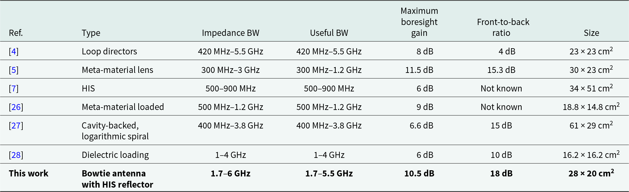
The performance of the antenna is compared with other similar antennas existing in the literature as shown in Table 2. The work presented in paper [Reference Ajith and Bhattacharya4] employs loop directors giving useful bandwidth from 420 MHz to 5.5 GHz with a maximum boresight gain of 8 dBi. However, the FBR obtained in this work is only 4 dB. In paper [Reference Ajith and Bhattacharya5], metamaterial lens is used to give a maximum boresight gain of 11.5 dBi, however with useful bandwith (BW) from 300 MHz to 1.2 GHz only. In paper [Reference Shen7], an HIS-based antenna is designed with a maximum boresight gain of 6 dBi and useful BW from 500 to 900 MHz only. In paper [Reference Liu, Zhang, Liu and Hua26], a meta-material-loaded bowtie antenna with useful bandwidth from 500 MHz to 1.2 GHz with a gain of 8 dBi is presented. In paper [Reference Thaysen27], the design of a cavity-backed logarithmic spiral antenna with useful BW from 400 MHz to 3.8 GHz and maximum boresight gain of 6.6 dBi are presented. Also, the antenna occupies a large size of 61 × 29 cm2. In paper [Reference Liu, Mengqian, Huimin, Yang and Shi28], a dielectric-loaded bowtie antenna with useful BW from 1 to 4 GHz and a maximum boresight gain of 6 dBi are presented. The proposed antenna gives good boresight gain (10.5 dB) and FBR (18 dB) compared to the existing antennas in the literature.
Table 2. Comparison with other existing antennas in the literature
Conclusion
CMA is conducted for the identification of desired and higher order modes for a triangular-elliptical bowtie antenna, and an HIS structure is used to enhance the desired mode and to suppress the higher order unwanted mode. The final designed HIS-based bowtie antenna gives stable and unidirectional radiation characteristics. The developed antenna gives a maximum boresight gain of 10.5 dB and FBR of 18 dB in the useful bandwidth range of 1.7–5.5 GHz. The proposed antenna is a suitable choice for applications like GPR, where higher boresight gain and FBR values are desired.
Author contributions
J.B.K. performed simulations and measurements and contributed in the write up of the manuscript. A.B. conceptualized the work, contributed in reaching the conclusions, and supported in the execution of the work.
Competing interests
The authors report no conflict of interest.

Jagadeesh Babu Kamili was born in Chirala, Andhra Pradesh, India, in 1978. He received B.Tech. degree from SVH College of Engineering, Machilipatnam, in the year 1999, and M.Tech. and Ph.D. degrees from Jawaharlal Nehru Technological University, Hyderabad, India, in 2006 and 2013, respectively. Presently, he is working as a professor and head of the department at St. Ann’s College of Engineering & Technology, Chirala, India. Also, he is a postdoctoral researcher under Certificate of Excellence in Research program from Indian Institute of Technology Kharagpur, India. He received Travel Grant from SERB, Department of Science and Technology (DST), India, to attend International Conference PIERS-2017 in Singapore. Also, he received Best Researcher Award from JNTUK University in the year 2018. He received research grant from AICTE under RPS scheme as principal investigator. He is working on various research projects as International Collaborator with King Abdul Aziz University, Saudi Arabia. He is a senior member of IEEE, fellow of IETE, and life member of IE and ISTE, India. His research areas include printed antennas, meta-materials, ground penetrating radar, and characteristic mode analysis.

Amitabha Bhattacharya was born in Kolkata, India, in 1964. He received the B.Tech. (E&ECE) degree from IIT Kharagpur, in 1986, the M.E. (E&TCE) degree from Jadavpur University, in 1994, and the Ph.D. (E&ECE) degree from IIT Kharagpur, in 1998. In 1986, he started his professional career by joining as a junior research engineer in an ISRO sponsored research project at IIT Kharagpur, where he continued as a senior research assistant in a DRDO sponsored research project, till 1991. In 1997, he joined SAMEER, Mumbai, and the Defence Laboratory, Jodhpur, as a research scientist. In 2000, he joined the teaching profession as an assistant professor with the Department of Electronics and Instrument, Indian School of Mines, Dhanbad, and with the faculty of Electronics and Electrical Communication Engineering Department, IIT Kharagpur, in 2007, where he is currently working as a professor and involved in the teaching and research activities of the RF and Microwave Group of the E&ECE Department. He has published over 100 research publications in international journals and conferences and has written a textbook on Digital Communication. He has been the principal investigator of 27 sponsored research projects and consultancies, and he has conducted 18 sponsored short-term courses around the country, mainly in the areas of electromagnetic environments. He has supervised several Ph.D. thesis and 38 postgraduate thesis. His research interests include microwave imaging, high power microwaves, and microwave stealth technology.


