Hostname: page-component-586b7cd67f-l7hp2 Total loading time: 0 Render date: 2024-11-22T10:55:43.305Z Has data issue: false hasContentIssue false

Flow reversal and multiple states in turbulent Rayleigh–Bénard convection with partially isothermal plates

Published online by Cambridge University Press:  13 May 2024
Jin Hu
Affiliation:
State Key Laboratory of Fluid Power and Mechatronic Systems and Department of Engineering Mechanics, Zhejiang University, Hangzhou 310027, PR China
Shengqi Zhang
Affiliation:
Eastern Institute for Advanced Study, Eastern Institute of Technology, Ningbo 315201, PR China
Zhenhua Xia*
Affiliation:
State Key Laboratory of Fluid Power and Mechatronic Systems and Department of Engineering Mechanics, Zhejiang University, Hangzhou 310027, PR China
*
Email address for correspondence: [email protected]

Abstract

This paper examines turbulent Rayleigh–Bénard convection in a two-dimensional square cavity with partially isothermal conducting plates on the horizontal walls. The study reveals that controlling the relative locations of the partially isothermal plates can accelerate or completely suppress the reversals of large-scale circulation. The heat transfer efficiency, which is characterised by the time-averaged Nusselt number, is generally higher than that of the traditional Rayleigh–Bénard convection, and can be further enhanced when the reversal is fully suppressed. The reversal in our cases is mainly caused by the competition between the two alternately growing ‘corner’ vortices, fed by the detaching plumes from the hot/cold plates. This differs from those reported in traditional Rayleigh–Bénard convection. Fourier mode decomposition of the kinetic energy, reflecting the diverse contributors, in the reversing cases further emphasises the distinction between the current system and traditional Rayleigh–Bénard convection. In addition, multiple states were observed where the conducting plates were positioned at specific relative locations and had different initial conditions. It has been observed that the difference in Nusselt numbers between the anticlockwise and clockwise states increases linearly with the distance between the upper cold and lower hot plates. Moreover, the analysis of the buoyancy moment and the stability of the primary roll structure suggests that the higher heat transfer efficiency between the two states is strongly linked to a more stable primary roll structure. This study presents a new approach for controlling flow reversal and improving heat transfer efficiency by modifying the non-global conducting boundary and initial conditions.

Type
JFM Papers
Copyright
© The Author(s), 2024. Published by Cambridge University Press

1. Introduction

Rayleigh–Bénard convection (RBC) is one of the crucial ideal models that has been used extensively to investigate important issues related to heat transport and flow dynamics in a wide range of research fields, including astrophysics, geophysics and engineering (Wyngaard Reference Wyngaard1992; Ahlers, Grossmann & Lohse Reference Ahlers, Grossmann and Lohse2009; Lohse & Xia Reference Lohse and Xia2010). Among the various investigations, the one concerning the reversal of large-scale circulation (LSC) and its interplay with heat transfer efficiency retains enduring significance (Grossmann & Lohse Reference Grossmann and Lohse2000, Reference Grossmann and Lohse2001; Benzi Reference Benzi2005; Wang, Zhou & Sun Reference Wang, Zhou and Sun2020a; Wu, Wang & Zhou Reference Wu, Wang and Zhou2022). One popular viewpoint is that the LSC is accomplished by the growth, squeezing and reconnection of the rolls in two-dimensional (2-D) and quasi-2-D RBC systems (Sugiyama et al. Reference Sugiyama, Ni, Stevens, Chan, Zhou, Xi, Sun, Grossmann, Xia and Lohse2010; Chandra & Verma Reference Chandra and Verma2011, Reference Chandra and Verma2013), with corner rolls playing a pivotal role in the reversal process. Chandra & Verma (Reference Chandra and Verma2013) reported large fluctuations in heat transport due to the flow reconfiguration during the reversal. Recently, experiments also indicate that the instability of the LSC may also be crucial to the flow reversals (Chen et al. Reference Chen, Huang, Xia and Xi2019), especially for the set-ups without corner flows (Wang et al. Reference Wang, Lai, Song and Tong2018c; Chen, Wang & Xi Reference Chen, Wang and Xi2020). In addition, researchers started to focus on controlling the reversal behaviour using different methods (Huang et al. Reference Huang, Wang, Xi and Xia2015; Zhang et al. Reference Zhang, Xia, Zhou and Chen2020, Reference Zhang, Chen, Xia, Xi, Zhou and Chen2021). One of the recent works was carried out by Huang & Zhang (Reference Huang and Zhang2023), who successfully eliminated the reversal and enhanced the vertical heat transfer efficiency by injecting heat through one lateral side of the fluid domain and extracting an equal amount of heat from the opposite side.

Over the past few years, the scholarly community has increasingly acknowledged the potential coexistence of diverse flow states in fully developed turbulence. Several findings have indicated that turbulent flows exhibit the capacity to manifest distinct statistically stationary turbulent states, characterised by variations in the length scale of flow structures and corresponding transport properties, despite identical control parameter values (Van Der Poel, Stevens & Lohse Reference Van Der Poel, Stevens and Lohse2011; Huang et al. Reference Huang, Xia, Wan, Shi and Chen2019; Huang, Xia & Chen Reference Huang, Xia and Chen2020; Wang et al. Reference Wang, Wan, Yan and Sun2018a, Reference Wang, Chong, Stevens, Verzicco and Lohse2020b). Examples include multiple states in high-Reynolds-number Taylor–Couette flow (Huisman et al. Reference Huisman, van der Veen, Sun and Lohse2014; Ostilla-Mónico, Lohse & Verzicco Reference Ostilla-Mónico, Lohse and Verzicco2016), in von Kármán swirling flow (Ravelet et al. Reference Ravelet, Marié, Chiffaudel and Daviaud2004; Faranda et al. Reference Faranda, Sato, Saint-Michel, Wiertel, Padilla, Dubrulle and Daviaud2017), in Couette flow (Zimmerman, Triana & Lathrop Reference Zimmerman, Triana and Lathrop2011; Xia et al. Reference Xia, Shi, Cai, Wan and Chen2018) and in RBC (Xi & Xia Reference Xi and Xia2008; Van Der Poel et al. Reference Van Der Poel, Stevens and Lohse2011; Xie, Ding & Xia Reference Xie, Ding and Xia2018; Wang et al. Reference Wang, Chong, Stevens, Verzicco and Lohse2020b,Reference Wang, Verzicco, Lohse and Shishkinac). Xi & Xia (Reference Xi and Xia2008) experimentally investigated rotating RBC cells with aspect ratios of $1$, $1/2$ and $1/3$, revealing the coexistence of a single circulating roll and those with two vertically stacked counter-rotating rolls, with the former demonstrating higher heat transfer efficiency. Wang et al. (Reference Wang, Wan, Yan and Sun2018a, Reference Wang, Verzicco, Lohse and Shishkina2020c) conducted numerical investigations into 2-D convection featuring varying tilt angles and aspect ratios, uncovering the coexistence of multiple states under conditions characterised by small angles and large aspect ratios, as well as appropriate initial flow conditions. It is worthy noting that previous studies on the multiple states of traditional RBC have mostly concentrated on the different numbers of rolls.

In traditional RBC, it is typically assumed that the bottom hot and top cold plates have a uniform temperature or heat flux. However, the situations in nature and engineering applications often deviate from this requirement for uniformity. For example, in comparison with the oceanic lithosphere, the average heat loss through the continents is much lower (Lenardic et al. Reference Lenardic, Moresi, Jellinek and Manga2005). Taking polar ocean convection as an example, the surface heat flux of ice-covered areas is typically two orders of magnitude lower than that of open ocean regions. Consequently, the ice surface can be approximated as an adiabatic layer compared to the sea surface. In addition, the influence of continental plates on mantle convection can be categorised as a similar situation. This can be simplified into the model with an insulating plate drifting over a thermally convective fluid, as utilised in laboratory experiments (Zhang & Libchaber Reference Zhang and Libchaber2000; Zhong & Zhang Reference Zhong and Zhang2007; Whitehead, Shea & Behn Reference Whitehead, Shea and Behn2011; Wang, Huang & Xia Reference Wang, Huang and Xia2017). These experimental results confirm that the insulating plate indeed poses a non-negligible effect on the dynamic coupling between the plate and underlying fluid, and that this effect varies with plate size. Numerical studies by Mao (Reference Mao2021, Reference Mao2022) have delved into details of the variations of plate motion with plate size and the underlying mechanism. In addition to the aforementioned set-up, investigations on turbulent convection based on non-uniform thermal boundary conditions have also been considered in recent years (Bakhuis et al. Reference Bakhuis, Ostilla-Mónico, Van Der Poel, Verzicco and Lohse2018; Nandukumar et al. Reference Nandukumar, Chakraborty, Verma and Lakkaraju2019; Ostilla-Mónico & Amritkar Reference Ostilla-Mónico and Amritkar2020; Bassani et al. Reference Bassani, Poggi, Ridolfi and Von Hardenberg2022; Zhao et al. Reference Zhao, Zhang, Wang, Wu, Chong and Zhou2022). For example, Zhao et al. (Reference Zhao, Zhang, Wang, Wu, Chong and Zhou2022) numerically investigated the 2-D RBC by applying sinusoidally distributed heating to the bottom plate and Ostilla-Mónico & Amritkar (Reference Ostilla-Mónico and Amritkar2020) simulated the 3-D RBC with a top cold plate having a mixture of adiabatic and isothermal boundary conditions.

In this paper, we propose a new configuration where partially isothermal horizontal plates, i.e. a lower hot plate and an upper cold plate, each spanning half the length of the square cavity, are positioned at a number of different relative locations. Here, we choose direct numerical simulations of the 2-D configuration due to the much cheaper computational cost and convenient comparison with existing results in the literature. We show that the proposed configuration can accelerate or suppress the reversals as well as the corresponding heat transfer efficiency, depending on the relative location of the double isothermal plates. The reversal mechanism associated with the present set-up and the coexistence of multiple states due to different initial fields in non-reversing systems are also discussed. The corresponding relations between the variances in heat transfer efficiencies and the relative locations of the double conducting plates are quantitatively analysed.

2. Basic set-up

2.1. Governing equations and simulation parameters

In this paper, we consider buoyancy-driven 2-D flows in a square cavity using the Boussinesq approximation. The centre of the cavity is defined as the origin of the coordinates. We use the cavity height $\hat {H}$, free-fall velocity $\hat {U}=(\hat {g}\hat {\beta }\hat {\Delta }\hat {H})^{1/2}$, free-fall time $\hat {T}=\hat {H}/\hat {U}$ and the temperature difference between lower and upper conducting plates $\hat {\varDelta }=\hat {\theta _l}-\hat {\theta _u}$ as length, velocity, time and temperature scales, respectively. Here, $\hat {g}$ is the gravitational acceleration and $\hat {\beta }$ is the thermal expansion coefficient. With $\theta =[\hat {\theta }-(\hat {\theta _l}+\hat {\theta _u})/2]/\hat {\varDelta }$, the governing equations and related boundary conditions on the vertical walls can be non-dimensionalised as follows:

(2.1)\begin{equation} \left. \begin{gathered} \displaystyle\boldsymbol{\nabla}\boldsymbol{\cdot}{\boldsymbol{u}}=0,\\ \displaystyle\frac{\partial{\boldsymbol{u}}}{\partial t} +{\boldsymbol{u}}\boldsymbol{\cdot} \boldsymbol{\nabla}{\boldsymbol{u}}={-}\boldsymbol{\nabla} p+\sqrt{\frac{Pr}{{Ra}}} \nabla^2{\boldsymbol{u}}+\theta{\boldsymbol{j}},\\ \displaystyle\frac{\partial \theta}{\partial t}+{\boldsymbol{u}}\boldsymbol{\cdot}\boldsymbol{\nabla} \theta=\frac{1}{\sqrt{Ra Pr}}\nabla^2\theta,\\ \displaystyle{\boldsymbol{u}}=0,\quad \partial\theta /\partial x=0,\quad \mbox{on}\ x={\pm} 0.5. \end{gathered}\right\}\end{equation}

Here, $Ra=\hat {g}\hat {\beta }\hat {\Delta }\hat {H}^3/(\hat {\nu }\hat {\alpha })$ is the Rayleigh number and $Pr=\hat {\nu }/\hat {\alpha }$ is the Prandtl number, with $\hat {\nu }$ and $\hat {\alpha }$ being the kinematic viscosity and the thermal diffusivity, respectively. We introduce $x_l$ and $x_u$ to denote the centre locations of the isothermal plates on the lower and upper walls, respectively. The boundary conditions on the horizontal walls are given by

(2.2a,b)$$\begin{gather} {y={+}0.5:{\boldsymbol{u}}=0,\quad \left\{\!\!\begin{array}{ll} \displaystyle \theta={-}0.5, & |x-x_u|\leqslant 0.25,\\ \displaystyle \partial \theta / \partial y=0, & |x-x_u|> 0.25, \end{array} \right.} \end{gather}$$
(2.3a,b)$$\begin{gather}{y={-}0.5:{\boldsymbol{u}}=0,\quad \left\{\!\!\begin{array}{ll} \displaystyle \theta={+}0.5, & |x-x_l|\leqslant 0.25,\\ \displaystyle \partial \theta / \partial y=0, & |x-x_l|> 0.25. \end{array}\right.} \end{gather}$$

In other words, the four walls are adiabatic except for two isothermal plates with a length of $0.5H$. A sketch of the flow set-up and the corresponding boundary conditions is depicted in figure 1.

Figure 1. Sketch of RBC with partially isothermal plates, where the bottom and top plates are half the length of the cavity size $H$ with centre locating at $x_l$ and $x_u$, respectively.

The above equations are solved using the second-order finite-difference code AFiD (Van Der Poel et al. Reference Van Der Poel, Ostilla-Mónico, Donners and Verzicco2015) with some modifications. The correctness of the present code has been validated by Zhang et al. (Reference Zhang, Chen, Xia, Xi, Zhou and Chen2021). We carried out a total of $9\times 17\times 3$ simulations, where $x_l$ and $x_u$ vary in $[-8,0]/32$ and $[-8,8]/32$, respectively, with an interval $1/32$, and the initial flow field can be stationary, clockwise or anticlockwise. The temperature of the stationary initial flow field is $\theta =(\theta _l+\theta _h)/2$ inside the cavity. The control parameters are $Ra=1\times 10^8$ and $Pr=2$, as what was done by Zhang et al. (Reference Zhang, Xia, Zhou and Chen2020). The number of grid points is $384\times 384$, and the corresponding time step is $2.0\times 10^{-3}$. The grid sizes satisfy the criterion $\varDelta _{x,y}<0.6\ {\min }[\eta _K,\eta _B]$ in the boundary layers (Shishkina et al. Reference Shishkina, Stevens, Grossmann and Lohse2010), where $\eta _K=\hat {\nu }^3/\hat {\varepsilon }({\boldsymbol{x}},t)^{1/4}/\hat {H}$ (with $\hat {\varepsilon }({\boldsymbol{x}},t)$ being the local turbulent dissipation) and $\eta _B=\eta _K Pr^{-1/2}$ are the local Kolmogorov and Batchelor scales, respectively. The time step is small enough so that the Courant–Friedrichs–Lewy number is smaller than 0.2. In the following, $\langle \cdot \rangle _t$, $\langle \cdot \rangle _x$ and $\langle \cdot \rangle _y$ denote the average in time, along the $x$-axis and along the $y$-axis, respectively. For simplicity, the pair $(x_l,x_u)$ always denotes the system with central locations of hot and cold plates at $x_l$ and $x_u$, respectively.

2.2. Reversal detection

In this study, the angular momentum $L(t)=\langle x{\cdot } v-y{\cdot } u\rangle _{x,y}$ is used as the reversal indicator, where the value $L<0$ usually corresponds to a clockwise LSC and vice versa (Sugiyama et al. Reference Sugiyama, Ni, Stevens, Chan, Zhou, Xi, Sun, Grossmann, Xia and Lohse2010; Wang et al. Reference Wang, Xia, Wang, Sun, Zhou and Wan2018b). To detect the reversal quantitatively, the criterion based on the two peaks of the probability density function of $L(t)$ (Huang & Xia Reference Huang and Xia2016; Zhang et al. Reference Zhang, Chen, Xia, Xi, Zhou and Chen2021) was adopted. Following Zhang et al. (Reference Zhang, Chen, Xia, Xi, Zhou and Chen2021), we use $\tau _-$ to denote the time interval between an ‘anticlockwise to clockwise’ reversal and a successive ‘clockwise to anticlockwise’ reversal, whereas $\tau _+$ corresponds to the opposite situation. In other words, $\tau _-$ and $\tau _+$ are the time spans of the system when it is in the clockwise and anticlockwise states between two successive reversals, respectively. $N_-$ and $N_+$ denote the numbers of detected $\tau _-$ and $\tau _+$, respectively. Correspondingly, $\langle \tau _-\rangle$ and $\langle \tau _+\rangle$ denote the average of detected $\tau _-$ and $\tau _+$, respectively, and they can be written as

(2.4a,b)\begin{equation} \langle\tau_-\rangle= \frac{1}{N_-}\sum_{i=1}^{N_-} \tau_{-,i}, \quad \langle\tau_+\rangle= \frac{1}{N_+}\sum_{i=1}^{N_+} \tau_{+,i}. \end{equation}

It should be noted that, when the system does not prefer any LSC orientation, such as traditional RBC, $N_-\approx N_+$ and $\langle \tau _-\rangle \approx \langle \tau _+\rangle$.

Here, we use $\langle \tau _-\rangle _{max}$ and $\langle \tau _+\rangle _{max}$ to represent the maximum values of $\langle \tau _-\rangle$ and $\langle \tau _+ \rangle$ across all reversing systems, respectively. For accuracy of flow statistics, all simulations are run for more than $100\max [\langle \tau _-\rangle _{max},\langle \tau _+\rangle _{max}]$ and the statistics are computed within a time range over $40\max [\langle \tau _-\rangle _{max},\langle \tau _+\rangle _{max}]$. Therefore, in the present context, ‘non-reversing’ only means that no reversal is observed in a period of $100\max [\langle \tau _-\rangle _{max},\langle \tau _+\rangle _{max}]$, which is around 65 000 free-fall times.

3. Results and discussion

3.1. Reversal and heat transfer efficiency

To systematically investigate flow structures and turbulent statistics, we consider the simplest cases with stationary initial fields, i.e. $\boldsymbol {u}=0$ and $\theta =(\theta _l+\theta _h)/2$. The flow will eventually reach a stationary state with the given set-up, where the LSC will rotate either anticlockwise or clockwise, or constantly reverse, depending on the relative locations of $x_l$ and $x_u$. Figure 2 shows the phase diagram of the final LSC for fixed physical parameters $Ra=1\times 10^8$ and $Pr=2$ and varying $x_l$ and $x_u$, together with the values of the effective Nusselt number, defined as $Nu_{eff}=(\langle Nu\rangle _t-\langle Nu_0\rangle _t)/\langle Nu_0\rangle _t$. Here, $Nu_{eff}$ quantifies the relative variation of the time-averaged Nusselt number $\langle Nu\rangle _t$ compared with $\langle Nu_0\rangle _t$ (Zhang et al. Reference Zhang, Xia, Zhou and Chen2020) of the traditional RBC cell at the same $Ra$ and $Pr$. The instantaneous Nusselt number of the case with $(x_l, x_u)$ is defined as

(3.1)\begin{equation} Nu(t)={-}\frac{1}{2}\bigg[ \left. \left\langle\left.\frac{\partial\theta}{\partial y}\right|{|x-x_l|\leqslant 0.25}\right\rangle\right|_{y={-}0.5}+ \left. \left\langle\left.\frac{\partial\theta}{\partial y}\right|{|x-x_u|\leqslant 0.25}\right\rangle\right|_{y=0.5} \bigg]. \end{equation}

It is obvious that the data in figure 2 are symmetrical about the lines $x_l=\pm x_u$, which is consistent with the mathematical symmetries of the corresponding systems. For sufficiently long periods, reversals of the LSC can only be observed when $(x_l,x_u)$ is in the range of $\{x_l\leqslant -4/32\} \cap \{x_u\leqslant -4/32\}$. For the present cases with $\{x_l>-4/32\}$ or $\{x_u>-4/32\}$, i.e. the left end of either isothermal plate is more than $\hat {H}/8$ away from the left sidewall, the reversal of LSC is suppressed. For all possible relative locations $(x_l,x_u)$ of isothermal plates, $\langle Nu\rangle _t$ in most cases is larger than that of the traditional RBC cell, $\langle Nu_0\rangle _t$, except for the three cases with $(-8/32,-8/32)$, $(-8/32,-7/32)$ and $(-7/32,-8/32)$. When the reversal is suppressed, the heat transfer efficiency can be further increased as compared to the reversing cases, and the maximum occurs when $x_l=x_u$, with the highest $Nu_{eff}$ reaching $13.8\,\%$.

Figure 2. Phase diagram in $x_u{-}x_l$ plane with values of the effective Nusselt number, defined as $Nu_{eff}=(\langle Nu\rangle _t-\langle Nu_0\rangle _t)/\langle Nu_0\rangle _t$, at $Ra=1\times 10^8$ and $Pr=2$. Crosses and squares correspond to stable anticlockwise and clockwise LSCs, respectively, and circles to detected reversals, where $Nu_0$ denotes the Nusselt number of the traditional RBC cell at the same $Ra$ and $Pr$. Here, the initial velocity and temperature fields are ${\boldsymbol{u}}=0$ and $\theta =(\theta _l+\theta _u)/2$, respectively.

Figure 3 presents time series of angular momentum $L(t)$ alongside the corresponding Nusselt number $Nu(t)$ in a period of 5000 free-fall times for two reversing cases, $(x_l,x_u)=(-8/32,-8/32)$,$(-7/32,-5/32)$, and two non-reversing cases characterised by distinct final stable orientations $(x_l,x_u)=(-1/32,-6/32)$, $(-4/32,2/32)$. In addition, the results of the traditional RBC are illustrated by the black solid line for comparison. For clarity, here $Nu(t)$ obtained from the traditional RBC has been offset by $-6$. Based on the outcomes shown in figures 3(a) and 3(c), in conjunction with comprehensive statistical analyses of the remaining reversing cases, it is evident that reversal frequencies in our systems are higher than that exhibited in the traditional RBC. Furthermore, it is discernible that not every instance of reversal within our system culminates in success. Intriguingly, this phenomenon manifests at a significantly higher probability compared with its occurrence within traditional RBC, which may be attributed to potential disparities in the reversal mechanisms. The findings depicted in figures 3(b) and 3(d) corroborate that the suppression of reversal positively impacts heat transfer efficiency, which is consistent with the results shown in figure 2. Within non-reversing systems, the stability of flow structures is stronger, as evidenced by a reduction in the amplitude of fluctuations of $Nu(t)$.

Figure 3. Time series of angular momentum $L(t)$ are shown in panels (a,c), accompanied by corresponding Nusselt number $Nu(t)$ in panels (b,d). In panels (a,b), $(x_l,x_u)=(-8/32,-8/32)$ and $(-1/32,-6/32)$, and the corresponding $\langle Nu\rangle _t$ are $24.56$ and $27.14$. In panels (c,d), $(x_l,x_u)=(-7/32,-5/32)$ and $(-4/32,2/32)$, and the corresponding $\langle Nu\rangle _t$ are $25.73$ and $26.88$. The black solid lines denote the outcomes obtained from the traditional RBC at the same $Ra$ and $Pr$, and the corresponding $\langle Nu\rangle _t$ is $25.02$. For clarity, $Nu(t)$ obtained from the traditional RBC has been offset by $-6$.

Building upon the time intervals defined in § 2.2 for reversals, a rigorous quantitative analysis of the 25 reversing cases has been undertaken. Figure 4(a) illustrates the variations with $x_u$ of $\langle \tau _-\rangle /\langle \tau _0\rangle$ and $\langle \tau _+\rangle /\langle \tau _0\rangle$ at $x_l=-8/32$ and $x_l=-4/32$. Here, $\langle \tau _-\rangle$ and $\langle \tau _+\rangle$ represent the mean durations of the system in its clockwise and anticlockwise states, respectively, spanning the interval between two consecutive reversals. Here $\langle \tau _0\rangle$ is the mean time interval between successive reversals in traditional RBC. It is easily seen that $\langle \tau _{-,+}\rangle < 0.4\langle \tau _0\rangle$ and that $\langle \tau _-\rangle \neq \langle \tau _+\rangle$ in general, documenting that the LSCs with different $(x_l,x_u)$ prefer a certain orientation. Figure 4(b) shows the variations of $(\langle \tau _-\rangle -\langle \tau _+\rangle )/\langle \tau _0\rangle$ at different $x_l-x_u$ for the 25 cases. It can be seen that although the data are rather scattered, they show a general tendency, i.e. as the location of the hot plate relative to the cold plate changes from left to right, the preferred orientation of the corresponding LSC in reversing systems gradually tends to be from clockwise to anticlockwise, which is consistent with physical intuitions. For fixed $x_l-x_u$, $\langle \tau _-\rangle -\langle \tau _+\rangle$ varies with $x_l$, and the variations are larger when $|x_l-x_u|$ is smaller. These results imply that the preferred orientation of the LSC is influenced by the actual locations of the hot and cold plates, especially when they are close to each other in the $x$-direction.

Figure 4. (a) Variations of $\langle \tau _-\rangle /\langle \tau _0\rangle$ and $\langle \tau _+\rangle /\langle \tau _0\rangle$ with $x_u$ at $x_l=-8/32$ and $x_l=-4/32$. (b) Scatter plot of $(\langle \tau _-\rangle -\langle \tau _+\rangle )/\langle \tau _0\rangle$ for reversing systems with the relative location of isothermal plates $x_l-x_u$. Here, $\langle \tau _0\rangle$ is the mean time interval between successive reversals in traditional RBC.

We now turn our attention to the reversal phenomena, and the case with $(x_l,x_u)=(-8/32,-8/32)$ is used as an example, where the difference between $\langle \tau _-\rangle$ and $\langle \tau _+\rangle$ is small, as shown in figure 4. Figures 5(a)–5(c) and figures 5(d)–5(f) depict the three typical frames of the velocity and temperature fields during a successive ‘clockwise to anticlockwise’ reversal of the case with $(x_l,x_u)=(-8/32,-8/32)$ and traditional RBC, respectively. Supplementary movie 1 available at https://doi.org/10.1017/jfm.2024.388 displays more frames of the case with $(x_l,x_u)=(-8/32,-8/32)$ during several reversals. Figures 5(a)–5(c) show that in our system, a successful reversal can be triggered by the growth of corner vortices near the left sidewall, which is closer to the isothermal plates. One of the corner vortices (e.g. the upper-left corner vortex in figure 5a) is energetically fed by detaching plumes from the upper thermal boundary layers, which is similar to the process described in Sugiyama et al. (Reference Sugiyama, Ni, Stevens, Chan, Zhou, Xi, Sun, Grossmann, Xia and Lohse2010). This corner vortex grows larger and stronger, squeezes the main roll (see figure 5b), and eventually replaces it as the new main roll (see figure 5c). Simultaneously, the previous main roll is squeezed smaller, and evolves to a new corner vortex (for instance, the lower-left vortex in figure 5c). The corner vortices close to the right sidewall are barely visible, and they cannot be fed by detaching plumes from the thermal boundaries. In the present set-up, there is no reconnection of two attracting corner rolls in the diagonal with the same sign of vorticity occurs during the reversal. This is in contrast to the reversal processes in traditional RBC, where the vortex reconnection of two attracting corner rolls causes them (Chandra & Verma Reference Chandra and Verma2013), as shown in figures 5(d)–5(f). The reversal patterns shown in figures 5(a)–5(c) are generally observable across the remaining 24 cases, as confirmed by the supplementary movies 2–4. These movies show the reversal in the cases with $(x_l,x_u)=(-8/32,-4/32)$, $(-4/32,-8/32)$ and $(-4/32,-4/32)$, respectively. Therefore, we conclude that the reversal process in the present set-up differs from that in traditional RBC. Although the corner vortices are crucial in both cases, vortex reconnection and restructuring of the main roll are not necessary in the present set-up. If $\{x_l>-4/32\}$ or $\{x_u>-4/32\}$, the continuous feeding of the corner rolls from the detaching plumes from the isothermal plates is weak and, therefore, no reversal occurs, as depicted in figure 2.

Figure 5. Typical snapshots of instantaneous temperature (colour) and velocity (vectors) fields during a ‘clockwise to anticlockwise’ reversal for $(x_l,x_u)=(-8/32,-8/32)$ in panels (ac) and for the traditional RBC in panels (df). Panels (ac) and panels (df) both represent the direction of advancing in time.

3.2. Modal analysis

Another scenario from figures 5(a)–5(c) and the supplementary movies is that the occurrence of four rolls as illustrated in figure 5(e) is rather rare. To verify this, we examined the flow energy using Fourier mode decomposition (Wagner & Shishkina Reference Wagner and Shishkina2013; Chong et al. Reference Chong, Wagner, Kaczorowski, Shishkina and Xia2018; Chen et al. Reference Chen, Huang, Xia and Xi2019). Briefly, each instantaneous velocity field $(u,v)$ is projected onto the Fourier modes as

(3.2)\begin{equation} \left. \begin{gathered} \displaystyle u^{m,n}=2\sin{\left( m{\rm \pi} \tilde{x}\right )}\cos{\left(n{\rm \pi} \tilde{y}\right)},\\ \displaystyle v^{m,n}={-}2\cos{\left( m{\rm \pi} \tilde{x}\right )}\sin{\left(n{\rm \pi} \tilde{y}\right)},\end{gathered}\right\} \end{equation}

where $\tilde{x}\triangleq x+0.5$ and $\tilde {y}\triangleq y+0.5$. The projection is done component-wise by a scalar product in the $\rm {L_2}$-space of our 2-D subdomain. Then the expansion coefficients have certain expressions $A^{m,n}_u(t)=\langle u(t)u^{m,n}\rangle _{x,y}$ and $A^{m,n}_v(t)=\langle v(t)v^{m,n}\rangle _{x,y}$. Therefore, we obtain the kinetic energy $E_{m,n}(t)$ contributed by the $(m,n)$ mode (Zhang et al. Reference Zhang, Chen, Xia, Xi, Zhou and Chen2021):

(3.3)\begin{equation} E_{m,n}(t)=\tfrac{1}{2}([A_u^{m,n}(t)]^2+[A_v^{m,n}(t)]^2). \end{equation}

Here, for simplicity, we consider only the first four modes with $m,n\in \{1,2\}$. Figure 6 shows time series of the kinetic energy contributed by those four modes ($(1,1)$, $(1,2)$, $(2,1)$, $(2,2)$) and the absolute value of angular momentum $|L(t)|$ when $(x_l,x_u)=(-8/32,-8/32)$ and $(-4/32,-5/32)$, respectively. It can be seen that $E_{1,2}$ and $E_{1,1}$ always alternate as the dominant mode, up to a maximum share of between $70\,\%$ and $85\,\%$. The contributions from the other two modes are always very small. The time evolution trends of $|L(t)|$ and $E_{1,1}$ are essentially the same (the correlation coefficient is around 0.99), suggesting that the choice of using angular momentum to indicate reversals is reasonable. Certainly, in the remaining 23 reversing cases, the aforementioned characteristics illustrated in figure 6 persist.

Figure 6. Time series of kinetic energy contributed by $(1,1)$, $(1,2)$, $(2,1)$ and $(2,2)$ (corresponding to black, red, purple and green solid lines), as well as the absolute value of angular momentum (solid blue line with symbols) when $(x_l,x_u)$ is (a) $(-8/32,-8/32)$ and (b) $(-4/32,-5/32)$.

We further calculate the time-averaged kinetic energy contributions from four modes for all $x_l$ and $x_u$. Here we take the results of $x_l=x_u$, $x_u=-4/32$, $x_u=-8/32$ and $x_u=8/32$ in figure 7 as examples. Clearly, the contributions of the different modes to the kinetic energy differ significantly between reversing and non-reversing systems. In reversing systems, i.e. $\{x_l\leqslant -4/32\} \cap \{x_u\leqslant -4/32\}$, the dominant modes are always $(1,1)$ and $(1,2)$, which is consistent with figures 5 and 6. Figures 7(a)–7(c) demonstrate that the two dominant modes contribute comparably to the total kinetic energy, ranging from $30\,\%$ to $45\,\%$. However, their contributions do not vary monotonically with the locations in reversing systems. A larger $\langle E_{1,1}\rangle _t$ typically corresponds to a smaller $\langle E_{1,2}\rangle _t$, and vice versa. The results of modal analysis for reversing systems differ from those of traditional RBC (Sugiyama et al. Reference Sugiyama, Ni, Stevens, Chan, Zhou, Xi, Sun, Grossmann, Xia and Lohse2010; Chandra & Verma Reference Chandra and Verma2011, Reference Chandra and Verma2013). In traditional RBC at the same control parameters, the main contributions are from the modes $(1,1)$ and $(2,2)$, which contribute about 51.5 % and 17.5 %, respectively. These results once again confirm that the reversal process in the present system with partially isothermal horizontal plates differs from that in traditional RBC. The statistics of $\langle E_{m,n}\rangle _t$ in all $(x_l,x_u)$ show that as the system shifts from reversing to non-reversing with increasing $x_l$ or $x_u$, $\langle E_{1,1}\rangle _t/\langle E_{total}\rangle _t$ rises from $30\,\%\sim 45\,\%$ to $88\,\%\sim 90\,\%$, whereas the contributions of the other three modes fall rapidly to almost zero.

Figure 7. Time-averaged kinetic energy contributed from $(1,1)$, $(1,2)$, $(2,1)$ and $(2,2)$ modes under different relative locations of conducting plates: (a) $x_l=x_u\in [-8/32,0/32]$, (b) $x_u=-4/32$, (c) $x_u=-8/32$ and(d) $x_u=8/32$. Panels (bd) correspond to $x_l\in [-8/32,0/32]$. The horizontal dotted and dash-dotted lines show the relative contributions of modes $(1,1)$ and $(2,2)$, respectively, from the traditional RBC.

Figure 2 shows that $Nu_{eff}$ is positive for most cases. However, the variations of $Nu_{eff}$ with $x_l$ under fixed $x_u$ are typically non-monotonic. There are sharp increases when $x_l$ changes from $-4/32$ to $-3/32$ with $-8/32\leqslant x_u\leqslant -4/32$. This change can be attributed to the change of the system's state, from reversing to non-reversing. Previous studies have shown that heat transfer efficiency depends on the flow modes. The single-roll flow structure, corresponding to the $(1,1)$ Fourier mode, generally exhibits greater heat transfer efficiency (Van Der Poel et al. Reference Van Der Poel, Stevens and Lohse2011; Xi et al. Reference Xi, Zhang, Hao and Xia2016; Xu et al. Reference Xu, Chen, Wang and Xi2020). Our results show that $Nu(t)$ and $E_{1,1}(t)$ have a positive correlation with a time lag of around 10–30 free-fall times, whereas $Nu(t)$ and $E_{1,1}(t)$ have a negative correlation in reversing systems, which are consistent with the findings of Xu et al. (Reference Xu, Chen, Wang and Xi2020). As the system changes its state from reversing to non-reversing, only the heat transfer-enhancing $(1,1)$ mode is present, resulting in a significant increase in $Nu_{eff}$. In cases where $Nu_{eff}$ varies with $x_l$ in reversing scenarios, the behaviours of $Nu(t)$ and, thus, $Nu_{eff}$ are complicated by the competitions and interactions of the $(1,1)$ mode and the $(1,2)$ mode, as well as other modes. In the non-reversing cases, the stability of the $(1,1)$ mode, which is defined as $S^{1,1}=\langle E_{1,1}\rangle /D(E_{1,1})$ with $D(E_{1,1})$ representing the standard deviation of $E_{1,1}$ (Chen et al. Reference Chen, Huang, Xia and Xi2019; Xu et al. Reference Xu, Chen, Wang and Xi2020), was investigated, and the results showed that despite their roughly similar trends, $S^{1,1}$ and $Nu_{eff}$ exhibit distinct behaviours. Therefore, Consequently, it is also challenging to comprehend the variation of $Nu_{eff}$ with $x_l$ when $x_u$ is fixed based on the stability of the $(1,1)$ mode due to the variation of boundary conditions under different $x_l$. Further work is required to gain a clear and solid understanding of the non-monotonic variations of $Nu_{eff}$ with $x_l$.

3.3. Multiple states

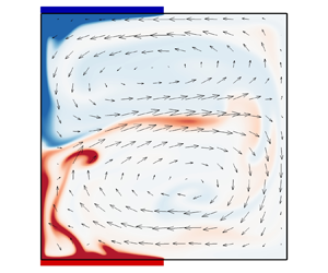
In traditional RBC, multiple states have been identified when the large-scale flows and turbulent statistics exhibit different behaviours despite using identical control parameters and boundary conditions (Xi & Xia Reference Xi and Xia2008; Van Der Poel et al. Reference Van Der Poel, Stevens and Lohse2011; Xie et al. Reference Xie, Ding and Xia2018; Wang et al. Reference Wang, Chong, Stevens, Verzicco and Lohse2020b,Reference Wang, Verzicco, Lohse and Shishkinac). The presence of multiple states is often linked to distinct initial conditions, prompting research into the effect of initial flow fields. The present study adopts a configuration comprising three distinct initial velocity fields, as outlined in § 2.1. The phenomenon of multiple states was observed in our system, as shown in figure 8(a) and 8(b), where typical snapshots of instantaneous temperature and velocity fields for the final steady anticlockwise (AS) LSC and clockwise (CS) LSC, respectively, for $(x_l,x_u)=(-3/32,1/32)$ are presented. Time series of the two states are also presented, respectively, in the supplementary movies 5 and 6. It is important to note that both the AS LSC and CS LSC are highly stable, and their orientations remain unchanged for a very long time during the simulations. The time series of the angular momentum $L(t)$ shown in figure 9(a) supports this claim, where $L(t)>0$ and $L(t)<0$ last for $10^4$ free-fall times for the AS and CS states, respectively. In the present set-up, different orientations of LSC are accompanied by different transport properties, despite the system having the same control parameters and boundary conditions. Figure 9(b) displays the time series of $Nu(t)$, corresponding to the $L(t)$ depicted in figure 9(a). It is evident that the $Nu(t)$ values of the AS state are consistently higher than those for the CS state, leading to a 2.71 absolute increase in $\langle Nu\rangle _t$.

Figure 8. Typical snapshots of instantaneous temperature (colour) and velocity (vectors) fields of (a) anticlockwise state (AS) and (b) clockwise state (CS) at $(x_l,x_u)=(-3/32,1/32)$.

Figure 9. Time series of (a) angular momentum $L(t)$ and (b) corresponding Nusselt number $Nu(t)$ of stable anticlockwise state (AS) and clockwise state (CS) when $(x_l,x_u)=(-3/32,1/32)$.

Before we continue our discussion, we would like to address the term ‘multiple states’ used in this paper. As noted by an anonymous referee, the AS and CS LSCs belong to two branches of the bifurcation diagram in terms of dynamical systems and bifurcation theory. Therefore, they can be classified as multiple states, even in traditional RBC. However, the term ‘multiple states’ in turbulence has a stronger meaning than the above in dynamical systems and bifurcation theory, although it has not been strictly defined. As stated in Wang et al. (Reference Wang, Verzicco, Lohse and Shishkina2020c) and Xia et al. (Reference Xia, Huang, Xie and Zhang2023), ‘multiple states’ in turbulence typically refers to statistically stationary states with different transport properties, where the large-scale flow may exhibit varying sizes/numbers of rolls. In this context, the square RBC system with a single AS or CS LSC cannot be considered to have multiple states, as their $\langle Nu\rangle _t$ values are generally the same due to the system's inherent symmetry. However, in the current set-up, the system's inherent symmetry properties are broken for most cases, resulting in different $\langle Nu\rangle _t$ values for the states with stable AS or CS LSC. Therefore, these states can be considered as multiple states.

The occurrence of multiple states across all $x_l$ and $x_u$ under the current three initial field conditions has been investigated systematically. The results illustrate that the 25 reversing cases persist in reversing, while the remaining non-reversing cases maintain their non-reversing nature. However, in the latter cases, it is worth noting that the ultimately stable orientation of the LSCs in several cases may manifest either CS or AS states, contingent upon the initial velocity field employed. In essence, the current configuration for certain values of $x_l$ and $x_u$ can undergo multiple states. Figure 10(a) shows the cases within $-3/32 \leqslant x_l\leqslant 0$ and $-3/32 \leqslant x_u\leqslant 3/32$, where multiple states occur based on the three different initial velocity fields. Here, we refer to the cases without multiple states as the ‘insensitive’ pattern, or pattern 1, given that the orientation of the steady LSC is independent of the three initial velocity fields used. Conversely, cases featuring multiple states are denoted as the ‘sensitive’ pattern or pattern 2. As per figure 10(a), 13 cases exhibit multiple states, most of which are in close proximity to the configuration where $-3/32 \leqslant x_l=x_u \leqslant 0$. This indicates that as the left–right symmetry of the system is broken, its susceptibility to the initial field becomes more pronounced, particularly as its up–down symmetry strengthens. It is important to note that cases experiencing multiple states are dispersed. Three cases, with $(x_l,x_u)$ being $(-3/32,0/32)$, $(-2/32,1/32)$ and $(-1/32,1/32)$, belong to the insensitive pattern based on the three different initial set-ups presented. It is hypothesised that these three cases may also experience multiple states, but the proper triggering condition has not yet been identified. For the systems with stronger symmetry violation, indicated by larger values of $|x_u-x_l|$, it is believed that they are unlikely to admit multiple states.

Figure 10. (a) Distributions of the ‘insensitive’ (pattern 1) and ‘sensitive’ (pattern 2) patterns with $-3/32 \leqslant x_l\leqslant 0/32$ and $-3/32 \leqslant x_u\leqslant 3/32$; (b) differences in Nusselt numbers between AS ($\langle Nu_+\rangle _t$) and CS ($\langle Nu_-\rangle _t$) states (normalised by $\langle Nu_0\rangle _t$) with varying $x_u-x_l$.

Figure 10(b) demonstrates the differences in Nusselt numbers between AS ($\langle Nu_+\rangle _t$) and CS ($\langle Nu_-\rangle _t$) states for the present 13 cases with varying $x_u-x_l$. For situations involving multiple states, there are typically variations in heat transfer capabilities even when the configuration is totally identical except for initial fields. For the four cases where $x_l=x_u$, the system displays symmetry about the $y=0$ plane. The calculated values of $(\langle Nu_+\rangle _t-\langle Nu_-\rangle _t)/\langle Nu_0\rangle _t$ are close to zero, suggesting that the heat transfer efficiencies for the AS and CS states are almost identical. For the remaining nine cases where $x_l$ does not equal $x_u$, an approximately linear increase in $\langle Nu_+\rangle _t-\langle Nu_-\rangle _t$, with a slope of about 0.9, has been observed. The maximum difference of up to $12\,\%$ of $\langle Nu_0\rangle _t$ occurs when $(x_l,x_u)=(-2/32, 2/32)$. When $x_u-x_l$ is fixed, $\langle Nu_+\rangle _t-\langle Nu_-\rangle _t$ fluctuates with $x_l$, indicating that the discrepancies in heat transfer efficiency are also reliant on the specific locations of the hot and cold plates.

It should be noted that CS is the final orientation resulting from stationary initial fields (as shown in figure 2), which is consistent with physical intuition concerning $x_l$ and $x_u$. However, for the system with $(-3/32,1/32)$, the Nusselt numbers of AS are higher than those of CS for 99.9 % of the statistical time. By investigating the results of all systems with multiple states, it can also be found that the sign of angular momentum $L$, which yields higher Nusselt numbers, is always opposite to that obtained using an initial stationary velocity field, i.e. those presented in figure 2.

At last, we would like to provide an explanation on the difference between $\langle Nu_+\rangle _t$ and $\langle Nu_-\rangle _t$ shown in figure 10(b). Based on the significant role played by buoyancy in thermal convection, Zhang et al. (Reference Zhang, Chen, Xia, Xi, Zhou and Chen2021) pointed out that the divergence-free buoyancy force, $\boldsymbol {F}^b=\theta \boldsymbol {j}-\boldsymbol {\nabla } p_\theta$, is the net contribution of the temperature field to the velocity field. Here, $p_\theta$ satisfies the governing equation

(3.4ac)\begin{equation} \nabla^2 p_\theta=\partial\theta/\partial y,\quad\partial p_\theta/\partial x|_{x={\pm} 0.5}=0,\quad\partial p_\theta/\partial y|_{y={\pm} 0.5}=\theta. \end{equation}

Following this, the pressure $p$ in (2.1) can be decomposed into $p_\theta$ and $p_o$, where $p_o$ generally arises from dynamic pressure and external forces. Therefore, the momentum equation in (2.1) can be written as

(3.5)\begin{equation} \frac{\partial{\boldsymbol{u}}}{\partial t} +{\boldsymbol{u}}\boldsymbol{\cdot}\boldsymbol{\nabla}{\boldsymbol{u}}={-}\boldsymbol{\nabla} p_o+\sqrt{\frac{Pr}{{Ra}}}\nabla^2{\boldsymbol{u}}+\underbrace{(\theta{\boldsymbol{j}}-\boldsymbol{\nabla} p_\theta)}_{\text{$\boldsymbol{F}^b$}}. \end{equation}

The corresponding angular momentum equation can be derived as

(3.6)\begin{equation} \frac{d L}{d t}={-}\left\langle{\boldsymbol{r}}\times({\boldsymbol{u}}\boldsymbol{\cdot} \boldsymbol{\nabla}{\boldsymbol{u}})\right\rangle_{x,y}-\left\langle{\boldsymbol{r}}\times\boldsymbol{\nabla} p_o\right\rangle_{x,y}+\sqrt{\frac{Pr}{Ra}}\left\langle{\boldsymbol{r}}\times\nabla^2 {\boldsymbol{u}}\right\rangle_{x,y}+\underbrace{\langle{\boldsymbol{r}}\times {\boldsymbol{F}}^b\rangle_{x,y}}_{\text{$\boldsymbol{\sigma}$}}. \end{equation}

Therefore, the buoyancy moment $\boldsymbol {\sigma }=\langle \boldsymbol {r}\times \boldsymbol {F}^b\rangle _{x,y}$ can be regarded as the net contribution of the buoyancy to the angular momentum. Figures 11(a) and 11(b) show time series of $\textrm {d}L(t)/\textrm {d}t$ and $\sigma (t)$ when $(x_l,x_u)=(-3/32,1/32)$ with AS and CS states, respectively. We observe a strong correlation between $\textrm {d}L(t)/\textrm {d}t$ and those of $\sigma (t)$, as their peaks and valleys occur roughly simultaneously. This suggests that the buoyancy moment dynamically corresponds to changes in the time derivative of angular momentum, underscoring its significant role in the angular momentum equation, i.e. (3.6). Notably, both $\sigma (t)$ and $\textrm {d}L(t)/\textrm {d}t$ in figure 11(a) oscillate with a higher frequency than those in figure 11(b), and $\sigma (t)$ has a larger mean absolute value in figure 11(a). Based on the expression of buoyancy moment $\boldsymbol {\sigma }$ and the contour of temperature fields of different orientation states (such as figure 8), it can be inferred that the upward thermal plumes and downward cold plumes along the sidewalls are the primary contributors to the buoyancy moment. Figure 12 confirms that the contours of $[\textrm {sgn}(L(t))\boldsymbol {\cdot }({\boldsymbol{r}}\times {\boldsymbol{F}}^b)(x,y,t)]$ ($\textrm {sgn}({\cdot })$ is the sign function) at the same instant as figure 8 show a greater area large values (dark red) of $[\textrm {sgn}(L)\boldsymbol {\cdot }({\boldsymbol{r}}\times {\boldsymbol{F}}^b)]$ in the AS state, resulting in a larger absolute value of $\sigma (t)$ in the AS state. In fact, larger $|\langle \sigma \rangle _t|$ is usually accompanied by larger $|\langle L\rangle _t|$ for fixed $x_l$, as shown in figure 13(a), where variations of $|\langle L\rangle _{t,AS}/\langle L\rangle _{t,CS}|$ with $x_u-x_l$ at different $x_l$ are plotted. The general increasing trend at fixed $x_l$ is easily observed.

Figure 11. Time series of $\textrm {d}L/\textrm {d}t$ (left $y$-axis) and the buoyancy moment (right $y$-axis) $\sigma (t)=\langle \boldsymbol {r}\times \boldsymbol {F}^b\rangle _{x,y}$ when $(x_l,x_u)=(-3/32,1/32)$ with final stable (a) anticlockwise (AS) and (b) clockwise (CS) velocity fields.

Figure 12. Contours of $[\textrm {sgn}(L(t))\boldsymbol {\cdot }({\boldsymbol{r}}\times {\boldsymbol{F}}^b)(x,y,t)]$ corresponding to the (a) AS and (b) CS states at the same instant as figure 8.

Figure 13. Variations of (a) $|\langle L\rangle _{t,AS}/\langle L\rangle _{t,CS}|$ and (b) $S^{1,1}_{AS}/S^{1,1}_{CS}$ with varying $x_u-x_l$ between the AS and CS states.

The stability of the $(1,1)$ Fourier mode, $S^{1,1}$, between the AS and CS states is also analysed, where a larger value of $S^{1,1}$ indicates a more stable single main roll (Chen et al. Reference Chen, Huang, Xia and Xi2019; Xu et al. Reference Xu, Chen, Wang and Xi2020). Figure 13(b) illustrates that the relative stability between AS and CS states, i.e. $S^{1,1}_{AS}/S^{1,1}_{CS}$, has a general tendency with the relative locations of conducting plates $x_u-x_l$, which is consistent with figures 10(b) and 13(a). For a fixed $x_l$, $S^{1,1}_{AS}/S^{1,1}_{CS}$ increases as the difference $x_u-x_l$ increases, indicating a more significant difference in stability. Thus, based on the above discussion, a larger $|\langle \sigma \rangle _t|$ leads to a larger $|\langle L\rangle _t|$ and a more stable $(1,1)$ mode with larger $S^{1,1}$, resulting in a thinner thermal boundary layer and a larger $\langle Nu\rangle _t$. This explains why the orientation with the higher stability of the main roll tends to have higher heat transfer efficiency in current systems with multiple states.

4. Conclusion

In this paper, we present a series of direct numerical simulations in 2-D RBC, utilising half-length isothermal (hot and cold) horizontal plates at $Ra=10^8$ and $Pr=2$. Our findings reveal that, in most cases, the heat transfer efficiency, which is characterised using the time-averaged Nusselt number, is greater in comparison with that of traditional RBC. In addition, controlling the relative locations of the isothermal conducting plates can accelerate or completely suppress flow reversal. The suppression of reversal results in further increased efficiency in heat transfer. The competition between the two alternately growing ‘corner’ vortices, fed by the detaching plumes from the hot/cold plates, causes the reversal in our studies. In contrast to the traditional RBC, the main contributions to the reversal cases’ kinetic energy come from modes $(1,1)$ and $(1,2)$. Furthermore, multiple stable states were observed in non-reversing systems, referred to as the ‘sensitive’ pattern, where the heat transfer efficiency and final orientation of LSC are dependent on the initial flow field conditions. It was found that the difference between Nusselt numbers of AS ($\langle Nu_+\rangle _t$) and CS ($\langle Nu_-\rangle _t$) states increases approximately linearly with the distance between $x_u$ and $x_l$. Moreover, the analysis results of the buoyancy moment and the stability of the primary roll structure suggest that the increased heat transfer efficiency is closely related to a more stable primary roll structure. This stability may be attributed to the larger contributions of the plumes near the sidewalls to the buoyancy moment.

The results mentioned above provide a foundation to manage flow reversal by adjusting the locations of partially conducting plates. The findings have broad potential applications in various fields, such as industry, geophysics and astrophysics, especially in conditions where non-global conducting can be applied to the boundaries. In future studies, we will examine the impact of $Ra$ and $Pr$ and assess the efficacy of the approach in fully 3-D turbulent convection with non-global conducting boundary conditions. In addition, it is essential to explore techniques for inducing a statistically steady state with improved heat transfer efficiency through the initial field.

Supplementary movies

Supplementary movies are available at https://doi.org/10.1017/jfm.2024.388.

Funding

This work was supported by the National Natural Science Foundation of China (NSFC grant nos. 92152101, 12302284, 92152301) and the Ningbo Science and Technology Bureau (grant no. 2023Z227).

Declaration of interests

The authors report no conflict of interest.

References

Ahlers, G., Grossmann, S. & Lohse, D. 2009 Heat transfer and large scale dynamics in turbulent Rayleigh–Bénard convection. Rev. Mod. Phys. 81 (2), 503537.10.1103/RevModPhys.81.503CrossRefGoogle Scholar
Bakhuis, D., Ostilla-Mónico, R., Van Der Poel, E.P., Verzicco, R. & Lohse, D. 2018 Mixed insulating and conducting thermal boundary conditions in Rayleigh–Bénard convection. J. Fluid Mech. 835, 491511.10.1017/jfm.2017.737CrossRefGoogle Scholar
Bassani, F., Poggi, D., Ridolfi, L. & Von Hardenberg, J. 2022 Rayleigh–Bénard convection with thermal boundary inhomogeneities. Phys. Rev. E 105, 025108.10.1103/PhysRevE.105.025108CrossRefGoogle ScholarPubMed
Benzi, R. 2005 Flow reversal in a simple dynamical model of turbulence. Phys. Rev. Lett. 95 (2), 024502.CrossRefGoogle Scholar
Chandra, M. & Verma, M.K. 2011 Dynamics and symmetries of flow reversals in turbulent convection. Phys. Rev. E 83, 067303.10.1103/PhysRevE.83.067303CrossRefGoogle ScholarPubMed
Chandra, M. & Verma, M.K. 2013 Flow reversals in turbulent convection via vortex reconnections. Phys. Rev. Lett. 110, 114503.CrossRefGoogle ScholarPubMed
Chen, X., Huang, S.-D., Xia, K.-Q. & Xi, H.-D. 2019 Emergence of substructures inside the large-scale circulation induces transition in flow reversals in turbulent thermal convection. J. Fluid Mech. 877, R1.10.1017/jfm.2019.624CrossRefGoogle Scholar
Chen, X., Wang, D.-P. & Xi, H.-D. 2020 Reduced flow reversals in turbulent convection in the absence of corner vortices. J. Fluid Mech. 891, R5.CrossRefGoogle Scholar
Chong, K.-L., Wagner, S., Kaczorowski, M., Shishkina, O. & Xia, K.-Q. 2018 Effect of Prandtl number on heat transport enhancement in Rayleigh–Bénard convection under geometrical confinement. Phys. Rev. Fluids 3, 013501.CrossRefGoogle Scholar
Faranda, D., Sato, Y., Saint-Michel, B., Wiertel, C., Padilla, V., Dubrulle, B. & Daviaud, F. 2017 Stochastic chaos in a turbulent swirling flow. Phys. Rev. Lett. 119, 014502.CrossRefGoogle Scholar
Grossmann, S. & Lohse, D. 2000 Scaling in thermal convection: a unifying theory. J. Fluid Mech. 407, 2756.10.1017/S0022112099007545CrossRefGoogle Scholar
Grossmann, S. & Lohse, D. 2001 Thermal convection for large Prandtl numbers. Phys. Rev. Lett. 86, 33163319.10.1103/PhysRevLett.86.3316CrossRefGoogle ScholarPubMed
Huang, S.-D., Wang, F., Xi, H.-D. & Xia, K.-Q. 2015 Comparative experimental study of fixed temperature and fixed heat flux boundary conditions in turbulent thermal convection. Phys. Rev. Lett. 115, 154502.10.1103/PhysRevLett.115.154502CrossRefGoogle ScholarPubMed
Huang, S.-D. & Xia, K.-Q. 2016 Effects of geometric confinement in quasi-2-D turbulent Rayleigh–Bénard convection. J. Fluid Mech. 794, 639654.10.1017/jfm.2016.181CrossRefGoogle Scholar
Huang, Y., Xia, Z. & Chen, S. 2020 Hysteresis behaviour in spanwise rotating plane Couette flow at $Re_w=2600$. J. Turbul. 16, 113.Google Scholar
Huang, Y., Xia, Z., Wan, M., Shi, Y. & Chen, S. 2019 Hysteresis behavior in spanwise rotating plane Couette flow with varying rotation rates. Phys. Rev. Fluids 4 (5), 052401.10.1103/PhysRevFluids.4.052401CrossRefGoogle Scholar
Huang, J.M. & Zhang, J. 2023 Rayleigh–Bénard thermal convection perturbed by a horizontal heat flux. J. Fluid Mech. 954, R2.CrossRefGoogle Scholar
Huisman, S.G., van der Veen, R.C.A., Sun, C. & Lohse, D. 2014 Multiple states in highly turbulent Taylor–Couette flow. Nat. Commun. 5, 3820.CrossRefGoogle ScholarPubMed
Lenardic, A., Moresi, L., Jellinek, A.M. & Manga, M. 2005 Continental insulation, mantle cooling, and the surface area of oceans and continents. Earth Planet. Sci. Lett. 234, 317333.CrossRefGoogle Scholar
Lohse, D. & Xia, K.-Q. 2010 Small-scale properties of turbulent Rayleigh–Bénard convection. Annu. Rev. Fluid Mech. 778, R5.Google Scholar
Mao, Y. 2021 An insulating plate drifting over a thermally convecting fluid: the effect of plate size on plate motion, coupling modes and flow structure. J. Fluid Mech. 916, A18.CrossRefGoogle Scholar
Mao, Y. 2022 An insulating plate drifting over a thermally convecting fluid: the thermal blanket effect on plume motion and the emergence of a unidirectionally moving mode. J. Fluid Mech. 942, A25.CrossRefGoogle Scholar
Nandukumar, Y., Chakraborty, S., Verma, M.K. & Lakkaraju, R. 2019 On heat transport and energy partition in thermal convection with mixed boundary conditions. Phys. Fluids 31, 066601.CrossRefGoogle Scholar
Ostilla-Mónico, R. & Amritkar, A. 2020 Regime crossover in Rayleigh–Bénard convection with mixed boundary conditions. J. Fluid Mech. 903, A39.CrossRefGoogle Scholar
Ostilla-Mónico, R., Lohse, D. & Verzicco, R. 2016 Effect of roll number on the statistics of turbulent Taylor–Couette flow. Phys. Rev. Fluids 1, 054402.CrossRefGoogle Scholar
Ravelet, F., Marié, L., Chiffaudel, A. & Daviaud, F. 2004 Multistability and memory effect in a highly turbulent flow: experimental evidence for a global bifurcation. Phys. Rev. Lett. 93 (16), 164501.CrossRefGoogle Scholar
Shishkina, O., Stevens, R.J.A.M., Grossmann, S. & Lohse, D. 2010 Boundary layer structure in turbulent thermal convection and its consequences for the required numerical resolution. New J. Phys. 12, 075022.CrossRefGoogle Scholar
Sugiyama, K., Ni, R., Stevens, R.J.A.M., Chan, T.S., Zhou, S.-Q., Xi, H.-D., Sun, C., Grossmann, S., Xia, K.-Q. & Lohse, D. 2010 Flow reversals in thermally driven turbulence. Phys. Rev. Lett. 105, 034503.CrossRefGoogle ScholarPubMed
Van Der Poel, E.P., Ostilla-Mónico, R., Donners, J. & Verzicco, R. 2015 A pencil distributed finite difference code for strongly turbulent wall-bounded flows. Comput. Fluids 116, 1016.CrossRefGoogle Scholar
Van Der Poel, E.P., Stevens, R.J.A.M & Lohse, D. 2011 Connecting flow structures and heat flux in turbulent Rayleigh–Bénard convection. Phys. Rev. E 84, 045303.CrossRefGoogle ScholarPubMed
Wagner, S. & Shishkina, O. 2013 Aspect-ratio dependency of Rayleigh–Bénard convection in box-shaped containers. Phys. Fluids 25, 085110.CrossRefGoogle Scholar
Wang, B.-F., Zhou, Q. & Sun, C. 2020 a Vibration-induced boundary-layer destabilization achieves massive heat-transport enhancement. Sci. Adv. 6, eaaz8239.CrossRefGoogle ScholarPubMed
Wang, F., Huang, S.-D. & Xia, K.-Q. 2017 Thermal convection with mixed thermal boundary conditions: effects of insulating lids at the top. J. Fluid Mech. 817, R1.CrossRefGoogle Scholar
Wang, Q., Chong, K.L., Stevens, R.J.A.M, Verzicco, R. & Lohse, D. 2020 b From zonal flow to convection rolls in Rayleigh–Bénard convection with free-slip plates. J. Fluid Mech. 905, A21.CrossRefGoogle Scholar
Wang, Q., Verzicco, R., Lohse, D. & Shishkina, O. 2020 c Multiple states in turbulent large-aspect-ratio thermal convection: what determines the number of convection rolls? Phys. Rev. Lett. 125, 074501.CrossRefGoogle ScholarPubMed
Wang, Q., Wan, Z.-H., Yan, R. & Sun, D.-J. 2018 a Multiple states and heat transfer in two-dimensional tilted convection with large aspect ratios. Phys. Rev. Fluids 3, 113503.CrossRefGoogle Scholar
Wang, Q., Xia, S.-N., Wang, B-F., Sun, D.-J., Zhou, Q. & Wan, Z.-H 2018 b Flow reversals in two-dimensional thermal convection in tilted cells. J. Fluid Mech. 849, 355372.CrossRefGoogle Scholar
Wang, Y., Lai, P.-Y., Song, H. & Tong, P. 2018 c Mechanism of large-scale flow reversals in turbulent thermal convection. Sci. Adv. 4 (11), eaat7480.CrossRefGoogle ScholarPubMed
Whitehead, J.A., Shea, E. & Behn, M.D. 2011 Cellular convection in a chamber with a warm surface raft. Phys. Fluids 23, 104103.CrossRefGoogle Scholar
Wu, J.-Z., Wang, B.-F. & Zhou, Q. 2022 Massive heat transfer enhancement of Rayleigh–Bénard turbulence over rough surfaces and under horizontal vibration. Acta Mechanica Sin. 38, 321319.CrossRefGoogle Scholar
Wyngaard, J.C. 1992 Atmospheric turbulence. Annu. Rev. Fluid Mech. 24, 205234.CrossRefGoogle Scholar
Xi, H.-D. & Xia, K.-Q. 2008 Flow mode transitions in turbulent thermal convection. Phys. Fluids 20, 055104.CrossRefGoogle Scholar
Xi, H.-D., Zhang, Y.-B., Hao, J.-T. & Xia, K.-Q. 2016 Higher-order flow modes in turbulent Rayleigh–Bénard convection. J. Fluid Mech. 805, 3151.CrossRefGoogle Scholar
Xia, K.-Q., Huang, S.-D., Xie, Y.-C. & Zhang, L. 2023 Tuning heat transport via coherent structure manipulation: recent advances in thermal turbulence. Nat. Sci. Rev. 10, nwad012.CrossRefGoogle ScholarPubMed
Xia, Z., Shi, Y., Cai, Q., Wan, M. & Chen, S. 2018 Multiple states in turbulent plane couette flow with spanwise rotation. J. Fluid Mech. 837, 477490.CrossRefGoogle Scholar
Xie, Y.-C., Ding, G.-Y & Xia, K.-Q. 2018 Flow topology transition via global bifurcation in thermally driven turbulence. Phys. Rev. Lett. 120, 214501.CrossRefGoogle ScholarPubMed
Xu, A., Chen, X., Wang, F. & Xi, H.-D. 2020 Correlation of internal flow structure with heat transfer efficiency in turbulent Rayleigh–Bénard convection. Phys. Fluids 32 (10), 105112.CrossRefGoogle Scholar
Zhang, S., Chen, X., Xia, Z., Xi, H.-D., Zhou, Q. & Chen, S. 2021 Stabilizing/destabilizing the large-scale circulation in turbulent Rayleigh–Bénard convection with sidewall temperature control. J. Fluid Mech. 915, A14.CrossRefGoogle Scholar
Zhang, J. & Libchaber, A. 2000 Periodic boundary motion in thermal turbulence. Phys. Rev. Lett. 84, 43614364.CrossRefGoogle ScholarPubMed
Zhang, S., Xia, Z., Zhou, Q. & Chen, S. 2020 Controlling flow reversal in two-dimensional Rayleigh–Bénard convection. J. Fluid Mech. 891, R4.CrossRefGoogle Scholar
Zhao, C.-B., Zhang, Y.-Z., Wang, B.-F., Wu, J.-Z., Chong, K.L. & Zhou, Q. 2022 Suppression of flow reversals via manipulating corner rolls in plane Rayleigh–Bénard convection. J. Fluid Mech. 946, A44.CrossRefGoogle Scholar
Zhong, J.-Q. & Zhang, J. 2007 Modeling the dynamics of a free boundary on turbulent thermal convection. Phys. Rev. E 76, 016307.CrossRefGoogle ScholarPubMed
Zimmerman, D.S., Triana, S.A. & Lathrop, D.P. 2011 Bi-stability in turbulent, rotating spherical Couette flow. Phys. Fluids 23, 065104.CrossRefGoogle Scholar
Figure 0

Figure 1. Sketch of RBC with partially isothermal plates, where the bottom and top plates are half the length of the cavity size $H$ with centre locating at $x_l$ and $x_u$, respectively.

Figure 1

Figure 2. Phase diagram in $x_u{-}x_l$ plane with values of the effective Nusselt number, defined as $Nu_{eff}=(\langle Nu\rangle _t-\langle Nu_0\rangle _t)/\langle Nu_0\rangle _t$, at $Ra=1\times 10^8$ and $Pr=2$. Crosses and squares correspond to stable anticlockwise and clockwise LSCs, respectively, and circles to detected reversals, where $Nu_0$ denotes the Nusselt number of the traditional RBC cell at the same $Ra$ and $Pr$. Here, the initial velocity and temperature fields are ${\boldsymbol{u}}=0$ and $\theta =(\theta _l+\theta _u)/2$, respectively.

Figure 2

Figure 3. Time series of angular momentum $L(t)$ are shown in panels (a,c), accompanied by corresponding Nusselt number $Nu(t)$ in panels (b,d). In panels (a,b), $(x_l,x_u)=(-8/32,-8/32)$ and $(-1/32,-6/32)$, and the corresponding $\langle Nu\rangle _t$ are $24.56$ and $27.14$. In panels (c,d), $(x_l,x_u)=(-7/32,-5/32)$ and $(-4/32,2/32)$, and the corresponding $\langle Nu\rangle _t$ are $25.73$ and $26.88$. The black solid lines denote the outcomes obtained from the traditional RBC at the same $Ra$ and $Pr$, and the corresponding $\langle Nu\rangle _t$ is $25.02$. For clarity, $Nu(t)$ obtained from the traditional RBC has been offset by $-6$.

Figure 3

Figure 4. (a) Variations of $\langle \tau _-\rangle /\langle \tau _0\rangle$ and $\langle \tau _+\rangle /\langle \tau _0\rangle$ with $x_u$ at $x_l=-8/32$ and $x_l=-4/32$. (b) Scatter plot of $(\langle \tau _-\rangle -\langle \tau _+\rangle )/\langle \tau _0\rangle$ for reversing systems with the relative location of isothermal plates $x_l-x_u$. Here, $\langle \tau _0\rangle$ is the mean time interval between successive reversals in traditional RBC.

Figure 4

Figure 5. Typical snapshots of instantaneous temperature (colour) and velocity (vectors) fields during a ‘clockwise to anticlockwise’ reversal for $(x_l,x_u)=(-8/32,-8/32)$ in panels (ac) and for the traditional RBC in panels (df). Panels (ac) and panels (df) both represent the direction of advancing in time.

Figure 5

Figure 6. Time series of kinetic energy contributed by $(1,1)$, $(1,2)$, $(2,1)$ and $(2,2)$ (corresponding to black, red, purple and green solid lines), as well as the absolute value of angular momentum (solid blue line with symbols) when $(x_l,x_u)$ is (a) $(-8/32,-8/32)$ and (b) $(-4/32,-5/32)$.

Figure 6

Figure 7. Time-averaged kinetic energy contributed from $(1,1)$, $(1,2)$, $(2,1)$ and $(2,2)$ modes under different relative locations of conducting plates: (a) $x_l=x_u\in [-8/32,0/32]$, (b) $x_u=-4/32$, (c) $x_u=-8/32$ and(d) $x_u=8/32$. Panels (bd) correspond to $x_l\in [-8/32,0/32]$. The horizontal dotted and dash-dotted lines show the relative contributions of modes $(1,1)$ and $(2,2)$, respectively, from the traditional RBC.

Figure 7

Figure 8. Typical snapshots of instantaneous temperature (colour) and velocity (vectors) fields of (a) anticlockwise state (AS) and (b) clockwise state (CS) at $(x_l,x_u)=(-3/32,1/32)$.

Figure 8

Figure 9. Time series of (a) angular momentum $L(t)$ and (b) corresponding Nusselt number $Nu(t)$ of stable anticlockwise state (AS) and clockwise state (CS) when $(x_l,x_u)=(-3/32,1/32)$.

Figure 9

Figure 10. (a) Distributions of the ‘insensitive’ (pattern 1) and ‘sensitive’ (pattern 2) patterns with $-3/32 \leqslant x_l\leqslant 0/32$ and $-3/32 \leqslant x_u\leqslant 3/32$; (b) differences in Nusselt numbers between AS ($\langle Nu_+\rangle _t$) and CS ($\langle Nu_-\rangle _t$) states (normalised by $\langle Nu_0\rangle _t$) with varying $x_u-x_l$.

Figure 10

Figure 11. Time series of $\textrm {d}L/\textrm {d}t$ (left $y$-axis) and the buoyancy moment (right $y$-axis) $\sigma (t)=\langle \boldsymbol {r}\times \boldsymbol {F}^b\rangle _{x,y}$ when $(x_l,x_u)=(-3/32,1/32)$ with final stable (a) anticlockwise (AS) and (b) clockwise (CS) velocity fields.

Figure 11

Figure 12. Contours of $[\textrm {sgn}(L(t))\boldsymbol {\cdot }({\boldsymbol{r}}\times {\boldsymbol{F}}^b)(x,y,t)]$ corresponding to the (a) AS and (b) CS states at the same instant as figure 8.

Figure 12

Figure 13. Variations of (a) $|\langle L\rangle _{t,AS}/\langle L\rangle _{t,CS}|$ and (b) $S^{1,1}_{AS}/S^{1,1}_{CS}$ with varying $x_u-x_l$ between the AS and CS states.

Supplementary material: File

Hu et al. supplementary movie 1

Temperature (colour) and velocity (vectors) fields during reversals at (xl,xu)=(−8/32,−8/32)
Download Hu et al. supplementary movie 1(File)
File 5.4 MB
Supplementary material: File

Hu et al. supplementary movie 2

Temperature (colour) and velocity (vectors) fields during reversals at (xl,xu)=(−8/32,−4/32)
Download Hu et al. supplementary movie 2(File)
File 6.1 MB
Supplementary material: File

Hu et al. supplementary movie 3

Temperature (colour) and velocity (vectors) fields during reversals at (xl,xu)=(−4/32,−8/32)
Download Hu et al. supplementary movie 3(File)
File 5.8 MB
Supplementary material: File

Hu et al. supplementary movie 4

Temperature (colour) and velocity (vectors) fields during reversals at (xl,xu)=(−4/32,−4/32)
Download Hu et al. supplementary movie 4(File)
File 6.2 MB
Supplementary material: File

Hu et al. supplementary movie 5

Temperature (colour) and velocity (vectors) fields of the AS state at (xl,xu)=(−3/32,1/32)
Download Hu et al. supplementary movie 5(File)
File 2.4 MB
Supplementary material: File

Hu et al. supplementary movie 6

Temperature (colour) and velocity (vectors) fields of the CS state at (xl,xu)=(−3/32,1/32)
Download Hu et al. supplementary movie 6(File)
File 2.5 MB