


1. Introduction
Droplet impingement on a solid surface is a widely appearing phenomenon. A raindrop falling on a leaf or the ground (Liu et al. Reference Liu, Andrew, Li, Yeomans and Wang2015), ink-jet printing (Li et al. Reference Li, Duan, Zheng and Liu2018) and thermal spray coating (McDonald et al. Reference Mcdonald, Lamontagne, Moreau and Chandra2006) are good examples of droplet impact in nature and industry. In the past decades, the parameters affecting droplet impact outcome have been extensively studied through experimental (Adera et al. Reference Adera, Raj, Enright and Wang2013; Hao et al. Reference Hao, Li, Liu, Zhou, Liu, Liu, Che, Zhou, Sun and Li2015; Josserand & Thoroddsen Reference Josserand and Thoroddsen2016; Weisensee et al. Reference Weisensee, Tian, Miljkovic and King2016; Quintero, Riboux & Gordillo Reference Quintero, Riboux and Gordillo2019; García-Geijo, Riboux & Gordillo Reference García-Geijo, Riboux and Gordillo2020), analytical (Chandra & Avedisian Reference Chandra and Avedisian1991; Pasandideh-Fard et al. Reference Pasandideh-Fard, Qiao, Chandra and Mostaghimi1996; Pegg, Purvis & Korobkin Reference Pegg, Purvis and Korobkin2018; Gordillo, Riboux & Quintero Reference Gordillo, Riboux and Quintero2019) and numerical modelling (Hicks & Purvis Reference Hicks and Purvis2010; Li et al. Reference Li, Zhang, Zheng and Tian2017) investigations. The main influencing parameters are droplet size, droplet velocity, droplet type and surface wetting conditions. To address the droplet impact and spreading dynamics, dimensionless numbers such as  $We = \rho U_0^2{D_{eq}}/\sigma $,
  $Re = \rho {U_0}{D_{eq}}/\mu $,
  $Oh = \mu /\sqrt {\rho \sigma {D_{eq}}} $,
  $Bo = \rho gD_{eq}^2/\sigma $ and
  $Ca = \mu {U_0}/\sigma $ are employed known as the Weber, Reynolds, Ohnesorge, Bond and capillary numbers, respectively. In these parameters,
  $\rho $,
  ${D_{eq}}$,
  ${U_0}$,
  $\sigma $ and
  $\mu $ represent density, equivalent diameter, velocity, surface tension and viscosity of the droplet, respectively.
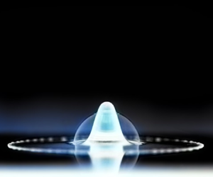
In addition to the impingement of regular droplets on a surface, there are special cases that deal with hollow droplets containing void inside their volume (figure 1) or droplets containing two different liquids (compound droplets) (Blanken et al. Reference Blanken, Saleem, Thoraval and Antonini2021). The interaction of hollow droplets with a rigid wall occurs in the fields of controllable biomedicine (Wang et al. Reference Wang, Kang, Lee, Luo, Huang and Yeh2012; Mountford, Thomas & Borden Reference Mountford, Thomas and Borden2015; Rapoport Reference Rapoport2016; Sheeran et al. Reference Sheeran, Daghighi, Yoo, Williams, Cherin, Foster and Burns2016), thermal spray coating (Solonenko, Gulyaev & Smirnov Reference Solonenko, Gulyaev and Smirnov2008; Solonenko et al. Reference Solonenko, Nishiyama, Smirnov, Takana and Jang2015), cavitation (Moezzi-Rafie & Nasiri Reference Moezzi-Rafie and Nasiri2018) and lithotripsy. It should be mentioned that the hollow droplet is different than the bubble entrapment after droplet impact on a liquid pool (Tran et al. Reference Tran, de Maleprade, Sun and Lohse2013) or a surface (Hicks & Purvis Reference Hicks and Purvis2010; Zhao, De Jong & van der Meer Reference Zhao, De Jong and van der Meer2019).

Figure 1. Impingement of a hollow water droplet with a speed of surface  ${U_o} = 3.6\ \textrm{m}\ {\textrm{s}^{ - 1}}$ on an aluminium surface (Nasiri et al. Reference Nasiri, Amini, Moreau and Dolatabadi2021).
Although there are thousands of publications on dense droplet impingement, only a few studies have focused on the impact of a hollow droplet on a surface. Solonenko et al. studied the deposition of hollow sphere yttria-stabilised-zirconia (YSZ) during plasma thermal spray coating (Solonenko et al. Reference Solonenko, Gulyaev and Smirnov2008). They noticed fundamental differences in the behaviour of dense and hollow droplets during impact on a surface. It was shown that zirconia splats produced by the collision of hollow sphere particles to the substrate have a more stable character compared to splats formed by dense droplets. The reason behind this is not fully understood yet. Blanken et al. have reviewed studies on compound droplets, and have addressed the fundamental aspects of compound drop impact and discussed the current challenges related to experimental testing and numerical simulation of multiphase fluid systems (Blanken et al. Reference Blanken, Saleem, Thoraval and Antonini2021).
Gulyaev et al. investigated the impingement of hollow glycerin droplets. They observed the formation of a liquid counter-jet due to the hollow droplet impact on a surface for the first time (Gulyaev & Solonenko Reference Gulyaev and Solonenko2013). They also developed an integral-differential equation for hollow droplet flattening for low and high Eu cases. For high Eu, they simplify their equation into two equations based on droplet initial condition including infinity Re and very low We, or low Re and infinity We numbers (Gulyaev et al. Reference Gulyaev, Solonenko, Gulyaev and Smirnov2009; Gulyaev & Solonenko Reference Gulyaev and Solonenko2013).
Kumar and Gu applied the volume of fluid (VOF) method to incompressible Navier–Stokes equations and numerically investigated the flattening and solidification of a hollow droplet in plasma thermal spraying conditions (Kumar & Gu Reference Kumar and Gu2012). A modified VOF-based numerical method was applied by Safaei et al. to consider the effects of gas compressibility along with liquid solidification during the high-velocity impact of a hollow droplet (Safaei et al. Reference Safaei, Emami, Jazi and Mostaghimi2017). Wei & Thoraval (Reference Wei and Thoraval2021) also have performed numerical simulation of hollow droplet flattening impacting a solid surface to predict maximum spreading of a hollow droplet. In addition, there are other studies investigating hollow droplet behaviour after impact on a liquid pool (Deka et al. Reference Deka, Biswas, Sahu, Kulkarni and Dalal2019; Zhu et al. Reference Zhu, Kherbeche, Feng and Thoraval2020).
Moreover, a combined level set-volume of fluid (CLSVOF) numerical simulation was performed to study the effects of gas pressure on the flattening of the hollow droplet (Li, Zhang & Zheng Reference Li, Zhang and Zheng2019). Recently, the authors have conducted experimental and numerical investigations on the flattening of the hollow droplet and described its differences with the flattening of the dense droplet (Nasiri et al. Reference Nasiri, Amini, Moreau and Dolatabadi2021). It was shown that even though a portion of liquid of hollow droplet leaves the surface as counter-jet, the maximum spreading diameter of the hollow droplet is similar to that of the dense droplet with the same mass (Nasiri et al. Reference Nasiri, Amini, Moreau and Dolatabadi2021).
Generally, when a hollow droplet impacts a surface, it spreads and simultaneously a counter-jet takes shape inside the entrapped bubble (figure 1) (Nasiri et al. Reference Nasiri, Amini, Moreau and Dolatabadi2021). The counter-jet grows during the flattening of the hollow droplet, passes through the trapped bubble and compresses the air inside the bubble, leading to bubble rupture. This bubble rupture induces perturbations on the surface of the spreading droplet. The counter-jet grows and depending on the impact velocity of the hollow droplet, breaks up and detaches from the surface or recoils towards the surface.
To better understand the flattening process of a hollow droplet, in this work, a comprehensive experimental and numerical study is performed on hollow water droplets impacting a surface. The effects of bubble size and location on spreading diameter, counter-jet shape and splat thickness are investigated. Additionally, a theoretical study is performed to calculate the maximum spreading of a hollow droplet after impact on a surface.
2. Experiment set-up and measurements
The schematic of the experimental set-up is shown in figure 2. Impact experiments were performed at room temperature with 40 % relative humidity in the ambient environment. The droplets were injected from a needle with an inner diameter of 2.18 mm connected to a syringe pump at a flow rate of 50 μL min−1 (Pico Plus, Harvard Apparatus). Another needle was implemented inside the main needle to inject air into the liquid droplet, where the tips of both needles were located in a line. When a droplet started to form at the tip of the liquid needle, the second needle was used to inject an air bubble into the droplet. The gas injection process was done with constant flow rate, manually. Liquid and air injection were continuous until further increment in the droplet weight caused the hollow droplet detachment from the needle tip. It should be mentioned that the proposed set-up is capable of producing hollow droplets, but the size of hollow droplets produced vary significantly and the experiments had to be repeated several times to produce a hollow droplet with almost exact sizes.

Figure 2. Schematic of the experimental set-up of hollow droplet impact.
The height of the needle above the surface was varied between 50 and 700 mm, resulting in impact velocities ranging from 0.5 to 3.6 m s−1. A high-speed camera (Phantom v711, Vision Research) recorded the impacting droplets. The process was illuminated by a lamp enabling filming the process at a rate of 5000 fps and an exposure time of 30 μs. The video signal was recorded in the memory of a PC, and the images were analysed using ImageJ software (version 1.46, National Institutes of Health, Bethesda, MD).
The apparent, advancing and receding contact angles of water droplet on the aluminium surface were measured as 85°±2°, 94°±2° and 65°±2°, respectively. The fall of hollow droplets from 50 mm height was recorded on the video camera, and the spread droplets were weighed on a balance accurate to 0.05 mg. From the taken images, the outer diameter of the droplet  $({D_h})$ and the diameter of the bubble
  $({D_{b - image}})$ were measured. Considering the density of water and calculating the total volume of the hollow droplet, the actual diameter of the bubble
  $({D_b})$ was evaluated. Measurements show that, due to the fisheye effect,
  ${D_{b - image}}$ is not equal to
  ${D_b}$ and it needs to be corrected. These measurements were repeated for ten droplets and at the end, the following correlation was derived to calculate the actual size of the bubble from token images (Nasiri et al. Reference Nasiri, Amini, Moreau and Dolatabadi2021):
 \begin{equation}{D_b} = \; 0.86\times {D_{b - image}}.\end{equation}
The details of the hollow droplet size calculations and experimental set-up are presented in the previously published article of Nasiri et al. (Reference Nasiri, Amini, Moreau and Dolatabadi2021). To report the experimental data, ten similar hollow droplets with less than 10 % standard deviation in the size of droplet and bubble were measured.
3. Numerical analysis
To explain the experiments and provide a better understanding of the reasoning behind the formation and detachment of liquid counter-jet, a numerical model has been used to solve compressible continuum equations for the drop flattening on a surface. Figure 3 shows schematics of a hollow droplet impacting a flat surface. Several parameters are defined to characterise this process. The main geometrical parameters are the initial diameter of the hollow droplet  $({D_h})$ and the initial diameter of the bubble inside the hollow droplet
  $({D_b})$, which are shown in figure 3(a). The flattening of a hollow droplet is schematically shown in figure 3(c) showing the related parameters of counter-jet diameter
  $({D_{cj}})$, counter-jet height
  $({h_{cj}})$, counter-jet velocity
  $({U_{cj}})$, spreading diameter (D), splat height
  $(h)$ and spreading velocity
  $({U_R})$. Equivalent diameter
  $({D_{eq}})$ of a hollow droplet is defined as the diameter of a dense droplet with the same weight (figure 3b). These diameters are related to each other by the definition of
  $\alpha ,\beta $ parameters as
 \begin{equation}{D_h} = \alpha {D_{eq}},\quad {D_b} = \beta {D_{eq}}.\end{equation}
From (3.1), it can easily be concluded that  ${\alpha ^3} - {\beta ^3} = 1$. To study the impact process, a hollow droplet with a size of
  ${D_h} = 5.6\ \textrm{mm},\;{D_b} = 4.5\ \textrm{mm}$ and
  ${D_{eq}} = 4.4\ \textrm{mm}$ is simulated at different velocities. The hollow droplet vertically impacts a flat aluminium surface with an initial temperature of 300 K. The ambient pressure and temperature are 1 atm and 300, respectively. The properties of fluids used in this simulation are presented in table 1.

Figure 3. Geometrical model of a droplet impacting a flat surface: (a) hollow droplet before and after impact; (b) dense droplet before and after impact; (c) hollow droplet spreading after impact.
Table 1. Properties of water and air at T = 300 K.

Due to the symmetry of the process, a 2-D-axisymmetric domain was used to simulate the droplet impact on a flat surface. The computational domain and boundary conditions are shown in figure 4. The behaviour of a hollow droplet, including spreading and bubble ruptures, was captured in the simulations with grid numbers from 208 000 to 1 200 000. The results were validated with extracted experimental data. Compromising the accuracy and time, a structured grid with total grid numbers of 340 000 was chosen to simulate all the cases. The results for mesh independency of the solution have been reported in the previous study of the authors (Nasiri et al. Reference Nasiri, Amini, Moreau and Dolatabadi2021). With the current grid distribution, approximately 100 cells per diameter exist inside the hollow droplet before the impact. It should be mentioned that cells were more concentrated near the symmetry axis and along the bottom boundary, the cells are fine and uniform at the impact location (around 0.125 mm) and the grid distribution is constant at different time steps.

Figure 4. Computational domain and boundary conditions of the specified problem.
The no-slip boundary condition is applied on the bottom surface and the pressure boundary condition is zero gradient. The dynamic contact angle is used to simulate the liquid motion on the bottom wall. The apparent, advancing and receding contact angles for water on an aluminium surface are reported in table 2. For the other side of the domain, velocity boundary conditions are assumed to be zero gradient while the pressure is atmospheric pressure.
Table 2. Measured contact angles of water on different surfaces.
The mass, momentum and energy equations are the governing equations to be solved to simulate hollow droplet flattening with the VOF method as
 \begin{gather}\frac{{\partial \rho }}{{\partial t}} + {\nabla }\boldsymbol{\cdot }(\rho \; \boldsymbol{U}) = 0,\end{gather}
 \begin{gather}\frac{{\partial (\rho \boldsymbol{U})}}{{\partial t}} + {\nabla }\boldsymbol{\cdot }(\rho \boldsymbol{UU}) = \; - \boldsymbol{\nabla }p + \rho \boldsymbol{g} + \boldsymbol{\nabla }\boldsymbol{\cdot }\{ \mu [{\nabla }\boldsymbol{U} + {({\nabla }\boldsymbol{U})^T}]\} + {\boldsymbol{F}_{vol}}.\end{gather}
 \begin{gather}\frac{{\partial (\rho {C_p}T)}}{{\partial t}} + \boldsymbol{\nabla }\boldsymbol{\cdot }(\rho {C_p}\boldsymbol{U}T) = {\nabla }\boldsymbol{\cdot }(k{\nabla }T) + \frac{{\partial p}}{{\partial t}} - \left( {\frac{{\partial \rho K}}{{\partial t}} + \boldsymbol{\nabla }\boldsymbol{\cdot }(\rho \boldsymbol{U}K)} \right),\end{gather}
where  $\rho $,
  $\boldsymbol{U}$, P,
  $\boldsymbol{g}$, K and
  ${C_p}$ are mixture density, velocity field, pressure, gravitational acceleration, the kinetic energy of fluid, and the specific heat, respectively. Surface tension is considered as a source term
  $({\boldsymbol{F}_{vol}})$ and can be calculated using the Brackbill method (Brackbill, Kothe & Zemach Reference Brackbill, Kothe and Zemach1992). To solve momentum equations correctly, the pressure field can be calculated from the following equation (Miller et al. Reference Miller, Jasak, Boger, Paterson and Nedungadi2013):
 \begin{equation}\left( {\gamma
\frac{{{\varPsi_l}}}{{{\rho_l}}} + (1 - \gamma
)\frac{{{\varPsi_g}}}{{{\rho_g}}}} \right)\left[
{\frac{{\partial p}}{{\partial t}} +
\boldsymbol{U}\boldsymbol{\cdot }\boldsymbol{\nabla }p}
\right] + \boldsymbol{\nabla }\boldsymbol{\cdot
}\boldsymbol{U} = 0,\end{equation}
\begin{equation}\left( {\gamma
\frac{{{\varPsi_l}}}{{{\rho_l}}} + (1 - \gamma
)\frac{{{\varPsi_g}}}{{{\rho_g}}}} \right)\left[
{\frac{{\partial p}}{{\partial t}} +
\boldsymbol{U}\boldsymbol{\cdot }\boldsymbol{\nabla }p}
\right] + \boldsymbol{\nabla }\boldsymbol{\cdot
}\boldsymbol{U} = 0,\end{equation}
where  ${\varPsi _l}$,
  ${\varPsi _g}$,
  ${\rho _l}$,
  ${\rho _g}$ and
  $\gamma $ are the compressibility and the density of liquid and gas, and the liquid–gas volume fraction, respectively. Defining compressibility as
  $\varPsi = \partial \rho /\partial P$ based on the ideal gas equation of state, gas compressibility and liquid compressibility take the forms of
 \begin{equation}{\varPsi _g} = \; \frac{1}{{zRT}}\; ,\quad {\varPsi _l} = \; \frac{1}{{{a^2}}},\end{equation}
where z represents compressibility factor with the isothermal equation of state assumption. Parameter a represents sound velocity in the liquid. It should be noted that regarding the impact velocity of the hollow droplet (1–6 m s−1), the compressibility does not play a role in the dynamic of hollow droplet flattening and can be ignored.
To track the interface of two fluids, the VOF equation is used (Miller et al. Reference Miller, Jasak, Boger, Paterson and Nedungadi2013):
 \begin{equation}
\left. {\begin{array}{*{20}{c@{}}} {\dfrac{{\partial (\gamma
)}}{{\partial t}} + \boldsymbol{\nabla }\boldsymbol{\cdot
}(\gamma \boldsymbol{U}) = \dfrac{{ - \gamma
{\varPsi_l}}}{{{\rho_l}}}\dfrac{{\textrm{D}p}}{{\textrm{D}t}}
= \gamma (1 - \gamma )\zeta + \gamma \boldsymbol{\nabla
}\boldsymbol{\cdot }(\boldsymbol{U})}\\
{\zeta = \left( {\dfrac{{{\varPsi_l}}}{{{\rho_l}}} +
\dfrac{{{\varPsi_g}}}{{{\rho_g}}}}
\right)\dfrac{{\textrm{D}p}}{{\textrm{D}t}}} \end{array}}
\right\}.\end{equation}
\begin{equation}
\left. {\begin{array}{*{20}{c@{}}} {\dfrac{{\partial (\gamma
)}}{{\partial t}} + \boldsymbol{\nabla }\boldsymbol{\cdot
}(\gamma \boldsymbol{U}) = \dfrac{{ - \gamma
{\varPsi_l}}}{{{\rho_l}}}\dfrac{{\textrm{D}p}}{{\textrm{D}t}}
= \gamma (1 - \gamma )\zeta + \gamma \boldsymbol{\nabla
}\boldsymbol{\cdot }(\boldsymbol{U})}\\
{\zeta = \left( {\dfrac{{{\varPsi_l}}}{{{\rho_l}}} +
\dfrac{{{\varPsi_g}}}{{{\rho_g}}}}
\right)\dfrac{{\textrm{D}p}}{{\textrm{D}t}}} \end{array}}
\right\}.\end{equation}
By solving the above equation, the value of  $\gamma $ can be obtained for each computational cell. The cell is occupied by liquid if
  $\gamma = 1$, whereas the cell is occupied with gas if
  $\gamma = 0$. Any value in the range of
  $0 < \gamma < 1$ indicates that the cell contains a liquid–gas interface. Once
  $\gamma $ has been determined, the surface tension force can be calculated as follows (Brackbill et al. Reference Brackbill, Kothe and Zemach1992):
 \begin{equation}
{\boldsymbol{F}_{vol}} = \sigma \kappa ({\nabla }\gamma ),\quad \kappa =-
{\nabla }\boldsymbol{\cdot }\left(
{\frac{{{\nabla }\gamma }}{{|{\nabla }\gamma |}}} \right),\end{equation}
\begin{equation}
{\boldsymbol{F}_{vol}} = \sigma \kappa ({\nabla }\gamma ),\quad \kappa =-
{\nabla }\boldsymbol{\cdot }\left(
{\frac{{{\nabla }\gamma }}{{|{\nabla }\gamma |}}} \right),\end{equation}
where  $\sigma $ and
  $\kappa $ represent the surface tension of the liquid and the surface curvature, respectively, and
  $\nabla \gamma $ is a continuous function that is zero everywhere in the domain except for the transitional area at the interface. The mixture properties can be expressed as
 \begin{gather}\mu = \gamma {\mu _l} + (1 - \gamma ){\mu _g},\end{gather}
 \begin{gather}\rho = \gamma {\rho _l} + (1 - \gamma ){\rho _g},\end{gather}
 \begin{gather}k = \gamma {k_l} + (1 - \gamma ){k_g},\end{gather}
 \begin{gather}{c_p} = \gamma {c_{p,l}} + (1 - \gamma ){c_{p,g}}.\end{gather}
To optimise the computational time, an adaptive time step control feature was applied. This controller, which keeps the solution stable, was adjusted based on the Courant–Friedrichs–Lewy (CFL) number  $(Co = {U_i}\Delta t/\Delta x)$ at the beginning of the time iteration loop. Using the values of the velocity of the phase fractions and
  $\Delta t$ from the previous time step, the maximum local CFL number
  $(C{o_0})$ was calculated, and a new time step was iteratively initiated as
 \begin{equation}\Delta t = min\left\{ {\frac{{C{o_{max}}}}{{C{o_0}}}\Delta {t_0};\left( {1 + {\lambda_1}\frac{{C{o_{max}}}}{{C{o_0}}}} \right)\Delta {t_0};{\lambda_2}\Delta {t_0};\Delta {t_{max}}} \right\},\end{equation}
where  $C{o_{max}}$ and
  $\Delta {t_{max}}$ prescribe values for the CFL number and time step, respectively (Yeganehdoust et al. Reference Yeganehdoust, Attarzadeh, Karimfazli and Dolatabadi2020). It should be noted that codes of OpenFOAM open-source solver have been used to simulate the droplet flattening.
4. Results and discussion
After impact, a dense droplet flattens on the surface until reaching its maximum spreading diameter and then retracts towards the centre (figure 5a). This retracting liquid results in an oscillating bulk of water on the surface until it stabilises. There is no liquid detachment from the surface during the whole process. In contrast, the behaviour of a hollow droplet impact is different (figure 5b); while a hollow droplet spreads on the surface, a counter-jet takes shape in the axial direction.

Figure 5. Selected snapshots showing droplet impact on an aluminium surface: (a) dense water droplet with  ${D_{eq}} = 4.4\ \textrm{mm}$ impacting at
  ${U_0} = 3.6\ \textrm{m}\ {\textrm{s}^{ - 1}}(We = 790,\;Ca = 0.0016)$; (b) hollow water droplet with
  ${D_h} = 5.6\ \textrm{mm},\;{D_b} = 4.5\ \textrm{mm}$ and
  ${D_{eq}} = 4.4\ \textrm{mm}$ impacting at
  ${U_0} = 3.6\ \textrm{m}\ {\textrm{s}^{ - 1}}(We = 790,\;Ca = 0.0016)$; (c) hollow water droplet with
  ${D_h} = 5.6\ \textrm{mm},\;{D_b} = 4.5\ \textrm{mm}$ and
  ${D_{eq}} = 4.4\ \textrm{mm}$ impacting at
  ${U_0} = 1.0\ \textrm{m}\ {\textrm{s}^{ - 1}} (We = 60,\;Ca = 0.0016)$.
This counter-jet crosses the upper shell of the entrapped bubble. When the hollow droplet reaches its maximum spreading diameter, the central counter-jet is still growing and eventually breaks away from the spreading liquid. As a result of this breakup, a portion of liquid mass detaches from the surface while the remaining liquid stabilises and takes a semicircular shape similar to the dense droplet.
When a dense droplet impacts a surface, the pressure of the liquid at the contact point increases. This high pressure gradually decreases inside the droplet. The liquid located at this high-pressure region intends to move to regions with lower pressure. Nevertheless, the liquid cannot recoil and move upward because of the pressure gradient inside the droplet. Therefore, the liquid can only spread in the radial direction and consequently, the dense droplet flattens on the surface. As a result, the kinetic and surface energies of the droplet before impact convert to the surface energy of the spreading droplet and dissipate through viscosity. The equilibrium between these energies determines the spreading diameter of the droplet (Nasiri et al. Reference Nasiri, Amini, Moreau and Dolatabadi2021).
However, when a hollow droplet impacts a surface, the same high-pressure region at the impact location can be observed. The only difference is that this high-pressure region does not gradually decrease inside the droplet. Instead, there is a pressure gap between the high-pressure region of the droplet with the upper half of the droplet. This pressure gap allows the pressurised liquid to move upward in addition to spreading on the surface. Thereupon, a counter-jet forms on the surface as the hollow droplet flattens. Considering the equilibrium between the energy before and after impact, the spreading portion of the hollow droplet has less energy to spread on the surface compared to the dense droplet. Therefore, a smaller spreading diameter is observed for the hollow droplet in comparison to the dense droplet. It should be noted that, as a result of the impact, the pressure inside the bubble increases (Nasiri et al. Reference Nasiri, Amini, Moreau and Dolatabadi2021).
Many parameters affect the behaviour of a hollow droplet after impact on the surface, including droplet velocity (figure 5c), type of the liquid, size and location of the entrapped bubble. For instance, at hollow droplet impact with low velocity or high viscosity, which can be distinguished as low  $Re$ number, the spreading diameter of the hollow droplet is lower than that of hollow droplet impact at high
  $Re$ numbers. This is due to lower kinetic energy, which can be dissipated by a higher ratio of viscous force, surface tension and gravitation force. The other difference concerns the formation of the counter-jet. Even though the counter-jet forms even at impacts with low
  $Re$ numbers, the length of the counter-jet is small, there is no detachment and the counter-jet returns to the spreading portion of the liquid. Therefore, the effects of these parameters on the behaviour of the hollow droplet are studied through a detailed numerical investigation.
Figure 6 shows snapshots of the simulation of a hollow droplet impacting on a surface with  ${U_0} = 3.6\ \textrm{m}\ {\textrm{s}^{ - 1}}$. As can be seen, the flattening behaviour of the hollow droplet predicted by the numerical simulation is similar to the captured experimental photos. The only difference is the fingering phenomenon in the experimental images, which was not captured due to the 2-D-axisymmetric assumption in the numerical simulations.

Figure 6. Selected snapshots of experimental images and numerical simulation for a hollow water droplet with  ${D_h} = 5.6\ \textrm{mm},\;{D_b} = 4.5\ \textrm{mm},\;{D_{eq}} = 4.4\ \textrm{mm}$ impacting on an aluminium surface at
  $Re = 17\;760$ and
  $We = 790$ (corresponding to
  $U = 3.6\ \textrm{m}\ {\textrm{s}^{ - 1}}\; $). The experimental images are shown to be compared with the results of the numerical simulation.
Moreover, two critical parameters obtained by the numerical simulation, i.e. the spreading diameter and the counter-jet height of the hollow droplet after impact, are compared with the measured experimental data in figure 7. As is shown, the numerical results are in good agreement with the experimental data at different velocities.

Figure 7. Characteristics of a hollow droplet with  ${D_h} = 5.6\ \textrm{mm},\;{D_b} = 4.5\ \textrm{mm}$,
  ${D_{eq}} = 4.4\ \textrm{mm}$ and
  $Ca = 0.0016$ impacting at different velocities: (a) spreading diameter
  $(D_s^\ast= {D_s}/{D_{eq}})$ versus time
 $({t^\ast } = t{U_0}/{D_{eq}})$; (b) counter-jet height
  $(h_{cj}^\ast= {h_{cj}}/{D_{eq}})$ versus time.
4.1. Hollow droplet impact at different velocities
Figure 8 shows snapshots of the numerical simulations of the hollow droplet at different velocities. The spreading and the counter-jet formation is captured at all different velocities. By increasing the impact velocity, the length of the counter-jet becomes longer while its width gets thinner. In addition, the spreading diameter is increased by the impact velocity of the hollow droplet.

Figure 8. Selected snapshots of numerical simulation of a hollow water droplet with  ${D_h} = 5.6\ \textrm{mm}, {D_b} = 4.5\ \textrm{mm},\;{D_{eq}} = 4.4\ \textrm{mm}$ and
  $Ca = 0.0016$ impacting a surface at different Weber numbers: (a)
  $\; {U_0} = 1.8\ \textrm{m}\ {\textrm{s}^{ - 1}}(We = 198)$; (b)
  ${U_0} = 2.4\ \textrm{m}\ {\textrm{s}^{ - 1}}(We = 350)$; (c)
  ${U_0} = 3.6\ \textrm{m}\ {\textrm{s}^{ - 1}}(We = 790)$; (d)
  ${U_0} = 4.8\ \textrm{m}\ {\textrm{s}^{ - 1}}(We = 1410)$.
The characteristics of the hollow droplet impingement on a surface are demonstrated in figures 9 and 10. Dimensionless numbers are defined to provide more comprehensive information. Figure 9(a) shows the dimensionless spreading diameter  $(D_s^\ast= {D_s}/{D_{eq}})$ of a hollow droplet during dimensionless time
  $({t^\ast } = t{U_0}/{D_{eq}})$ at different impact velocities. The droplet spreading increases with droplet impact velocity
  $({U_0})$ until it reaches its maximum value, then recoils and forms a semicircular shape.

Figure 9. Numerical simulation results of characteristics of a hollow droplet with  ${D_h} = 5.6\ \textrm{mm}, {D_b} = 4.5\ \textrm{mm}$,
  ${D_{eq}} = 4.4\ \textrm{mm}$ and
  $Ca = 0.0016$ impacting at different velocities: (a) spreading diameter
  $(D_s^\ast= {D_s}/{D_{eq}})$ versus time
  $({t^\ast } = t{U_0}/{D_{eq}})$; (b) counter-jet height
  $(h_{cj}^\ast= {h_{cj}}/{D_{eq}})$ versus time.

Figure 10. Numerical simulation results of characteristics of hollow droplet  ${D_h} = 5.6\ \textrm{mm},\;{D_b} = 4.5\ \textrm{mm}$ and
  ${D_{eq}} = 4.4\ \textrm{mm}$ impacting at different velocities: (a) velocity of the counter-jet
  $(U_{cj}^\ast= {U_{cj}}/{U_0})\; $versus time
  $({t^\ast } = t{U_0}/{D_{eq}})$; (b) counter-jet volume
  $(V_{cj}^\ast= {V_{cj}}/[\alpha \beta {V_{eq}}])$ versus droplet impact Reynolds number at the maximum spreading time.
The dimensionless counter-jet height  $(h_{cj}^\ast= {h_{cj}}/{D_{eq}})$ against dimensionless time is demonstrated in figure 9(b). The height of the counter-jet grows until it reaches a maximum value and then starts to fall at low impact velocities. However, the height of the counter-jet increases permanently until it detaches from the surface at high impact velocities. The slope of counter-jet height against time at different droplet impact velocities is shown here. Clearly, a similar slope at different impact velocities can be observed, especially at initial instances of the counter-jet formation. Then, the slope decreases, resulting from dissipation of energy during counter-jet formation and progress. The decrement is more evident at low impact velocities, while the slope is almost linear during counter-jet progress, especially at high impact velocities.
Figure 10(a) shows the dimensionless counter-jet velocity  $(U_{cj}^\ast= {U_{cj}}/{U_0})\; $ against dimensionless time
  $({t^\ast })$ at different impact velocities. At the impact of the hollow droplet on the surface, a counter-jet forms, which moves perpendicular to the surface. The velocity of the counter-jet increases with progress in time. This increment continues until a maximum velocity. The maximum velocity point occurs before the penetration of the counter-jet into the upper shell of the entrapped bubble (figure 11). At low
  $Re$ number, the counter-jet retracts towards the surface after reaching a peak which is shown by negative velocity in figure 10(a). However, at high
  $Re$ number, the counter-jet develops with a constant velocity
  $(U_{cj}^\ast= 0.4)$ until it detaches from the surface.

Figure 11. Snapshots of the counter-jet penetration into the upper shell of the bubble for a hollow droplet with  ${D_H} = 5.6\ \textrm{mm}$ and
  ${D_B} = 2.8\ \textrm{mm}$ impacting at
  $Re = 17\;760$ and
  $We = 790\; $(corresponding to
 $\; \; U = 3.6\ \textrm{m}\ {\textrm{s}^{ - 1}}$).
The dimensionless volume of the counter-jet  $(V_{cj}^\ast= {V_{cj}}/[\alpha \beta {V_{eq}}])$ at the maximum spreading time is demonstrated in figure 10(b) for different velocities. This volume includes the liquid pillar from the surface which has a positive velocity in the Z direction.
As it can be seen, the volume of the counter-jet is almost  ${V_{cj}} = 0.3\alpha \beta {V_{eq}}$ at the maximum spreading, no matter the hollow droplet impact velocity.
4.2. Bubble size
The other parameter that affects the hollow droplet impact characteristics is the size of the entrapped bubble. Figure 12 shows snapshots of hollow droplets impact with different bubble sizes. The formation of the counter-jet is the same for all droplets. Nevertheless, the counter-jet shape is different. As the size of entrapped bubble increases, the size of the counter-jet grows. In addition, there are oscillations on the counter-jet's surface for hollow droplets with small, trapped bubbles, leading to faster breakup and detachment of the counter-jet from the surface compared to hollow droplets with larger bubbles.

Figure 12. Selected snapshots showing hollow droplet impact at  ${U_0} = 3.6\ \textrm{m}\ {\textrm{s}^{ - 1}}$ and
  ${D_{eq}} = 4.54\ \textrm{mm} (We = 790,\;Ca = 0.0016\textrm{)}$ with different bubble sizes: (a)
  ${D_h} = 4.6\ \textrm{mm},\;{D_b} = 0.96\ \textrm{mm}$; (b)
  ${D_h} = 4.84\ \textrm{mm}, {D_b} = 2.7\ \textrm{mm}$; and (c)
  ${D_h} = 5.4\ \textrm{mm},\;{D_b} = 4.0\ \textrm{mm}$.
To enable an accurate comparison between hollow droplet impacts with different bubble sizes, numerical simulations are performed on hollow droplets with a diameter of  ${D_h} = 5.6\ \textrm{mm}$ and different bubble sizes impacting on a surface with velocity
  ${U_0} = 3.6\ \textrm{m}\ {\textrm{s}^{ - 1}}$. Hollow droplets with constant outer diameter
  $({D_h} = 5.6\ \textrm{mm})$ and different bubble sizes
  $({D_b})$ are considered where the hollowness ratio
  $(\beta /\alpha )$ varies from 0.25 to 0.85. Snapshots of numerical results for hollow droplet impact with different bubble locations are presented in Appendix A.
Generally, hollow droplets with different bubble sizes have similar behaviour after impact on the surface. As the size of the entrapped bubble decreases, the maximum spreading diameter of the hollow droplet increases due to higher mass of the droplet, which impacts the surface (figure 13a). It should be mentioned that in figure 13(a), the spreading diameter is non-dimensional using an equivalent diameter of each specific droplet and can be calculated by (3.1).

Figure 13. Numerical simulation results of the spreading characteristics of a hollow droplet  ${D_h} = 5.6\ \textrm{mm}\ (Ca = 0.0016)$ with different bubble sizes impacting on a surface at
  ${U_0} = 3.6\ \textrm{m}\ {\textrm{s}^{ - 1}}$: (a) spreading diameter
  $(D_s^\ast= {D_s}/{D_{eq}})$ versus time
  $({t^\ast } = t{U_0}/{D_{eq}})$; (b) counter-jet height
  $(h_{cj}^\ast= {h_{cj}}/{D_{eq}})$ versus time.
The other parameter which is influenced by the size of the bubble is the counter-jet height. As is shown in figure 13(b), the height of the counter-jet increases over time with a similar slope for all hollow droplets except for hollow droplets with hollowness ratio parameter  $\beta /\alpha < 0.35$. This is due to the higher thickness of the bubble shell for low-hollowness-ratio droplets, which reduces the counter-jet energy during passing through the upper shell of the bubble. Nevertheless, the maximum height of the counter-jet at each time does not belong to the hollow droplet with the smallest or largest bubble. There is an optimum value for the size of the bubble, which leads to the highest counter-jet length, which is Dh = 4.0 mm and can be calculated for any hollow droplet with the optimised hollowness ratio parameter
  ${(\beta /\alpha )^\ast } = 0.71$.
Figure 14(a) shows the dimensionless velocity of the counter-jet during the dimensionless time. The trend of the counter-jet velocity is similar to what was seen in figure 10(a). After formation, the counter-jet velocity increases until it reaches the upper shell of the bubble. For hollow droplets with  $\beta /\alpha > 0.35$, the counter-jet passes through this shell and loses a portion of its kinetic energy and continues with an average velocity of
  $U_{cj}^\ast= 0.4$. This value is less for hollow droplets with
  $\beta /\alpha < 0.35$, which justifies lower slopes of the counter-jet heights of these droplets in figure 13(b). The other issue is the counter-jet level falling after the first peak. It is shown that as the hollowness ratio
  $(\beta /\alpha )$ increases, the minimum point decreases and for the hollow droplets with highest hollowness ratio
  $(\beta /\alpha )$, the minimum point peak is vanished.

Figure 14. Numerical simulation results of the spreading characteristics of a hollow droplet  ${D_h} = 5.6\ \textrm{mm}$
  $(Ca = 0.0016)$ with different bubble sizes impacting on the surface at
  ${U_0} = 3.6\ \textrm{m}\ {\textrm{s}^{ - 1}}$: (a) velocity of the counter-jet
  $(U_{cj}^\ast= {U_{cj}}/{U_0})\; $versus time
  $({t^\ast } = t{U_0}/{D_{eq}})$; (b) counter-jet volume
  $(Vol_{cj}^\ast= Vo{l_{cj}}/[\alpha \beta \,Vo{l_{eq}}])\; $ versus hollowness ratio at maximum spreading time.
The counter-jet velocity shows two picks during counter-jet evolution. The first picks occurs when the counter-jet penetrates the bubble and reaches upper shell of the bubble. At this point, the liquid in the upper portion of the hollow droplet damps the counter-jet motion and reduces the counter-jet velocity. This pick has been observed in all cases and it is more severe in case with low hollowness ratio, as the counter-jet has to pass a thicker shell.
However, there is a second pick that only has been seen in cases with lower hollowness ratio. This pick can be due to the liquid portion which is still falling after the bubble collapse or because of bubble rupture which induces velocity to the counter-jet. In the case of hollow droplets with low hollowness (thicker bubble shell), when the bubble ruptures, the liquid shell moves fast towards the substrate as a ligament and joins the flattening liquid. This liquid mass increases the counter-jet velocity again until a point where the gravity decelerates the counter-jet. As the hollowness ratio increases, the bubble shell becomes thinner. In droplets with high hollowness ratio, the bubble explodes and a thin liquid shell disperse around it which cannot significantly change the counter-jet velocity.
The dimensionless counter-jet volume at the maximum spreading time is demonstrated in figure 14(b). The size of the entrapped bubble can affect the shape, and the volume of the counter-jet at it was reported in figure 12. Nevertheless, the dimensionless volume of the counter-jet is in the range of  $0.26 < Vol_{cj}^\ast < 0.34$. This variation decreases for hollow droplets with high hollowness ratio and reaches a constant value of
  $Vol_{cj}^\ast= 0.3$ or
  $Vo{l_{cj}} = 0.3\alpha \beta \,Vo{l_{eq}}$.
Plasma spraying is one of the main applications of hollow droplets due to the possibility of producing coatings with higher porosity. This increased porosity is a result of increased roughness on the solidified splats. Hence, the effect of bubble size on the roughness of the splat at maximum spreading is demonstrated in figure 15. In addition to differences in the shape of the counter-jet and the spreading diameter of hollow droplets with different bubble sizes, which can be seen in figure 14, the splat surface roughness is another parameter that can distinguish the effect of bubble size (figure 15b). As can be seen, droplets with a higher hollowness ratio have a rougher surface than the hollow droplets with a lower hollowness ratio. This is due to a thinner bubble shell of hollow droplets with a high hollowness ratio which can be affected by the bubble explosion that induces more strong perturbations to the surface of the splat.

Figure 15. Numerical simulation results of counter-jet height versus spreading radius of a hollow droplet  ${D_h} = 5.6\ \textrm{mm}\ (Ca = 0.0016\textrm{)}\; $with different bubble sizes impacting on a surface at
  ${U_0} = 3.6\ \textrm{m}\ {\textrm{s}^{ - 1}}$ at maximum spreading time.
The other issue that is important to note is that when a droplet impacts a surface, a small portion of air entraps underneath the droplet that cannot be washed off by the liquid inertia due to the axisymmetric definition of the problem (Nasiri, Dolatabadi & Moreau Reference Nasiri, Dolatabadi and Moreau2022).
4.3. Bubble location
The location of the entrapped bubble inside the hollow droplet plays some roles in the outcome of the droplet impact, as demonstrated in figure 16.

Figure 16. Selected snapshots showing the spread of a hollow water droplet with different bubble locations impact at  ${U_0} = 3.6\ \textrm{m}\ {\textrm{s}^{ - 1}}$ with: (a)
  ${D_h} = 4.8\ \textrm{mm},\;{D_b} = 3.1\ \textrm{mm}$ and
  ${D_{eq}} = 4.3\ \textrm{mm}$,
  ${\delta ^\ast } = 0.14$; (b)
  ${D_h} = 4.92\ \textrm{mm},\;{D_b} = 3.44\ \textrm{mm}$ and
  ${D_{eq}} = 4.4\ \textrm{mm}$,
  ${\delta ^\ast } = 0.0$.
Four different cases are numerically simulated to investigate the effect of bubble location accurately (figure 17). In the first case, the bubble is located at the centre, and in the last one, it is located at the top. The dimensionless parameter  ${\delta ^\ast } = \delta /{D_{eq}}$ shows the location of the bubble inside the hollow droplet in which δ is the distance between the centre of the bubble and the centre of the droplet. In this figure, the size of the hollow droplet
  $({D_h})$ and bubble
  $({D_b})$ are the same for all four cases. Snapshots of numerical results for hollow droplet impact with different bubble locations are presented in Appendix B.

Figure 17. Geometrical representation of the bubble location inside a hollow droplet.
Figure 18 shows the characteristics of hollow droplets after impact on the surface. As is shown, the spreading diameter of all four cases is almost the same (figure 18a). The hollow droplet with a bubble located on the centre has a slightly higher maximum spreading diameter. The behaviour of the hollow droplet is reversed in the case of counter-jet height (figure 18b). Even though the slope of counter-jet height against time is almost equal for all cases, this slope is slightly higher for the bubble located on the top.

Figure 18. Numerical simulation results of characteristics of a hollow droplet  $({D_h} = 5.6\ \textrm{mm}\ \textrm{and} {D_b} = 4.5\ \textrm{mm})$ with different bubble locations impacting on a surface with
  ${U_0} = 3.6\ \textrm{m}\ {\textrm{s}^{ - 1}}(We = 790, Ca = 0.0016)$: (a) spreading diameter
  $(D_s^\ast= {D_s}/{D_{eq}})$ versus time
  $({t^\ast } = t{U_0}/{D_{eq}})$; (b) counter-jet height
  $(h_{cj}^\ast= {h_{cj}}/{D_{eq}})$ versus time.
The effect of bubble location is more obvious on the smoothness of the formed splat at the maximum spreading time. As shown in figure 19, the hollow droplet with the bubble located at the centre has higher roughness than the hollow droplets with the bubble on the top. It is probably due to the higher thickness of the upper bubble shell when the droplet is located at the centre. When the counter-jet forms and passes through the upper shell and then ruptures it, the thicker bubble shell transfers more oscillations to the splat's surface, making its surface rougher.

Figure 19. Numerical simulation results of counter-jet height versus spreading radius for a hollow droplet  ${D_h} = 5.6\ \textrm{mm}$ and
  ${D_b} = 4.5\ \textrm{mm}$ with different bubble locations impacting on the surface with
 ${U_0} = 3.6\ \textrm{m}\ {\textrm{s}^{ - 1}}(We = 790,\;Ca = 0.0016)$ at maximum spreading time.
Due to 2-D axisymmetric numerical simulations, it is assumed that the bubble is located on the vertical centreline of the hollow droplet. However, during experimental studies, it was observed that any small deviation in the bubble's location from the centre of the droplet affects the location of the counter-jet, as shown in figure 20.

Figure 20. Impingement of a hollow water droplet with  ${D_h} = 4.8\ \textrm{mm},\;{D_b} = 3.2\ \textrm{mm}$ and
  ${D_{eq}} = 4.15\ \textrm{mm}$ on an aluminium surface at
  ${U_0} = 3.6\ \textrm{m}\ {\textrm{s}^{ - 1}}$.
5. Theoretical analysis
In characterising the hollow droplet impact, a void water sphere with a diameter of  ${D_h}$ is considered in which the diameter of the entrapped bubble is
  ${D_b}$. The mass of this hollow droplet is equal to the mass of a dense droplet with a diameter of
  ${D_{eq}}$. After impact, the hollow droplet divides into two portions. One portion spread on the surface in the shape of a flat cylinder with a diameter of D and height of h, while the other portion forms a counter-jet in the shape of a vertical cylinder with a diameter of
  ${D_{cj}}$ and height of
  ${h_{cj}}$. It is assumed that no splashing occurs and the edge effects associated with the rim formation are negligible. The droplets are considered large enough that the capillary length could be neglected. (i.e.
  $\rho gD_{eq}^2/\gamma \approx 1$). Therefore, the effect of gravity is neglected and the only contribution to the potential energy of the drop arises from the surface tension (Amini Reference Amini2020). In addition, as impact velocity increases, the droplet kinetic energy will be much larger than surface energy (i.e.
  $We \gg 1$), and surface tension and contact angle effects will eventually become negligible (Pasandideh-Fard et al. Reference Pasandideh-Fard, Qiao, Chandra and Mostaghimi1996).
Before impact, the effective energies of the hollow droplet are kinetic energy (KE 1), surface energy (SE 1) and gravitational energy, and the energy conservation equation of a hollow droplet can be written as
 \begin{equation}K{E_1} + S{E_1} + G{E_1} = K{E_{2s}} + S{E_{2s}} + G{E_{2s}} + W + K{E_{2cj}} + S{E_{2cj}} + G{E_{2cj}}.\end{equation}
Considering the hollow droplet exactly before the impact, the centre of the droplet is located at  ${h_D} = {D_{eq}}/2$. Assuming a constant surface tension, and the energy values on the left side are given by
 \begin{gather}K{E_1} = \Big({\frac{1}{2}\rho U_0^2} \Big)
\left({\frac{\rm \pi}{6}D_{eq}^3}\right),\end{gather}
\begin{gather}K{E_1} = \Big({\frac{1}{2}\rho U_0^2} \Big)
\left({\frac{\rm \pi}{6}D_{eq}^3}\right),\end{gather} \begin{gather}S{E_1} = {\rm \pi}D_h^2\varUpsilon + {\rm \pi}D_b^2\varUpsilon = {\rm \pi}{\alpha ^2}D_{eq}^2\varUpsilon + \; {\rm \pi}{\beta ^2}D_{eq}^2\varUpsilon = \; {\rm \pi}D_{eq}^2\varUpsilon ({\alpha ^2} + {\beta ^2}),\end{gather}
 \begin{gather}G{E_1} =
(\rho g{h_D})\left( {\frac{{\rm \pi} }{6}D_{eq}^3} \right) =
\Big({\; \rho
g\frac{{{D_{eq}}}}{2}\; } \Big)\left( {\frac{{\rm \pi}
}{6}D_{eq}^3}
\right).\end{gather}
\begin{gather}G{E_1} =
(\rho g{h_D})\left( {\frac{{\rm \pi} }{6}D_{eq}^3} \right) =
\Big({\; \rho
g\frac{{{D_{eq}}}}{2}\; } \Big)\left( {\frac{{\rm \pi}
}{6}D_{eq}^3}
\right).\end{gather}After the hollow droplet impact, a portion of the droplet spreads and the other portion forms a counter-jet. When the spreading part reaches the maximum spreading diameter, its kinetic energy is zero. The gravitational energy is also negligible and assumed to be zero. The only effective energy is the splat surface energy. The surface energy can be calculated by
 \begin{gather}K{E_{2s}} = \; 0,\end{gather}
 \begin{gather}G{E_{2s}} = \; 0,\end{gather}
 \begin{gather}S{E_{2S}} = \frac{{\rm \pi} }{4}D_{max}^2Y(1 - \cos {\theta _a}),\end{gather}
where  ${\theta _a}$ is advancing contact angle (Pasandideh-Fard et al. Reference Pasandideh-Fard, Qiao, Chandra and Mostaghimi1996). In addition, the work done by viscous force can be calculated by
 \begin{equation}W = \int_0^{{t_c}} {\int_0^v {\phi \,\textrm{d}\varOmega {t_s}} } ,\end{equation}
where  $\varOmega $ is the volume of viscous fluid,
  ${t_c}$ is time for the droplet to reach maximum spreading and
  $\phi $ is viscous dissipation function, which is estimated by
 \begin{equation}\phi \sim \mu {\left( {\frac{{{U_0}}}{L}} \right)^2}.\end{equation}
Here,  $\mu $ is liquid viscosity and L is characteristic length estimated by the boundary layer thickness
  $(\delta )$ at a solid–liquid interface.
The time required for the hollow droplet to reach the maximum spreading diameter can be estimated by assuming the outcome of the hollow droplet impact as two different parts, one is a cylindrical disk with the diameter of D and thickness of h responsible for the droplet spreading, and the other one is a cylinder with a diameter of  ${D_{cj}}$ and height of
  ${h_{cj}}$ responsible for counter-jet formation (figure 3). Liquid flows from the droplet into the film and counter-jet through an area of diameter d with velocity
  ${U_0}$. The velocity at the edge of the splat during spreading
  $({U_R})$ is given by the conservation of mass law:
 \begin{equation}{U_0}\frac{{{\rm \pi} {d^2}}}{4} = {U_R}{\rm \pi} Dh + {U_{cj}}\frac{{{\rm \pi} D_{cj}^2}}{4}.\end{equation}
Based on figures 10 and 14, velocity  $({U_{cj}})$, diameter
  $({D_{cj}})$ and volume
  $({V_{cj}})$ associated with the counter-jet are estimated as
  ${U_{cj}} \simeq 0.4{U_0}$,
  ${D_{cj}} \simeq 0.5{D_b}$, while
  ${D_b} = \beta {D_{eq}}$ and
  ${V_{cj}} \simeq 0.3\alpha \beta {V_{eq}})$.
The splat thickness  $(h)$ after impact can be calculated by equating the volume of hollow droplet before impact
  $({V_h})$, the volume of the spreading liquid
  $({V_s})$ in the shape of a disk with height h and diameter
  ${D_{max}}$, and the volume of counter-jet
  $({V_{cj}})$ as a cylinder with a height of
  ${h_{cj}}$ and diameter of
  ${D_{cj}}$,
 \begin{gather}{V_h} = {V_s} + {V_{cj}},\end{gather}
 \begin{gather}\frac{{4{\rm \pi}
}}{3} \times \frac{{D_{eq}^3}}{8} = \frac{{{\rm \pi}
D_{max}^2h}}{4} + (1 - 0.3\alpha \beta ) \times \Bigg(
{\frac{{4{\rm \pi} }}{3} \times \frac{{D_{eq}^3}}{8}}
\Bigg),\end{gather}
\begin{gather}\frac{{4{\rm \pi}
}}{3} \times \frac{{D_{eq}^3}}{8} = \frac{{{\rm \pi}
D_{max}^2h}}{4} + (1 - 0.3\alpha \beta ) \times \Bigg(
{\frac{{4{\rm \pi} }}{3} \times \frac{{D_{eq}^3}}{8}}
\Bigg),\end{gather} \begin{gather}h = (1 - 0.3\alpha \beta ) \times \frac{2}{3} \times \frac{{D_{eq}^3}}{{\; D_{max}^2}}.\end{gather}
Since d varies between  $0$ and
  ${D_{eq}}$, an average value is assumed for
  $d\sim {D_{eq}}/2$. Substituting h from (5.13) and the d parameter into (5.10) results in
 \begin{gather}\frac{{\textrm{d}D}}{{\textrm{d}t}}
= 2{V_R} =
\frac{3}{{32}}\frac{{D_{max}^2{U_0}}}{{{D_{eq}}}}\left(
{\frac{{1 - 0.4{\beta^2}}}{{1 - 0.3\alpha \beta }}}
\right),\end{gather}
\begin{gather}\frac{{\textrm{d}D}}{{\textrm{d}t}}
= 2{V_R} =
\frac{3}{{32}}\frac{{D_{max}^2{U_0}}}{{{D_{eq}}}}\left(
{\frac{{1 - 0.4{\beta^2}}}{{1 - 0.3\alpha \beta }}}
\right),\end{gather} \begin{gather}\frac{{{D^2}}}{{D_{max}^2}} = \frac{3}{8}\frac{{\; {U_0}}}{{{D_{eq}}}}\left( {\frac{{1 - 0.4{\beta^2}}}{{1 - 0.3\alpha \beta }}} \right){t_s}.\end{gather}
At maximum spreading condition  $D = {D_{max}}$, therefore,
 \begin{equation}{t_s} = \frac{8}{3}\frac{{{D_{eq}}}}{{\; {U_0}}}\left( {\frac{{1 - 0.3\alpha \beta }}{{1 - 0.4\; {\beta^2}}}} \right).\end{equation}
In addition, the volume of viscous fluid can be calculated by
 \begin{equation}\varOmega = \frac{{{\rm \pi} D_{max}^2\delta }}{4}.\end{equation}
Pasandideh-Fard et al. (Reference Pasandideh-Fard, Qiao, Chandra and Mostaghimi1996) calculated the boundary layer thickness of a dense liquid droplet after impact on a surface as
 \begin{equation}\delta = 2\left( {\frac{{{D_{eq}}}}{{\sqrt {Re} }}} \right).\end{equation}
Similarly, considering the assumption  ${V_{cj}} \simeq 0.3\alpha \beta \; {V_{eq}}$, the volume of the liquid spreading on the surface is
  $(1 - 0.3\alpha \beta ){V_{eq}}$ and the boundary layer for the hollow droplet thickness can be written as
 \begin{equation}\delta = 2\left( {\frac{{\sqrt {(1 - 0.3\alpha \beta )} \times {D_{eq}}}}{{\sqrt {Re} }}} \right),\end{equation}
in which the Reynolds number is defined as  $Re = \rho {U_0}{D_{eq}}/\mu $. Substituting (5.9), (5.18), (5.13), (5.16) and (5.17) into (5.8) yields
 \begin{equation}W =
\frac{{\rm \pi} }{3}\rho U_0^2{D_{eq}}D_{max}^2\frac{1}{{\sqrt
{(1 - 0.3\alpha \beta ) \times Re} }}\Big( {\frac{{1 -
0.3\alpha \beta }}{{1 - 0.4\; {\beta^2}}}} \Big).\end{equation}
\begin{equation}W =
\frac{{\rm \pi} }{3}\rho U_0^2{D_{eq}}D_{max}^2\frac{1}{{\sqrt
{(1 - 0.3\alpha \beta ) \times Re} }}\Big( {\frac{{1 -
0.3\alpha \beta }}{{1 - 0.4\; {\beta^2}}}} \Big).\end{equation}Kinetic energy of the counter-jet at maximum spreading time can be calculated as
 \begin{equation}K{E_{2cj}} = {\textstyle{1 \over 2}}\rho {V_{cj}}U_{cj}^2.\end{equation}
Considering  ${U_{cj}} \simeq 0.4{U_0}$ and
  ${V_{cj}} \simeq 0.3\alpha \beta \; {V_{eq}}$ (figures 10 and 14), one can obtain
 \begin{equation}K{E_{2cj}}
= \frac{1}{2}\rho {(0.4 \times {U_0})^2}\left( {\frac{{\rm \pi}
}{6} \times D_{eq}^3} \right) \times (0.3\alpha \beta
).\end{equation}
\begin{equation}K{E_{2cj}}
= \frac{1}{2}\rho {(0.4 \times {U_0})^2}\left( {\frac{{\rm \pi}
}{6} \times D_{eq}^3} \right) \times (0.3\alpha \beta
).\end{equation}However, the counter-jet surface energy can be calculated by considering the counter-jet in the shape of a cylinder with a semi-sphere on the top:
 \begin{gather}S{E_{2cj}} = S{E_{2cj1}} + S{E_{2cj2}},\end{gather}
 \begin{gather}S{E_{2cj}} = \frac{{\rm \pi} }{4}D_{cj}^2Y + {\rm \pi}{D_{cj}}{h_{cj}}Y.\end{gather}
Assuming  ${U_{cj}} = 0.4{U_0}$,
  ${D_{cj}} \simeq 0.5{D_b}$,
  ${D_b} = \beta {D_{eq}}$ and
  ${V_{cj}} = 0.3\alpha \beta {V_{eq}}$, we get
  ${h_{cj}} \simeq 0.8(\alpha /\beta ){D_{eq}}$ and
 \begin{gather}S{E_{2cj}} = \frac{{\rm \pi} }{2}D_{cj}^2Y + {\rm \pi}{D_{cj}}{h_{cj}}Y,\end{gather}
 \begin{gather}S{E_{2cj}} = {\rm \pi}YD_{eq}^2\left[ {\frac{{{\beta^2}}}{8} + 0.4\alpha } \right].\end{gather}
Gravitational energy of the counter-jet at maximum spreading time can be calculated as
 \begin{equation}G{E_{2cj}} = \rho {V_{cj}}g\frac{{{h_{cj}}}}{2}.\end{equation}
Assuming  ${D_{cj}} \simeq 0.5{D_b}$,
  ${D_b} = \beta {D_{eq}}$ and
  ${V_{cj}} = 0.3\alpha \beta {V_{eq}}$, we get
  ${h_{cj}} \simeq 0.8(\alpha /\beta ){D_{eq}}$ and
 \begin{equation}G{E_{2cj}}
= (\rho g)\left( {0.3\alpha \beta \times \frac{{\rm \pi}
}{6}D_{eq}^3} \right)\Big({0.4\frac{\alpha }{\beta
}{D_{eq}}}\Big).\end{equation}
\begin{equation}G{E_{2cj}}
= (\rho g)\left( {0.3\alpha \beta \times \frac{{\rm \pi}
}{6}D_{eq}^3} \right)\Big({0.4\frac{\alpha }{\beta
}{D_{eq}}}\Big).\end{equation}
Substituting (5.2)–(5.7), (5.22), (5.26) and (5.28) into (5.11), and noting that  $\alpha = \sqrt[3]{{1 + {\beta ^3}}}$ (3.1), one obtains
 \begin{equation}\frac{{{D_{max}}}}{{{D_{eq}}}} = \sqrt {\frac{{M\,We + 12N + Q\,Bo}}{{3(1 - \cos {\theta _a}) + 4\frac{{We}}{{\sqrt {Re} }} \times I}}} ,\end{equation}
in which M, N and I are defined as
 \begin{gather}M = (1 - 0.048\beta \sqrt[3]{{1 + {\beta ^3}}}),\end{gather}
 \begin{gather}N = \sqrt[3]{{{{(1 + {\beta ^3})}^2}}} + {\beta ^2} - \frac{{{\beta ^2}}}{8} - 0.4\sqrt[3]{{1 + {\beta ^3}}},\end{gather}
 \begin{gather}I = \frac{{\sqrt {(1 - 0.3\beta \sqrt[3]{{1 + {\beta ^3}}})} }}{{(1 - 0.4{\beta ^2})}},\end{gather}
 \begin{gather}Q = (1 - 0.24\; \sqrt[3]{{{{(1 + {\beta ^3})}^2}}}).\end{gather}
The accuracy of the predicted maximum spreading from (5.29) was tested by comparison with experimental and numerical measurements for a variety of hollow droplets impacting a surface in a wide range of Weber and Reynolds numbers, and hollowness ratios. The results of theoretical prediction for hollow droplet flattening are compared with numerical data in figure 21.

Figure 21. Theoretical prediction of maximum spreading diameter of a hollow droplet: (a) with  ${D_{eq}} = 4.4\ \textrm{mm}$
  ${D_h} = 5.6\ \textrm{mm}$ and
  ${D_b} = 4.5\ \textrm{mm}$, impacting at different We and Re numbers; (b) with
  ${D_{eq}} = 4.4\ \textrm{mm}$, impacting on the surface with
  ${U_0} = 3.6\ \textrm{m}\ {\textrm{s}^{ - 1}}(We = 790,\;Ca = 0.0016)$ with different hollowness ratios.
The results show that the proposed model predicts maximum spreading diameter of a dense droplet of a hollow droplet with less than 10 % error. The hollowness ratio for the hollow droplets that have been tested varies between 0.25 and 0.85.
The magnitude of term  $3(1 - \cos {\theta _a})$ in (5.29) can be at most 6. Therefore, in cases where
  $(We/\sqrt {Re} )I$ is large in comparison, the value of the contact angle will have little effect on the maximum spreading diameter of the hollow droplet. In addition, it can be concluded that if
  $We \gg I\sqrt {Re} $, the capillary effect can be neglected during the hollow droplet modelling. Furthermore, for the hollow droplets with
  $Bo \ll 1$, the effect of the gravity can be ignored during the modelling. It should be noted that this condition is applicable during the simulation of hollow droplet in a thermal spraying process in which the size of the particle is in the range of millimetres.
Considering the value for M and N parameters, if  $We \gg 12$, (5.29) reduces to
 \begin{equation}\frac{{{D_{max}}}}{{{D_{eq}}}} = \sqrt {\frac{M}{{4I}}} R{e^{0.25}}.\end{equation}
Based on the previous studies (Gulyaev et al. Reference Gulyaev, Solonenko, Gulyaev and Smirnov2009; Gulyaev & Solonenko Reference Gulyaev and Solonenko2013), if  $We \to \infty$,
 \begin{equation}\frac{{{D_{max}}}}{{{D_{eq}}}} = 0.7\left( {1 + \frac{4}{5}\chi } \right) + \left( {0.72 - \frac{2}{3}\chi } \right)R{e^{0.25(1 + \chi /5)}},\end{equation}
where  $\chi = {(1 - ({D_h} - {D_b}))^3}$.
Also, if  $Re \to \infty$, (5.29) reduces to
 \begin{equation}\frac{{{D_{max}}}}{{{D_{eq}}}} = \sqrt {M\,We + 12N + Q\,Bo} .\end{equation}
This is while based on the Gulyaev and Solonenko studies (Gulyaev et al. Reference Gulyaev, Solonenko, Gulyaev and Smirnov2009; Gulyaev & Solonenko Reference Gulyaev and Solonenko2013),
 \begin{equation}\frac{{{D_{max}}}}{{{D_{eq}}}} = 0.75(1 + 0.8\chi ) + (0.53 - 0.45\chi )W{e^{0.508 + 0.02\chi }}.\end{equation}
Based on the numerical and theoretical results for hollow droplet flattening, the maximum spreading of the hollow droplet can be between 80 and 100 % of the maximum spreading diameter of a dense droplet with the same mass. This percentage varies by the initial conditions before the impact including droplet velocity, bubblesize, etc.
6. Conclusion
The flattening of hollow droplets is investigated comprehensively in the current study. We studied the influence of different parameters that may affect the hollow droplet characteristics after impact using experimental measurements and numerical modelling. Comparison of simulated images with photographs shows that the numerical analysis accurately predicts the droplet shape during deformation. The results confirm that the main difference between the hollow and dense droplets is the formation of a counter-jet after the hollow droplet impact. As expected, the spreading diameter increases with droplet impact velocity increment, resulting from the higher kinetic energy of the droplet before impact. In addition, droplet impact velocity directly affects the counter-jet length. The counter-jet height grows as the droplet impact velocity increases. However, the counter-jet height rate change is the same for almost all velocities. The effect of bubble size is the other parameter that is studied and shows that for hollow droplets with the same outer diameter, the maximum spreading increases with bubble size reduction. In addition, the formation of the counter-jet is not dependent on the bubble size. However, there is an optimum bubble size which results in the most extended length for the counter-jet.
Furthermore, an analytical expression is developed to estimate the hollow droplet maximum spreading on a surface using the most influential parameters. Predictions from this model were shown to be in good agreement with the experimental measurements over a large range of We and Re numbers. It has been shown that the maximum spreading diameter of the hollow droplet is approximately 90 % of the maximum spreading of the dense droplet with the same mass and impact velocity. Furthermore, the splat thickness of the hollow droplet is nearly half of the splat thickness of the densedroplet.
Funding
We gratefully acknowledge funding support from Research funds of Quebec – Nature and technologies (FRQNT), Natural Sciences and Engineering Research Council of Canada (NSERC), and the Canada Research Chair programme.
Declaration of interests
The authors report no conflict of interest.
Appendix A
The Mesh independency results are shown in figure 22. The spreading diameter and the counter-jet length are shown for simulations with different numbers of meshes and the results show that the numerical solver simulations do not depend on the number of cells.

Figure 22. Mesh independency tests for hollow water droplet flattening with  ${D_H} = 5.6\ \textrm{mm}$ and
  ${D_B} = 4.5\ \textrm{mm}$ impacting at
  $V = 3.6\ \textrm{m}\ {\textrm{s}^{ - 1}}$: (a) the spreading radius versus time; (b) the counter-jet height versus time (Nasiri et al. Reference Nasiri, Amini, Moreau and Dolatabadi2021).
Appendix B
Figure 23 shows snapshots of the numerical simulation of a hollow water droplet impact on a surface. The outer diameter of the droplet and the impact velocity are the same for all cases. The only difference is the size of the entrapped bubble, which is located at the centre of the droplet and varies from  $\beta /\alpha = 0.5$ to
  $\beta /\alpha = 0.8$.

Figure 23. Selected snapshots of numerical simulation of a hollow water droplet impact with  ${D_h} = 5.6\ \textrm{mm},\;Ca = 0.0016$ and
  ${U_0} = 3.6\ \textrm{m}\ {\textrm{s}^{ - 1}}$ with different bubble sizes: (a)
  $\beta /\alpha = 0.5$; (b)
  $\beta /\alpha = 0.60$; (c)
  $\beta /\alpha = 0.71$; and (d)
  $\beta /\alpha = 0.8$.
Appendix C
Figure 24 shows snapshots of numerical simulation of a hollow water droplet impact on a surface. All impact parameters are the same except the location of the bubble, which varies from the droplet centre  $({\delta ^\ast } = 0.00)$ to the upper half of the droplet
  $({\delta ^\ast } = 0.09)$.

Figure 24. Selected snapshots of numerical simulation of a hollow water droplet with  ${D_h} = 5.6\ \textrm{mm}, {D_b} = 4.5\ \textrm{mm},\;{D_{eq}} = 4.4\ \textrm{mm},\;{U_0} = 3.6\ \textrm{m}\ {\textrm{s}^{ - 1}},\;We = 790\ \textrm{and}\;Ca = 0.0016$ with different bubble locations: (a) bubble centre at
  ${\delta ^\ast } = 0.00$; (b) bubble centre at
  ${\delta ^\ast } = 0.03$; (c) bubble centre at
  ${\delta ^\ast } = 0.06$; and (d) bubble centre at
  ${\delta ^\ast } = 0.09$.


 Open access