1 Introduction
Shock-wave–boundary-layer interactions (SWBLIs) are encountered in many internal and external compressible flows, and can be found across a wide range of applications from gas dynamic lasers to aircraft. Where they occur, SWBLIs impose a strong adverse pressure gradient on the boundary layer. This adverse pressure gradient can lead to flow unsteadiness, distortion and separation. Flow separation can have a large and direct impact on the operability of a given application.
Shock-wave–boundary-layer interactions can take on a variety of different forms dependent upon the type of shock wave (e.g. normal, oblique), the application geometry (e.g. axisymmetric, two-dimensional, three-dimensional) and the flow conditions at the point of the interaction (e.g. laminar or turbulent boundary layer). Figure 1(c) shows a range of SWBLI types occurring within a supersonic compression inlet (e.g. figure 1 a,b), which is one of the most commonly studied applications (Longley & Greitzer Reference Longley and Greitzer1992; Smart Reference Smart2001; Ogawa & Babinsky Reference Ogawa and Babinsky2006; Babinsky & Ogawa Reference Babinsky and Ogawa2008; Babinsky, Oorebeek & Cottingham Reference Babinsky, Oorebeek and Cottingham2013; Loth et al. Reference Loth, Titchener, Babinsky and Povinelli2013).
The characteristics of an SWBLI can be further defined by the shock strength. If the shock strength were increased for the various SWBLI cases in figure 1(c), the individual characteristics would all gradually change. However, specifically in the incident–reflected SWBLI case, a distinct threshold exists which marks the transition between a regular and an irregular reflection. As seen in figure 2(a), an inviscid regular reflection (RR) is characterised by an incident shock
![]() $(I)$
impinging upon a wall which is simply reflected
$(I)$
impinging upon a wall which is simply reflected
![]() $(R)$
. In contrast, an inviscid irregular or Mach reflection (MR) is characterised by a more complex shock structure (figure 2
b). The complicating feature in the irregular reflection is a near vertical third shock
$(R)$
. In contrast, an inviscid irregular or Mach reflection (MR) is characterised by a more complex shock structure (figure 2
b). The complicating feature in the irregular reflection is a near vertical third shock
![]() $(N)$
which joins with
$(N)$
which joins with
![]() $I$
and
$I$
and
![]() $R$
at a triple point at some distance from the reflecting surface, commonly referred to as a Mach stem. The flow characteristics of RR-SWBLI and MR-SWBLI can be drastically different. It is therefore very important to not only be able to accurately predict the point at which RR-SWBLI transitions to MR-SWBLI, but what factors may affect the transition.
$R$
at a triple point at some distance from the reflecting surface, commonly referred to as a Mach stem. The flow characteristics of RR-SWBLI and MR-SWBLI can be drastically different. It is therefore very important to not only be able to accurately predict the point at which RR-SWBLI transitions to MR-SWBLI, but what factors may affect the transition.

Figure 2. Types of shock reflection: (a) regular reflection (RR); (b) irregular or Mach reflection (MR).
1.1 Inviscid transition criteria
The core mechanism that requires a transition between RR and MR lies in the asymmetric parabolic relationship between the flow deflection
![]() $(\unicode[STIX]{x1D703})$
and the oblique shock angle
$(\unicode[STIX]{x1D703})$
and the oblique shock angle
![]() $(\unicode[STIX]{x1D6FD})$
for a given Mach number, as governed by the Rankine–Hugoniot relation. The inviscid flow conditions that result in either an RR or an MR as well as the transition between the two have been widely studied (Henderson Reference Henderson1967; Hornung, Oertel & Sandeman Reference Hornung, Oertel and Sandeman1979; Hornung & Robinson Reference Hornung and Robinson1982; Chpoun et al.
Reference Chpoun, Passerel, Li and Ben-Dor1995; Vuillon, Zeitoun & Ben-Dor Reference Vuillon, Zeitoun and Ben-Dor1995; Li & Ben-Dor Reference Li and Ben-Dor1997; Ben-Dor Reference Ben-Dor2007).
$(\unicode[STIX]{x1D6FD})$
for a given Mach number, as governed by the Rankine–Hugoniot relation. The inviscid flow conditions that result in either an RR or an MR as well as the transition between the two have been widely studied (Henderson Reference Henderson1967; Hornung, Oertel & Sandeman Reference Hornung, Oertel and Sandeman1979; Hornung & Robinson Reference Hornung and Robinson1982; Chpoun et al.
Reference Chpoun, Passerel, Li and Ben-Dor1995; Vuillon, Zeitoun & Ben-Dor Reference Vuillon, Zeitoun and Ben-Dor1995; Li & Ben-Dor Reference Li and Ben-Dor1997; Ben-Dor Reference Ben-Dor2007).
These inviscid conditions are represented graphically in figure 3 by several pressure deflection diagrams or shock polars. In each plot, there are two polars, one for the incident shock
![]() $(I)$
and one for the reflected shock
$(I)$
and one for the reflected shock
![]() $(R)$
. Three points are also annotated:
$(R)$
. Three points are also annotated:
![]() $(0)$
,
$(0)$
,
![]() $(1)$
and
$(1)$
and
![]() $(2)$
. These three points represent the flow states of the free stream, the region immediately downstream of the incident shock and the region immediately downstream of the reflected shock respectively.
$(2)$
. These three points represent the flow states of the free stream, the region immediately downstream of the incident shock and the region immediately downstream of the reflected shock respectively.
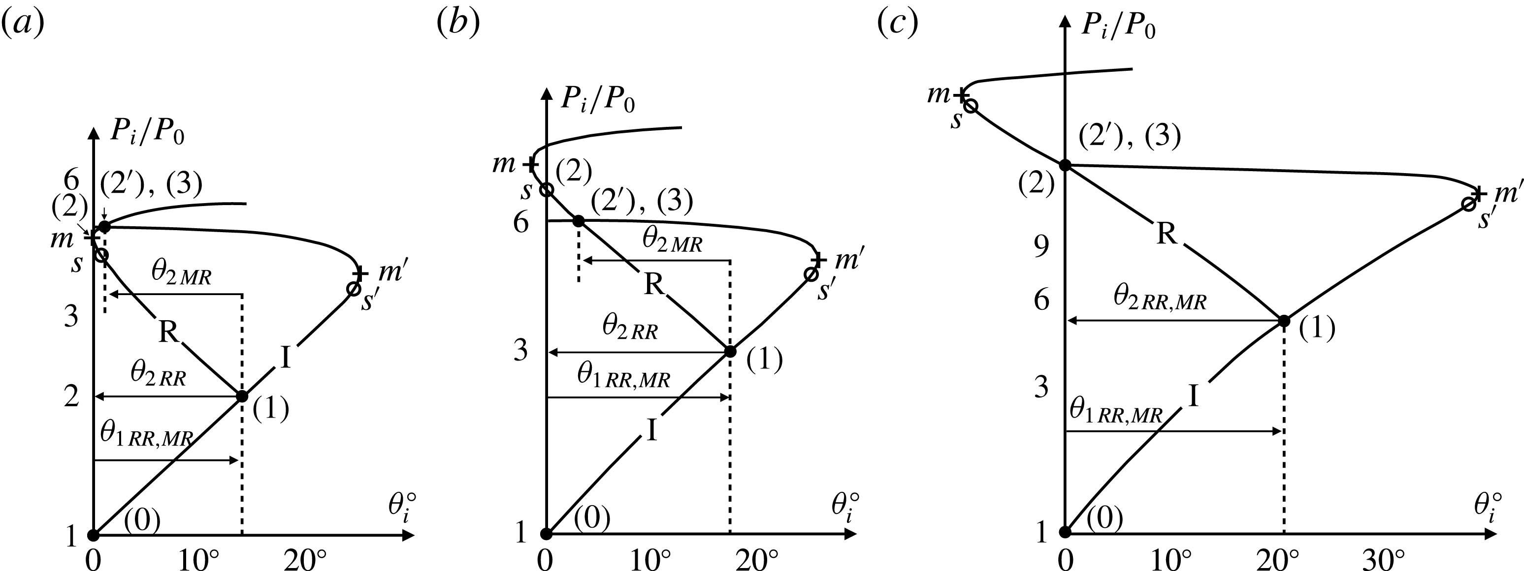
Figure 3. Shock polars demonstrating (a) the detachment criterion, (b) the sonic criterion and (c) the mechanical equilibrium criterion, adapted from Ben-Dor (Reference Ben-Dor2007).
The three accepted criteria for transition are the detachment criterion, the sonic criterion and the mechanical equilibrium (also known as the von Neumann) criterion. In all three plots, point
![]() $(2)$
resides on the
$(2)$
resides on the
![]() $P_{i}/P_{0}$
axis. In the case of the detachment criterion (figure 3
a), any further increase in the incident shock strength through an increase in
$P_{i}/P_{0}$
axis. In the case of the detachment criterion (figure 3
a), any further increase in the incident shock strength through an increase in
![]() $\unicode[STIX]{x1D703}$
will cause the
$\unicode[STIX]{x1D703}$
will cause the
![]() $R$
polar to move to the right and shrink, detaching point
$R$
polar to move to the right and shrink, detaching point
![]() $(2)$
from the
$(2)$
from the
![]() $P_{i}/P_{0}$
axis and jumping to the collocated
$P_{i}/P_{0}$
axis and jumping to the collocated
![]() $(2^{\prime }),(3)$
, and the shock reflection will transition from RR to MR. The sonic criterion is very similar to the detachment criterion, but with the detachment point being the sonic point
$(2^{\prime }),(3)$
, and the shock reflection will transition from RR to MR. The sonic criterion is very similar to the detachment criterion, but with the detachment point being the sonic point
![]() $s$
instead of point
$s$
instead of point
![]() $m$
. The sonic criterion contends that prior to reaching point
$m$
. The sonic criterion contends that prior to reaching point
![]() $s$
, any downstream effects (such as the presence of an expansion fan) cannot affect the reflection as information can only propagate downstream; however, after exceeding point
$s$
, any downstream effects (such as the presence of an expansion fan) cannot affect the reflection as information can only propagate downstream; however, after exceeding point
![]() $s$
, downstream information can propagate upstream to affect the reflection. Lock & Dewey (Reference Lock and Dewey1989) demonstrated the sonic criterion through experiment, proving its validity, but found that it is mainly applicable to pseudo-steady flows. The mechanical equilibrium criterion, originally suggested by von Neumann (Reference von Neumann1943a
,Reference von Neumann
b
) and studied in depth by Henderson & Lozzi (Reference Henderson and Lozzi1975), provides for a smooth transition from RR to MR in that a section of polar
$s$
, downstream information can propagate upstream to affect the reflection. Lock & Dewey (Reference Lock and Dewey1989) demonstrated the sonic criterion through experiment, proving its validity, but found that it is mainly applicable to pseudo-steady flows. The mechanical equilibrium criterion, originally suggested by von Neumann (Reference von Neumann1943a
,Reference von Neumann
b
) and studied in depth by Henderson & Lozzi (Reference Henderson and Lozzi1975), provides for a smooth transition from RR to MR in that a section of polar
![]() $R$
intersects the
$R$
intersects the
![]() $P_{i}/P_{0}$
axis at the same point as the strong section of the
$P_{i}/P_{0}$
axis at the same point as the strong section of the
![]() $I$
polar. This unique configuration of polars only exists for free-stream Mach numbers
$I$
polar. This unique configuration of polars only exists for free-stream Mach numbers
![]() $M_{0}\geqslant 2.2$
, above which transitional hysteresis can occur, finding all three criteria valid. However, for a steady flow with a free stream
$M_{0}\geqslant 2.2$
, above which transitional hysteresis can occur, finding all three criteria valid. However, for a steady flow with a free stream
![]() $1\leqslant M_{0}\leqslant 2.2$
, only the detachment criterion is valid.
$1\leqslant M_{0}\leqslant 2.2$
, only the detachment criterion is valid.
1.2 The SWBLI transition
Experimental investigation of transition criteria for inviscid shock reflections requires the removal of viscous effects such as the boundary layer at the reflecting surface. In practice, this is achieved through the creation of a symmetry plane in place of the wall, generated by an equal and opposite flow deflection with an equal and opposite oblique shock to generate an apparent RR or MR at the symmetry plane. However, the shock–shock interaction need not be perfectly symmetric, and transition can be observed with both symmetric and asymmetric interactions. In fact, Edney (Reference Edney1968) defined a classification system for such interactions, stating that there are six possible canonical shock–shock interaction types. Li, Chpoun & Ben-Dor (Reference Li, Chpoun and Ben-Dor1999) investigated the reflection of asymmetric shock waves in steady flows for
![]() $M_{0}=4.96$
, the results of which confirmed the detachment and mechanical equilibrium criteria as well as the dual solution domain which results in transitional hysteresis.
$M_{0}=4.96$
, the results of which confirmed the detachment and mechanical equilibrium criteria as well as the dual solution domain which results in transitional hysteresis.
In the asymmetric study of Li et al. (Reference Li, Chpoun and Ben-Dor1999), an opposing wedge is used to generate the opposing oblique shock. However, the use of a physical reflecting surface can also lead to an inviscid asymmetric shock–shock interaction, serving a similar purpose to the opposing wedge. An example of this can be seen in figure 4(a), which shows a schematic diagram of a strong separated SWBLI. In figure 4(a), the incident shock
![]() $C1$
is sufficiently strong to induce boundary layer separation between points
$C1$
is sufficiently strong to induce boundary layer separation between points
![]() $S$
and
$S$
and
![]() $R$
, and this separated region requires a flow deflection for the incoming supersonic flow, which gives rise to the separation shock
$R$
, and this separated region requires a flow deflection for the incoming supersonic flow, which gives rise to the separation shock
![]() $C2$
, resulting in an inviscid asymmetric shock–shock interaction at point
$C2$
, resulting in an inviscid asymmetric shock–shock interaction at point
![]() $T_{1}$
. In this way, the separation region/bubble acts in a similar way to the opposing wedge in the asymmetric study of Li et al. (Reference Li, Chpoun and Ben-Dor1999).
$T_{1}$
. In this way, the separation region/bubble acts in a similar way to the opposing wedge in the asymmetric study of Li et al. (Reference Li, Chpoun and Ben-Dor1999).
An accompanying example of an asymmetric shock polar for a strong SWBLI appears in figure 4(b). This shock polar, generated by an SWBLI, would be identical to an equivalent inviscid shock–shock interaction involving the same upstream flow conditions and flow deflection angles, analogous to those in the study of Li et al. (Reference Li, Chpoun and Ben-Dor1999), and thus it becomes clear that SWBLIs can approximate asymmetric shock–shock interactions.
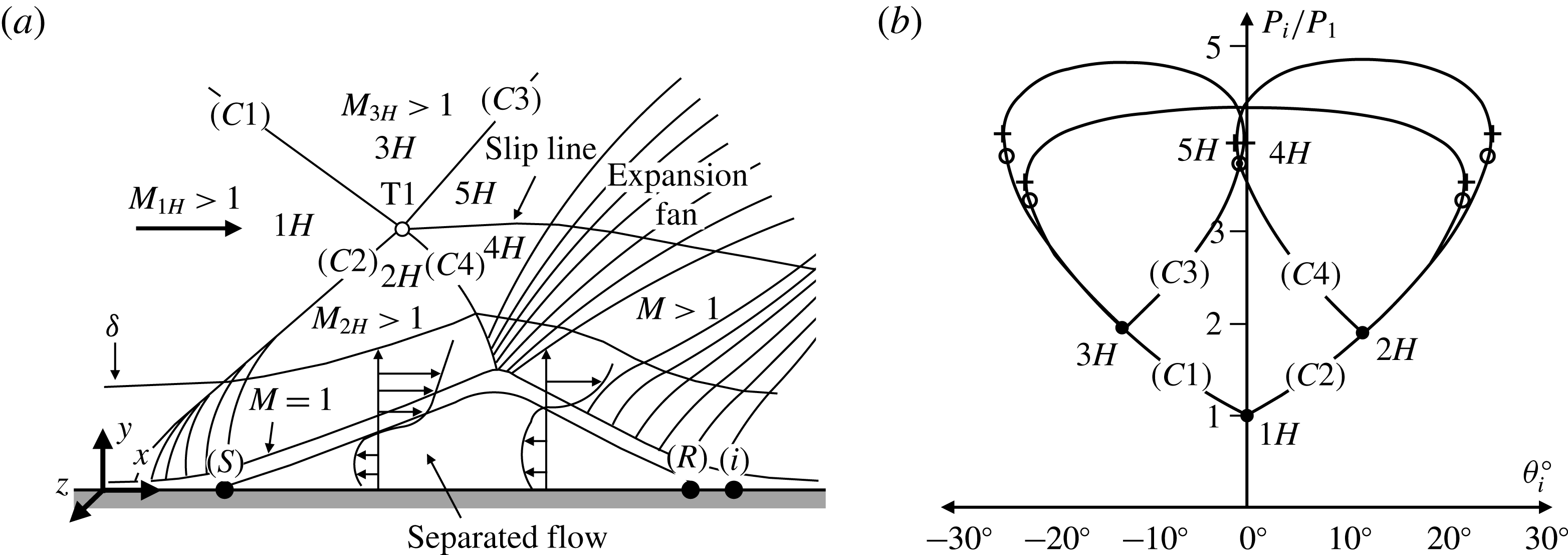
Figure 4. Moderate-strong SWBLI: (a) schematic diagram adapted and modified from Délery, Marvin & Reshotko (Reference Délery, Marvin and Reshotko1986); (b) shock polar.
Very little research into transition in SWBLIs exist, although recently Matheis & Hickel (Reference Matheis and Hickel2015) numerically investigated an
![]() $M_{0}=2$
incident–reflected SWBLI and transition between RR and MR. They performed three-dimensional large-eddy simulations (LES) without sidewalls with a spanwise domain of
$M_{0}=2$
incident–reflected SWBLI and transition between RR and MR. They performed three-dimensional large-eddy simulations (LES) without sidewalls with a spanwise domain of
![]() $L_{z}=4\unicode[STIX]{x1D6FF}_{ref}$
and a Reynolds number of
$L_{z}=4\unicode[STIX]{x1D6FF}_{ref}$
and a Reynolds number of
![]() $Re_{\unicode[STIX]{x1D6FF}}=4.8\times 10^{4}$
. They simulated a number of full-span shock generators with flow deflection angles of
$Re_{\unicode[STIX]{x1D6FF}}=4.8\times 10^{4}$
. They simulated a number of full-span shock generators with flow deflection angles of
![]() $\unicode[STIX]{x1D703}=11^{\circ }$
,
$\unicode[STIX]{x1D703}=11^{\circ }$
,
![]() $12^{\circ }$
,
$12^{\circ }$
,
![]() $12.5^{\circ }$
,
$12.5^{\circ }$
,
![]() $13^{\circ }$
and
$13^{\circ }$
and
![]() $14^{\circ }$
.
$14^{\circ }$
.
Matheis & Hickel (Reference Matheis and Hickel2015) found that transition occurred (in a time-averaged sense) at
![]() $\unicode[STIX]{x1D703}=14^{\circ }$
. They obtained mean values of the flow deflection behind the separation shock (e.g.
$\unicode[STIX]{x1D703}=14^{\circ }$
. They obtained mean values of the flow deflection behind the separation shock (e.g.
![]() $C2$
in figure 4
a) of
$C2$
in figure 4
a) of
![]() $\unicode[STIX]{x1D703}^{\prime }=10.53^{\circ }$
,
$\unicode[STIX]{x1D703}^{\prime }=10.53^{\circ }$
,
![]() $11.41^{\circ }$
,
$11.41^{\circ }$
,
![]() $11.41^{\circ }$
,
$11.41^{\circ }$
,
![]() $11.41^{\circ }$
and
$11.41^{\circ }$
and
![]() $11.50^{\circ }$
for the
$11.50^{\circ }$
for the
![]() $\unicode[STIX]{x1D703}=11^{\circ }$
,
$\unicode[STIX]{x1D703}=11^{\circ }$
,
![]() $12^{\circ }$
,
$12^{\circ }$
,
![]() $12.5^{\circ }$
,
$12.5^{\circ }$
,
![]() $13^{\circ }$
and
$13^{\circ }$
and
![]() $14^{\circ }$
cases respectively. Based upon the obtained
$14^{\circ }$
cases respectively. Based upon the obtained
![]() $\unicode[STIX]{x1D703}^{\prime }$
values, Matheis & Hickel (Reference Matheis and Hickel2015) concluded that the time-averaged separation shock angle remains nearly constant when the flow deflection is
$\unicode[STIX]{x1D703}^{\prime }$
values, Matheis & Hickel (Reference Matheis and Hickel2015) concluded that the time-averaged separation shock angle remains nearly constant when the flow deflection is
![]() $\unicode[STIX]{x1D703}>11^{\circ }$
. Matheis & Hickel (Reference Matheis and Hickel2015) also contended that this behaviour is characteristic of the free interaction theory of Chapman, Kuehn & Larson (Reference Chapman, Kuehn and Larson1958).
$\unicode[STIX]{x1D703}>11^{\circ }$
. Matheis & Hickel (Reference Matheis and Hickel2015) also contended that this behaviour is characteristic of the free interaction theory of Chapman, Kuehn & Larson (Reference Chapman, Kuehn and Larson1958).
Matheis & Hickel (Reference Matheis and Hickel2015) pointed out, assuming that the flow downstream of the separation shock remains constant at
![]() $\unicode[STIX]{x1D703}^{\prime }=11.41^{\circ }$
, that the detachment criterion would predict transition to occur for an incident shock flow deflection of
$\unicode[STIX]{x1D703}^{\prime }=11.41^{\circ }$
, that the detachment criterion would predict transition to occur for an incident shock flow deflection of
![]() $\unicode[STIX]{x1D703}\geqslant 14.21^{\circ }$
, which is higher than what they observed. At
$\unicode[STIX]{x1D703}\geqslant 14.21^{\circ }$
, which is higher than what they observed. At
![]() $\unicode[STIX]{x1D703}=11^{\circ }$
, they found the flow downstream of the SWBLI outside of the boundary layer to be fully supersonic. However, for
$\unicode[STIX]{x1D703}=11^{\circ }$
, they found the flow downstream of the SWBLI outside of the boundary layer to be fully supersonic. However, for
![]() $\unicode[STIX]{x1D703}\geqslant 12^{\circ }$
, they observed a small subsonic region immediately downstream of the SWBLI, centred around the shock interference triple point.
$\unicode[STIX]{x1D703}\geqslant 12^{\circ }$
, they observed a small subsonic region immediately downstream of the SWBLI, centred around the shock interference triple point.
Matheis & Hickel (Reference Matheis and Hickel2015) chose to investigate
![]() $\unicode[STIX]{x1D703}=13^{\circ }$
without time-averaging to investigate unsteadiness in the SWBLI. They found that the instantaneous flow deflection downstream of the separation shock fluctuated in the range
$\unicode[STIX]{x1D703}=13^{\circ }$
without time-averaging to investigate unsteadiness in the SWBLI. They found that the instantaneous flow deflection downstream of the separation shock fluctuated in the range
![]() $10.08^{\circ }<\unicode[STIX]{x1D703}<12.88^{\circ }$
and that the instantaneous flow deflection downstream of the incident shock fluctuated by of the order of
$10.08^{\circ }<\unicode[STIX]{x1D703}<12.88^{\circ }$
and that the instantaneous flow deflection downstream of the incident shock fluctuated by of the order of
![]() $\pm 0.25^{\circ }$
. They contended that this combined fluctuation of incident and separation shock angles resulted in occurrences where the required maximum flow deflections of the incident and separation shocks were instantaneously exceeded. In these instances, Mach reflections were observed and the height of the Mach stem varied in time with an apparent dependence upon the extent to which the maximum flow deflections had been exceeded.
$\pm 0.25^{\circ }$
. They contended that this combined fluctuation of incident and separation shock angles resulted in occurrences where the required maximum flow deflections of the incident and separation shocks were instantaneously exceeded. In these instances, Mach reflections were observed and the height of the Mach stem varied in time with an apparent dependence upon the extent to which the maximum flow deflections had been exceeded.
In general, such unsteadiness in shock-induced separation is a widely studied topic. It has been studied numerically by Touber & Sandham (Reference Touber and Sandham2008, Reference Touber and Sandham2009, Reference Touber and Sandham2011), Agostini, Larcheveque & Dupont (Reference Agostini, Larcheveque and Dupont2015) and experimentally/analytically by Ganapathisubramani, Clemens & Dolling (Reference Ganapathisubramani, Clemens and Dolling2009), Piponniau et al. (Reference Piponniau, Dussauge, Debieve and Dupont2009), Souverein, Bakker & Dupont (Reference Souverein, Bakker and Dupont2013), Rabey & Bruce (Reference Rabey and Bruce2017) and Threadgill & Bruce (Reference Threadgill and Bruce2017), to name just a few. However, the complete extent to which unsteadiness affects RR-SWBLI/MR-SWBLI transition, due to the limited number of studies regarding SWBLI transition, remains uncertain.
1.3 Motivation
As pointed out in the introduction, very little research into transition in SWBLIs exists. Matheis & Hickel (Reference Matheis and Hickel2015) investigated transition in SWBLI numerically, but to the best of the authors’ knowledge there exists no such experimental study on the topic. Furthermore, Matheis & Hickel (Reference Matheis and Hickel2015) chose not to include the effect of sidewalls; however, it is widely known that the inclusion of sidewalls can have a large effect on the resulting flow (Bruce et al. Reference Bruce, Burton, Titchener and Babinsky2011; Burton & Babinsky Reference Burton and Babinsky2012; Babinsky et al. Reference Babinsky, Oorebeek and Cottingham2013; Benek, Suchyta III & Babinsky Reference Benek, Suchyta and Babinsky2013; Galbraith et al. Reference Galbraith, Turner, Orkwisr and Weil2013; Wang et al. Reference Wang, Sandham, Hu and Liu2015). An experimental study would naturally include sidewall effects.
In addition to the above, in almost all experiments involving an oblique shock reflection, there exists a downstream expansion fan originating at the termination of the oblique shock generating wedge. Matheis & Hickel (Reference Matheis and Hickel2015) stated that, in general, this expansion fan has a large effect on the stability of the resulting SWBLI, claiming that there is a direct relationship between the SWBLI–expansion-fan separation and the adverse pressure gradient seen at the point of reattachment by the separated shear layer. This raises the question of the relationship the downstream expansion fan has with the upstream SWBLI.
Furthermore, in studying transition in inviscid asymmetric shock–shock interactions, it is common to leave one flow deflection fixed and increase the other. The study of Matheis & Hickel (Reference Matheis and Hickel2015) closely represents such an attempt, inducing transition through increase in the strength of the incident oblique shock while assuming that the separation shock strength remains nearly constant. It should be recalled that Matheis & Hickel (Reference Matheis and Hickel2015) observed this to be the case and concluded that this behaviour was characteristic of the free interaction theory of Chapman et al. (Reference Chapman, Kuehn and Larson1958). However, in light of their findings with respect to the triggering of transition, a question arises as to whether or not the time-averaged separation shock angle remains constant for all incident–reflected SWBLIs with separation and whether this is characteristic of free interaction theory.
Lastly, it should be mentioned that unsteadiness in shock-induced separation probably plays a large role in triggering transition between RR-SWBLI and MR-SWBLI, as Matheis & Hickel (Reference Matheis and Hickel2015) concluded. However, due to the low number of studies on the topic of SWBLI transition, basic questions remain regarding the general quasi-steady state arrangement and characteristics of SWBLI during transition.
In this study, we present the results from experiments with a novel set-up that allows us to
![]() $(1)$
experimentally observe transition of an incident–reflected SWBLI,
$(1)$
experimentally observe transition of an incident–reflected SWBLI,
![]() $(2)$
explore the relationship between the proximity of the downstream expansion fan and the SWBLI, and
$(2)$
explore the relationship between the proximity of the downstream expansion fan and the SWBLI, and
![]() $(3)$
investigate the applicability of free interaction theory in defining the mean separation shock angle. The experimental set-up, namely the wind tunnel facility, the traversable oblique shock generator and the experimental techniques used, are described in § 2. Results are presented and discussed in § 3, showing transition from RR to MR without an increase in incident shock strength as well as a relationship between separation bubble size, separation shock strength and expansion fan proximity. The key conclusions of the study are summarised in § 4 along with suggestions for future work.
$(3)$
investigate the applicability of free interaction theory in defining the mean separation shock angle. The experimental set-up, namely the wind tunnel facility, the traversable oblique shock generator and the experimental techniques used, are described in § 2. Results are presented and discussed in § 3, showing transition from RR to MR without an increase in incident shock strength as well as a relationship between separation bubble size, separation shock strength and expansion fan proximity. The key conclusions of the study are summarised in § 4 along with suggestions for future work.
2 Methodology
2.1 Wind tunnel
This investigation was conducted in the Imperial College London supersonic wind tunnel facility. A schematic diagram of the tunnel test section appears in figure 5. The Mach 2 blow-down wind tunnel is supplied with dried air stored in four
![]() $12~\text{m}^{3}$
tanks pressurised to 2.7 MPa and exhausts to atmosphere. The test section has dimensions of 150 mm wide
$12~\text{m}^{3}$
tanks pressurised to 2.7 MPa and exhausts to atmosphere. The test section has dimensions of 150 mm wide
![]() $\times$
150 mm tall
$\times$
150 mm tall
![]() $\times$
727 mm long and a unit Reynolds number of approximately
$\times$
727 mm long and a unit Reynolds number of approximately
![]() $2.0\times 10^{7}~\text{m}^{-1}$
. The desired flow conditions are achieved through the use of a PID controlled pneumatic pressure valve that maintains a commanded ratio of stagnation to atmospheric pressure (typically 1.8–2.9). Downstream of the control valve, turbulence levels are reduced by passing the flow through a settling chamber containing mesh screens and honeycomb prior to entering the nozzle and test section.
$2.0\times 10^{7}~\text{m}^{-1}$
. The desired flow conditions are achieved through the use of a PID controlled pneumatic pressure valve that maintains a commanded ratio of stagnation to atmospheric pressure (typically 1.8–2.9). Downstream of the control valve, turbulence levels are reduced by passing the flow through a settling chamber containing mesh screens and honeycomb prior to entering the nozzle and test section.
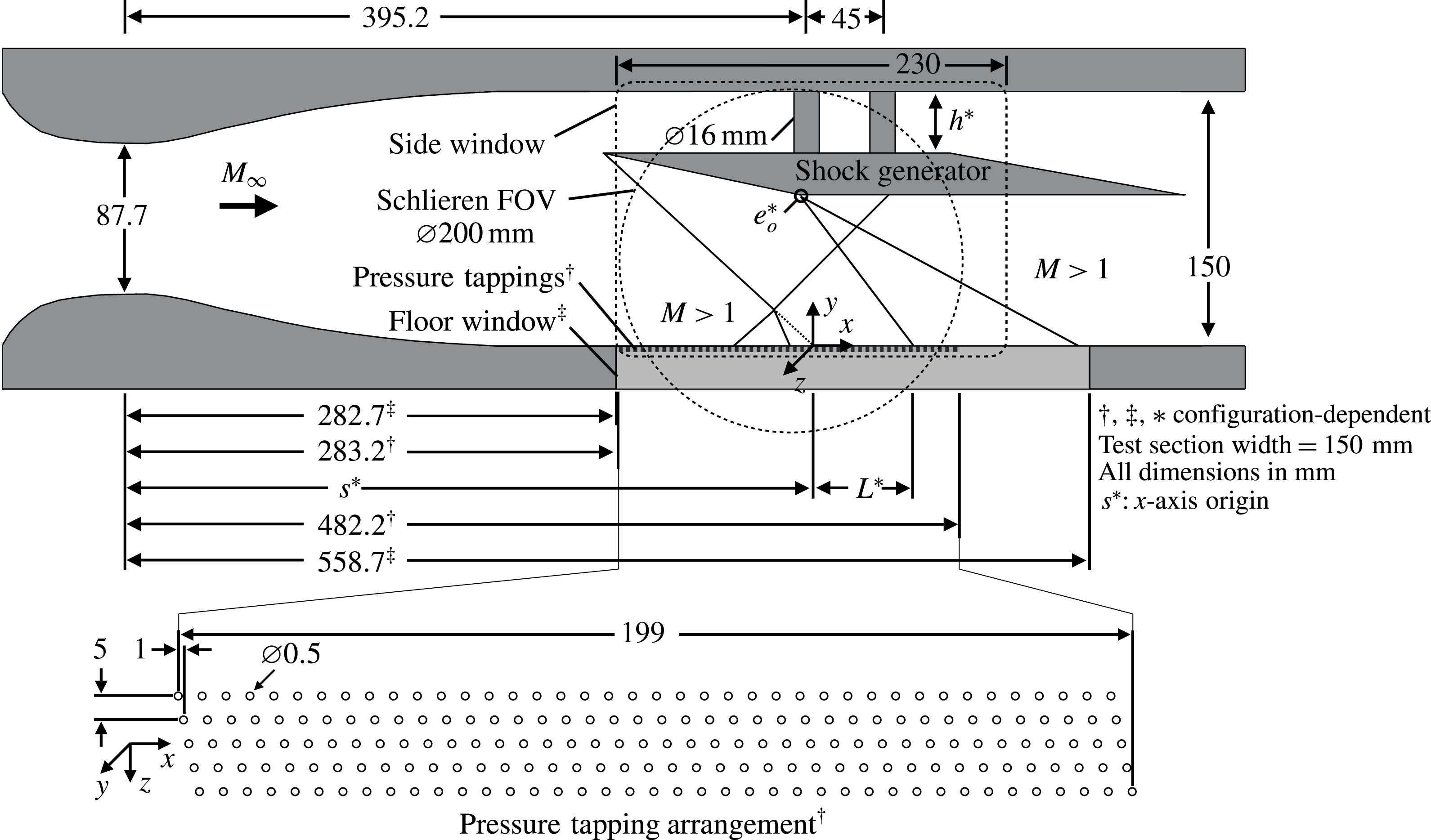
Figure 5. Schematic diagram of the wind tunnel set-up (see table 3 for the variable parameters
![]() $s$
,
$s$
,
![]() $h$
,
$h$
,
![]() $L$
and
$L$
and
![]() $e_{o}$
).
$e_{o}$
).
The test section boundary layer was characterised through the use of laser Doppler anemometry at a location immediately upstream of the SWBLI. The results are reported in table 1 for boundary layer thickness
![]() $(\unicode[STIX]{x1D6FF})$
, displacement thickness
$(\unicode[STIX]{x1D6FF})$
, displacement thickness
![]() $(\unicode[STIX]{x1D6FF}_{i}^{\ast })$
, momentum thickness
$(\unicode[STIX]{x1D6FF}_{i}^{\ast })$
, momentum thickness
![]() $(\unicode[STIX]{x1D703}_{i})$
, shape factor
$(\unicode[STIX]{x1D703}_{i})$
, shape factor
![]() $(H_{i})$
, Reynolds number
$(H_{i})$
, Reynolds number
![]() $(Re_{\unicode[STIX]{x1D703}_{i}})$
, coefficient of friction
$(Re_{\unicode[STIX]{x1D703}_{i}})$
, coefficient of friction
![]() $(C_{f})$
and friction velocity
$(C_{f})$
and friction velocity
![]() $(u_{\unicode[STIX]{x1D70F}})$
.
$(u_{\unicode[STIX]{x1D70F}})$
.
Table 1. Incompressible boundary layer profile parameters at streamwise locations (
![]() $x,z$
) based upon an
$x,z$
) based upon an
![]() $h=0$
,
$h=0$
,
![]() $12^{\circ }$
shock generator configuration. A dagger indicates a compressible value.
$12^{\circ }$
shock generator configuration. A dagger indicates a compressible value.
The general test configuration in figure 5 features a shock generator suspended at some distance from the wall (
![]() $h$
) which, during wind tunnel operation, generates an oblique shock wave originating from the tip. The shock wave impinges upon the wind tunnel floor boundary layer, resulting in an SWBLI. The inviscid impingement point at a distance
$h$
) which, during wind tunnel operation, generates an oblique shock wave originating from the tip. The shock wave impinges upon the wind tunnel floor boundary layer, resulting in an SWBLI. The inviscid impingement point at a distance
![]() $s$
from the nozzle throat marks the origin of the coordinate system for each test case. An expansion fan also originates from the corner (
$s$
from the nozzle throat marks the origin of the coordinate system for each test case. An expansion fan also originates from the corner (
![]() $e_{o}$
) on the underside of the shock generator. The relative arrangement of these features is dependent upon both the shock generator geometry and its deployed position
$e_{o}$
) on the underside of the shock generator. The relative arrangement of these features is dependent upon both the shock generator geometry and its deployed position
![]() $h$
, and is discussed in the following section. The
$h$
, and is discussed in the following section. The
![]() $z$
-axis origin is the test section centreline.
$z$
-axis origin is the test section centreline.
2.2 Shock generators
Four different oblique shock generator geometries were used. All were made of steel and took the form of three-dimensional parallelograms with a
![]() $12^{\circ }$
upstream facing wedge angle and
$12^{\circ }$
upstream facing wedge angle and
![]() $10^{\circ }$
downstream facing wedge angle. Care was taken to machine the wedge angles to a high tolerance, as confirmed by the accurate post-machining measurements listed in table 2. The shock generators were mounted to two struts which straddled the point of zero aerodynamic moment for each configuration. These struts protruded through access holes in the tunnel ceiling supported by two large linear bearings and attached to a traverse which allowed fine stream-normal adjustment of the tip of the shock generator in the
$10^{\circ }$
downstream facing wedge angle. Care was taken to machine the wedge angles to a high tolerance, as confirmed by the accurate post-machining measurements listed in table 2. The shock generators were mounted to two struts which straddled the point of zero aerodynamic moment for each configuration. These struts protruded through access holes in the tunnel ceiling supported by two large linear bearings and attached to a traverse which allowed fine stream-normal adjustment of the tip of the shock generator in the
![]() $y$
-axis of
$y$
-axis of
![]() $t<y<150$
mm (dependent upon shock generator thickness
$t<y<150$
mm (dependent upon shock generator thickness
![]() $t$
). The dimensions of the four shock generators are illustrated in figure 6. The shock generator label specifies the integer values for flow deflection angle in degrees plus any modifiers such as a rounded corner (e.g. SG12RC), and thickness in mm (e.g. T23).
$t$
). The dimensions of the four shock generators are illustrated in figure 6. The shock generator label specifies the integer values for flow deflection angle in degrees plus any modifiers such as a rounded corner (e.g. SG12RC), and thickness in mm (e.g. T23).
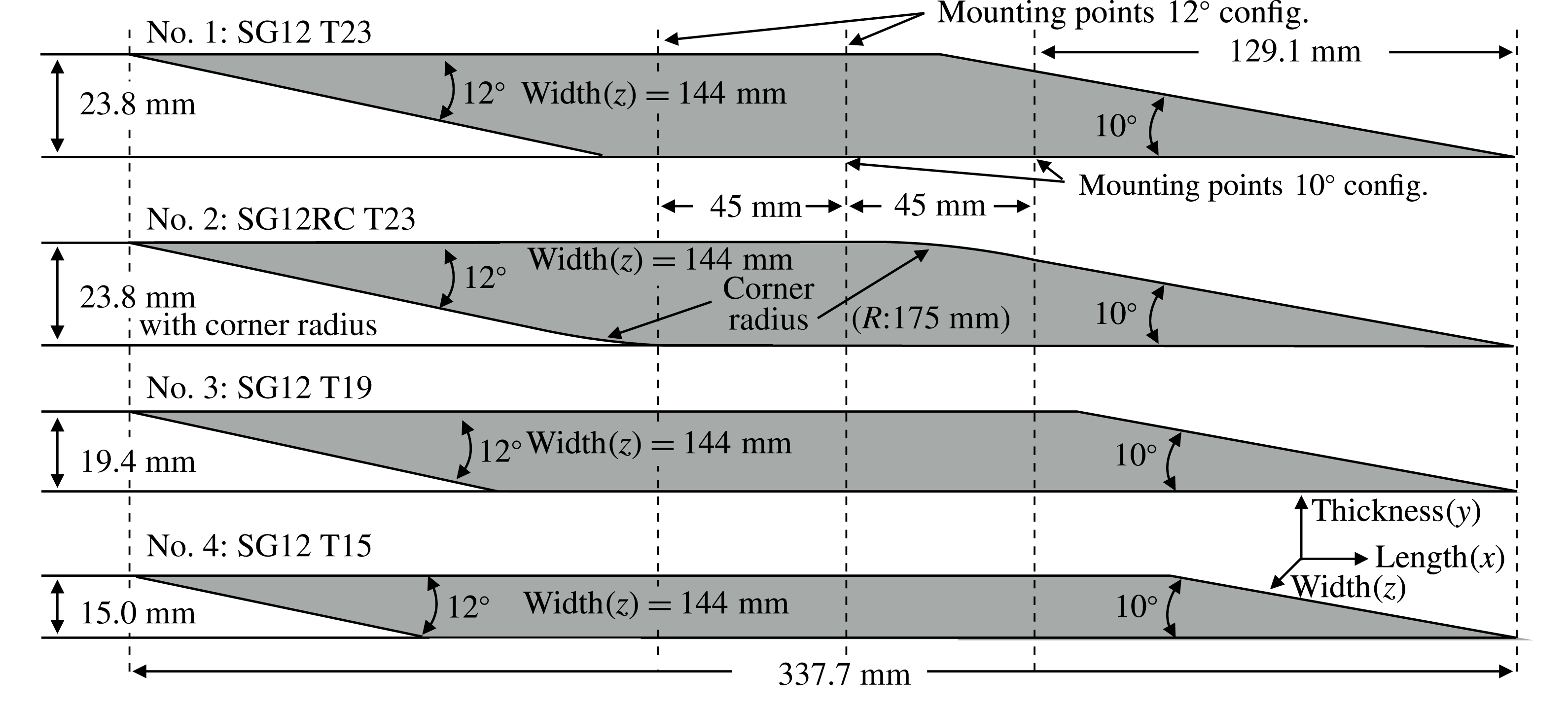
Figure 6. Shock generator schematic diagrams.
Table 2. Nominal and measured test article upstream (U) and downstream (D) facing wedge angles.

All of the shock generators were 337.7 mm long and 144 mm wide (96 % span) giving 3 mm sidewall gaps to allow vertical traversing during wind tunnel operation. They were all identical except for the thickness (
![]() $t$
) of the shock generator (
$t$
) of the shock generator (
![]() $T$
), which for nos.
$T$
), which for nos.
![]() $1$
,
$1$
,
![]() $3$
and
$3$
and
![]() $4$
was set to 23.8 mm, 19.4 mm and 15.0 mm respectively. Shock generator no.
$4$
was set to 23.8 mm, 19.4 mm and 15.0 mm respectively. Shock generator no.
![]() $2$
was identical to no.
$2$
was identical to no.
![]() $1$
except for a 175 mm radius cut into the expansion fan sharp corner. By varying the thickness of the shock generator, the placement of the expansion fan origin
$1$
except for a 175 mm radius cut into the expansion fan sharp corner. By varying the thickness of the shock generator, the placement of the expansion fan origin
![]() $e_{o}$
is physically shifted. By putting a radius on the expansion fan corner,
$e_{o}$
is physically shifted. By putting a radius on the expansion fan corner,
![]() $e_{o}$
is virtually shifted upstream and stream-normal relative to the non-radius case of the same thickness, with the virtual
$e_{o}$
is virtually shifted upstream and stream-normal relative to the non-radius case of the same thickness, with the virtual
![]() $e_{o}$
being defined as the origin of a virtual expansion fan possessing the same first and last expansion fan characteristic impingement points as the actual expansion fan resulting from a rounded corner.
$e_{o}$
being defined as the origin of a virtual expansion fan possessing the same first and last expansion fan characteristic impingement points as the actual expansion fan resulting from a rounded corner.
Use of a traverse to adjust stream-normal placement (
![]() $h$
) of the upstream leading edge of the shock generator allows an effective change in the wind tunnel aspect ratio and confinement. We define this effective change in aspect ratio
$h$
) of the upstream leading edge of the shock generator allows an effective change in the wind tunnel aspect ratio and confinement. We define this effective change in aspect ratio
![]() $(AR_{eff})$
as the test section width divided by the height of the shock generator upstream leading edge. This yields a trend of an increase in
$(AR_{eff})$
as the test section width divided by the height of the shock generator upstream leading edge. This yields a trend of an increase in
![]() $AR_{eff}$
and a greater confinement or area reduction as the shock generator is lowered. An
$AR_{eff}$
and a greater confinement or area reduction as the shock generator is lowered. An
![]() $AR_{eff}$
range of 1.00–1.38 was found to be achievable for all configurations. A change in
$AR_{eff}$
range of 1.00–1.38 was found to be achievable for all configurations. A change in
![]() $AR_{eff}$
also has an effect on the placement of
$AR_{eff}$
also has an effect on the placement of
![]() $e_{o}$
(
$e_{o}$
(
![]() $x_{e_{o}},y_{e_{o}}$
) relative to the inviscid incident oblique shock impingement point. This results in various distances
$x_{e_{o}},y_{e_{o}}$
) relative to the inviscid incident oblique shock impingement point. This results in various distances
![]() $L$
(see figure 5) between the inviscid incident oblique shock impingement and expansion fan impingement. These values are listed in table 3 and represent all of the test cases considered.
$L$
(see figure 5) between the inviscid incident oblique shock impingement and expansion fan impingement. These values are listed in table 3 and represent all of the test cases considered.
Table 3. Key dimensions of expansion fan origin placement and separation for all configurations tested (reference figure 5).

2.3 Experimental techniques
The flow fields produced in this study were observed utilising a combination of measurement techniques including Schlieren photography, particle image velocimetry (PIV), surface oil flow visualisation and high-spatial-resolution static pressure tappings.
Schlieren photography allowed the visualisation of detailed SWBLI shock structures as well as larger field of view items such as the incident oblique shock, reflected shock and expansion fan. A ‘Z’ configuration was used consisting of an LED point light source with 1 mm pin hole filter projecting onto a 200 mm diameter hemispheric mirror with a 1200 mm focal length. A second hemispherical mirror focused the light down to a conventional vertical oriented ‘knife-edge’ and was passed through a
![]() $105$
mm lens (Sigma EX DG Macro) with an
$105$
mm lens (Sigma EX DG Macro) with an
![]() $f$
-stop of
$f$
-stop of
![]() $2.8$
. The resulting image was recorded with a high-speed camera (Phantom v641). The high-speed camera recorded
$2.8$
. The resulting image was recorded with a high-speed camera (Phantom v641). The high-speed camera recorded
![]() $300$
frames a second at a resolution of
$300$
frames a second at a resolution of
![]() $2048\times 1536$
(
$2048\times 1536$
(
![]() ${\approx}8.6~\text{pix}~\text{mm}^{-1}$
) with an exposure of
${\approx}8.6~\text{pix}~\text{mm}^{-1}$
) with an exposure of
![]() $30~\unicode[STIX]{x03BC}\text{s}$
.
$30~\unicode[STIX]{x03BC}\text{s}$
.
Planar vector fields were obtained through the use of PIV. Illumination was provided by a Nd:YLF class IV laser outputting
![]() $30~\text{mJ}~\text{pulse}^{-1}$
at a wavelength of 527 nm. The laser beam was formed into a 2 mm thick sheet with beam to sheet forming optics. Di-ethyl-hexyl-sebacat droplets, of approximately 0.3
$30~\text{mJ}~\text{pulse}^{-1}$
at a wavelength of 527 nm. The laser beam was formed into a 2 mm thick sheet with beam to sheet forming optics. Di-ethyl-hexyl-sebacat droplets, of approximately 0.3
![]() $\unicode[STIX]{x03BC}\text{m}$
mean diameter, were injected into the settling chamber of the tunnel ahead of the flow conditioning screens from six radially spaced probes connected to an aerosol pumping system (PivTec). For each configuration, 2732 image pairs were captured from a single high-speed camera (Phantom v641), at 720 Hz, attached to a telecentric lens (Opto Engineering TC16M-144) at a distance of approximately 400 mm from the interaction. The exact parameters used in this investigation can be found in table 4. Unlike the schlieren photography, the PIV results were obtained in individual runs of the wind tunnel due to data acquisition limitations, and therefore a small velocity correction (relative to the first experiment) was necessary to account for slight variations in temperature between runs.
$\unicode[STIX]{x03BC}\text{m}$
mean diameter, were injected into the settling chamber of the tunnel ahead of the flow conditioning screens from six radially spaced probes connected to an aerosol pumping system (PivTec). For each configuration, 2732 image pairs were captured from a single high-speed camera (Phantom v641), at 720 Hz, attached to a telecentric lens (Opto Engineering TC16M-144) at a distance of approximately 400 mm from the interaction. The exact parameters used in this investigation can be found in table 4. Unlike the schlieren photography, the PIV results were obtained in individual runs of the wind tunnel due to data acquisition limitations, and therefore a small velocity correction (relative to the first experiment) was necessary to account for slight variations in temperature between runs.
Table 4. The PIV measurement parameters.
![]() $^{\ast }$
Note: telecentric lenses have no practical focal length or
$^{\ast }$
Note: telecentric lenses have no practical focal length or
![]() $f$
-stop.
$f$
-stop.
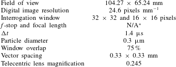
Surface oil flow visualisation was achieved by injecting a high-contrast oil mixture over a matte black floor plate just upstream of each SWBLI. The mixture consisted of titanium dioxide, oleic acid and kerosene, and was filmed through a sidewall window using a camera (Nikon D7000 DSLR) in video mode. Schematics of the imaged surface oil flow topologies were generated by tracing over the streamlines present in the images. All images presented in this study were imaged in situ during the experiment to avoid any wind tunnel shut down transient and/or erroneous features that could be imprinted after the fact. During each wind tunnel experiment, a still frame was selected from the video and dewarped with the aid of a calibration target (imaged before each experiment) to correct for camera perspective and to provide physical scale.
Streamwise high-spatial-resolution (1 mm) static pressure measurements were obtained through the resulting SWBLIs. Geometrical constraints precluded the static pressure tappings from being aligned perfectly on the centreline. Instead, 1 mm streamwise precision was achieved with a staggered array of 200 static pressure ports, the arrangement of which is illustrated in figure 5. Two 16-channel pressure transducer arrays (Pressure Systems 9116 Netscanner) were used. Collection of data across the 199 mm range required the wind tunnel to be repeatedly run for an identical configuration, disconnecting previously measured static tappings and reconnecting new static tappings (all disconnected tubes were fitted with plugs to ensure no leakage of flow from outside the test section). The pressure transducers were recalibrated before every measurement to null offset drift errors, as well as wind tunnel runs being performed in quick succession to avoid any drift due to changes in the atmospheric conditions. The use of this procedure resulted in composite pressure profiles that fell well within the measurement accuracy of the pressure transducers (
![]() $\pm 0.0135$
psia).
$\pm 0.0135$
psia).
3 Results
3.1 Regular–irregular transition
In this section, results obtained with the no. 1: SG12T23 shock generator at
![]() $AR_{eff}$
in the range
$AR_{eff}$
in the range
![]() $1$
–
$1$
–
![]() $1.38$
are presented. The evolution of the SWBLI structure is shown through schlieren photography.
$1.38$
are presented. The evolution of the SWBLI structure is shown through schlieren photography.
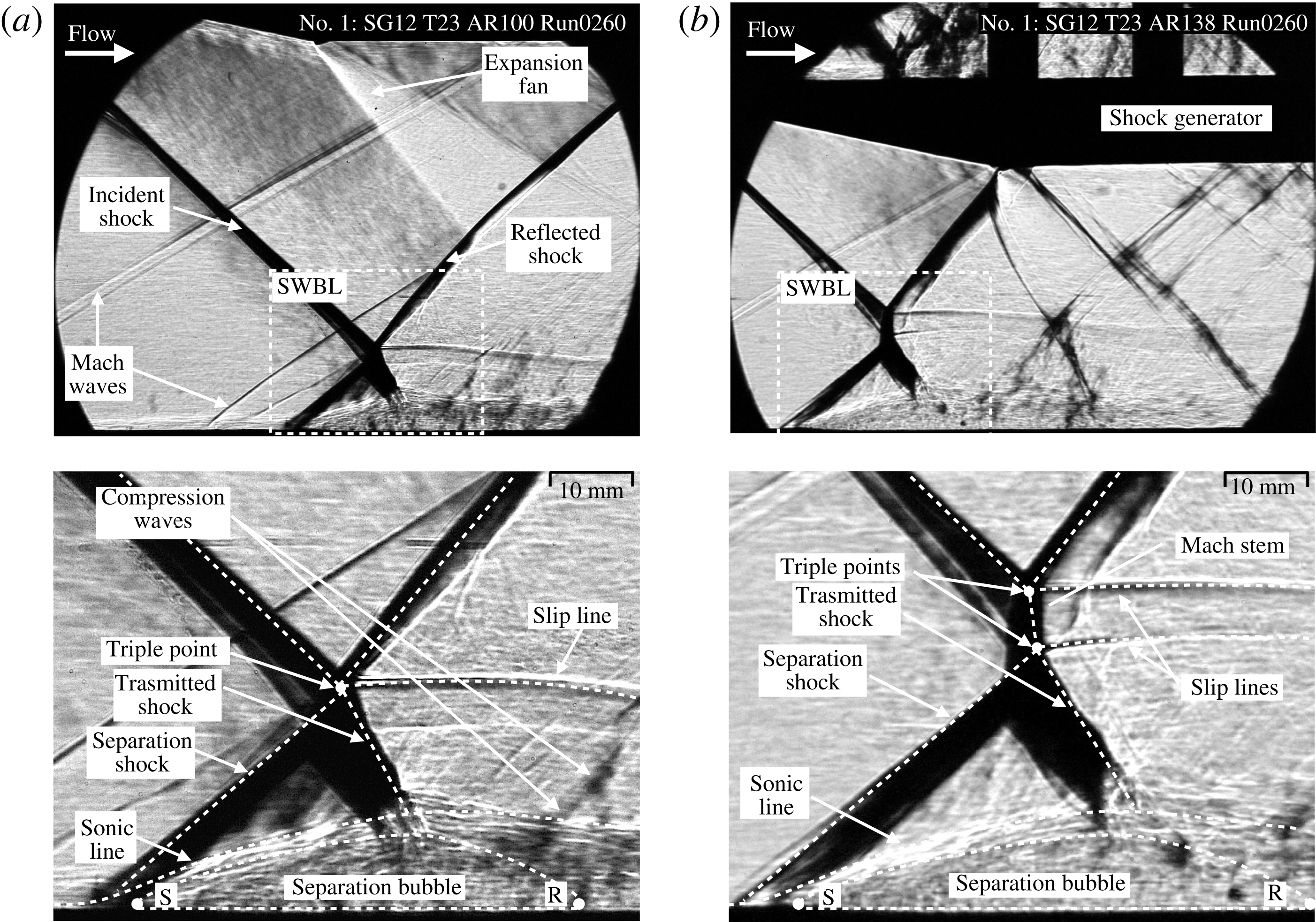
Figure 7. Schlieren photography of no. 1: SG12T23 SWBLI showing the effect of
![]() $AR_{eff}=1.00$
–
$AR_{eff}=1.00$
–
![]() $1.38$
(
$1.38$
(
![]() $M_{0}=2$
,
$M_{0}=2$
,
![]() $\unicode[STIX]{x1D703}=12^{\circ }$
): (a)
$\unicode[STIX]{x1D703}=12^{\circ }$
): (a)
![]() $AR_{eff}=1.00$
; (b)
$AR_{eff}=1.00$
; (b)
![]() $AR_{eff}=1.38$
.
$AR_{eff}=1.38$
.
The
![]() $\unicode[STIX]{x1D703}=12^{\circ }$
flow deflection yields a strong SWBLI which results in both a large well-defined SWBLI structure and a large region of shock-induced boundary layer separation. Figure 7 shows the large-scale field of view of the interactions along with detailed views for the
$\unicode[STIX]{x1D703}=12^{\circ }$
flow deflection yields a strong SWBLI which results in both a large well-defined SWBLI structure and a large region of shock-induced boundary layer separation. Figure 7 shows the large-scale field of view of the interactions along with detailed views for the
![]() $AR_{eff}=1.00$
and
$AR_{eff}=1.00$
and
![]() $AR_{eff}=1.38$
cases. The images in figure 7 were all taken from a single wind tunnel run separated by approximately 15 s with all conditions held constant except
$AR_{eff}=1.38$
cases. The images in figure 7 were all taken from a single wind tunnel run separated by approximately 15 s with all conditions held constant except
![]() $AR_{eff}$
. In the images, several features can be seen: the shock generator, the incident shock, the reflected shock, an expansion fan, the SWBLIs themselves and a few Mach waves originating from wall joints or imperfectly cancelled waves from the nozzle expansion which are so weak that they do not influence the flow. In both cases, the adverse pressure gradient imposed by the incident oblique shock causes the boundary layer to separate. The approximate extent of flow separation is marked by
$AR_{eff}$
. In the images, several features can be seen: the shock generator, the incident shock, the reflected shock, an expansion fan, the SWBLIs themselves and a few Mach waves originating from wall joints or imperfectly cancelled waves from the nozzle expansion which are so weak that they do not influence the flow. In both cases, the adverse pressure gradient imposed by the incident oblique shock causes the boundary layer to separate. The approximate extent of flow separation is marked by
![]() $S$
and
$S$
and
![]() $R$
and enclosed by a dotted line in both figures, as indicated by the separation shock and compression waves respectively. The flow is deflected up away from the wall and over the separation bubble by the separation shock, before being turned back down as it travels through the transmitted shock. The separation shock travels up and interacts with the original incident shock. The SWBLI seen in figure 7(a), using the classification system of Edney (Reference Edney1968) mentioned in the introduction, would be regarded as a type I interference, which corresponds to an RR-SWBLI. In the figure, from the point of interference or triple point, two other shocks emanate away. One is the reflection from the incident shock (travelling away from the floor) and the other is commonly referred to as the ‘transmitted’ shock (travelling towards the floor). These two shocks turn the two flows above and below the triple point back parallel to each other. Also originating at the triple point and travelling downstream is a slip line. The presence of a slip line is indicative of an entropy mismatch between the paths above and below the triple point as they encounter shocks of different strengths. Downstream of the SWBLI, the expansion fan impinges upon the floor. The role of the expansion fan in affecting the SWBLI will be discussed later in § 3.4.
$R$
and enclosed by a dotted line in both figures, as indicated by the separation shock and compression waves respectively. The flow is deflected up away from the wall and over the separation bubble by the separation shock, before being turned back down as it travels through the transmitted shock. The separation shock travels up and interacts with the original incident shock. The SWBLI seen in figure 7(a), using the classification system of Edney (Reference Edney1968) mentioned in the introduction, would be regarded as a type I interference, which corresponds to an RR-SWBLI. In the figure, from the point of interference or triple point, two other shocks emanate away. One is the reflection from the incident shock (travelling away from the floor) and the other is commonly referred to as the ‘transmitted’ shock (travelling towards the floor). These two shocks turn the two flows above and below the triple point back parallel to each other. Also originating at the triple point and travelling downstream is a slip line. The presence of a slip line is indicative of an entropy mismatch between the paths above and below the triple point as they encounter shocks of different strengths. Downstream of the SWBLI, the expansion fan impinges upon the floor. The role of the expansion fan in affecting the SWBLI will be discussed later in § 3.4.

Figure 8. The SWBLI structure evolution for no. 1: SG12T23,
![]() $AR_{eff}=1.00$
–
$AR_{eff}=1.00$
–
![]() $1.38$
.
$1.38$
.
Figure 7(a) shows a broadly similar SWBLI structure to that in figure 7(b). However, in 7(b), the SWBLI features two slip lines and two triple points, with a near-normal shock region joining the triple points together. This structure is classified by Edney (Reference Edney1968) as a type II interference, corresponding to a Mach reflection (MR) SWBLI. At this higher
![]() $AR_{eff}$
, the separation bubble is larger (as indicated by larger streamwise displacement of the separation and transmitted shock), and the presence of an MR-SWBLI suggests that the flow must be turned by a greater amount. As the flow is deflected up away from the wall and over the separation bubble, it must again be turned back down as it travels through the transmitted shock. The presence of a type II interference suggests that the flow turning angle required to turn the flow parallel to the incoming flow as it passes through the transmitted shock is in excess of the maximum turning angle for the flow
$AR_{eff}$
, the separation bubble is larger (as indicated by larger streamwise displacement of the separation and transmitted shock), and the presence of an MR-SWBLI suggests that the flow must be turned by a greater amount. As the flow is deflected up away from the wall and over the separation bubble, it must again be turned back down as it travels through the transmitted shock. The presence of a type II interference suggests that the flow turning angle required to turn the flow parallel to the incoming flow as it passes through the transmitted shock is in excess of the maximum turning angle for the flow
![]() $(\unicode[STIX]{x1D703}_{max})$
as defined by the solution to the Rankine–Hugoniot equations (
$(\unicode[STIX]{x1D703}_{max})$
as defined by the solution to the Rankine–Hugoniot equations (
![]() $\unicode[STIX]{x1D703}$
–
$\unicode[STIX]{x1D703}$
–
![]() $\unicode[STIX]{x1D6FD}$
–
$\unicode[STIX]{x1D6FD}$
–
![]() $M$
relationship). In this situation, the flows above and below the triple points can no longer be turned parallel to each other. This is evident in the way that the slip lines are very slightly angled towards each other with a narrowing distance between them as they flow downstream. In order to satisfy these flow conditions, a near-normal shock or Mach stem forms between the two triple points, with the region immediately behind the Mach stem being subsonic. Further downstream, the narrowing of slip lines causes reacceleration of the post-shock flow, eventually returning to supersonic speeds. The evolution of the SWBLI with changing
$M$
relationship). In this situation, the flows above and below the triple points can no longer be turned parallel to each other. This is evident in the way that the slip lines are very slightly angled towards each other with a narrowing distance between them as they flow downstream. In order to satisfy these flow conditions, a near-normal shock or Mach stem forms between the two triple points, with the region immediately behind the Mach stem being subsonic. Further downstream, the narrowing of slip lines causes reacceleration of the post-shock flow, eventually returning to supersonic speeds. The evolution of the SWBLI with changing
![]() $AR_{eff}$
is studied in more detail in figure 8, which shows the gradual transition of the SWBLI from RR to MR at intermediate values of
$AR_{eff}$
is studied in more detail in figure 8, which shows the gradual transition of the SWBLI from RR to MR at intermediate values of
![]() $AR_{eff}$
. In the figure, the SWBLI size is seen to increase with an increase in
$AR_{eff}$
. In the figure, the SWBLI size is seen to increase with an increase in
![]() $AR_{eff}$
. Here, we define SWBLI size as the height of the triple point(s) above the wind tunnel floor.
$AR_{eff}$
. Here, we define SWBLI size as the height of the triple point(s) above the wind tunnel floor.
3.2 Change in boundary layer parameters with effective aspect ratio
Specific to the arrangement used in the current study, boundary layer parameters do vary slightly for SWBLIs at different values of
![]() $AR_{eff}$
due to the fact that as
$AR_{eff}$
due to the fact that as
![]() $AR_{eff}$
is increased, the shock impingement point moves upstream relative to the shock generator and therefore experiences a boundary layer at a different stage of development. This movement spans
$AR_{eff}$
is increased, the shock impingement point moves upstream relative to the shock generator and therefore experiences a boundary layer at a different stage of development. This movement spans
![]() $\unicode[STIX]{x0394}x\approx 46$
mm (
$\unicode[STIX]{x0394}x\approx 46$
mm (
![]() ${\approx}8.6\unicode[STIX]{x1D6FF}$
) for
${\approx}8.6\unicode[STIX]{x1D6FF}$
) for
![]() $AR_{eff}=1.00$
–
$AR_{eff}=1.00$
–
![]() $1.38$
. In the previous section, it was seen that an increase in
$1.38$
. In the previous section, it was seen that an increase in
![]() $AR_{eff}$
is accompanied by an increase in SWBLI size and strength. Since the boundary layer parameters are different for each case presented in figures 7 and 8, the question of boundary layer influence on the observations needs to be addressed.
$AR_{eff}$
is accompanied by an increase in SWBLI size and strength. Since the boundary layer parameters are different for each case presented in figures 7 and 8, the question of boundary layer influence on the observations needs to be addressed.
A study by Threadgill & Bruce (Reference Threadgill and Bruce2016) was performed in the same wind tunnel at the same free-stream conditions. In the study, the evolution of the boundary layer profile was characterised from
![]() ${\approx}95$
to
${\approx}95$
to
![]() $45$
mm upstream of the
$45$
mm upstream of the
![]() $AR_{eff}=1.00$
inviscid shock impingement point. Across this distance,
$AR_{eff}=1.00$
inviscid shock impingement point. Across this distance,
![]() $\unicode[STIX]{x1D6FF}$
grew by
$\unicode[STIX]{x1D6FF}$
grew by
![]() ${\approx}0.2\,\%$
/mm. However, the shape factor (a parameter that has a large effect on SWBLI structure) remained nearly constant. Furthermore, not only is the expected change in boundary layer thickness over this distance small, but the trend is such that as
${\approx}0.2\,\%$
/mm. However, the shape factor (a parameter that has a large effect on SWBLI structure) remained nearly constant. Furthermore, not only is the expected change in boundary layer thickness over this distance small, but the trend is such that as
![]() $AR_{eff}$
is increased, the SWBLI will experience a smaller boundary layer thicknesses. With this trend, one might expect to see a trend of smaller SWBLIs at higher values of
$AR_{eff}$
is increased, the SWBLI will experience a smaller boundary layer thicknesses. With this trend, one might expect to see a trend of smaller SWBLIs at higher values of
![]() $AR_{eff}$
. However, as shown in figures 7 and 8, the effect of
$AR_{eff}$
. However, as shown in figures 7 and 8, the effect of
![]() $AR_{eff}$
is so strong that it overcomes this boundary layer effect and the growth of SWBLIs at higher values of
$AR_{eff}$
is so strong that it overcomes this boundary layer effect and the growth of SWBLIs at higher values of
![]() $AR_{eff}$
is observed.
$AR_{eff}$
is observed.
3.3 Average centreline velocity field and separation topology
Although the images in figures 7 and 8 are representative of the flow field for each test case, some unsteadiness of the flow was observed and hence frame-to-frame variations. Therefore, in order to infer the shock angles, particularly for the separation shock, mean velocity field measurements (averaged over
![]() $3.8$
s) were obtained with PIV. In figure 9, the PIV velocity fields around the
$3.8$
s) were obtained with PIV. In figure 9, the PIV velocity fields around the
![]() $\unicode[STIX]{x1D703}=12^{\circ }$
SWBLI are presented. Figure 9(a,c,e) shows the SWBLI when
$\unicode[STIX]{x1D703}=12^{\circ }$
SWBLI are presented. Figure 9(a,c,e) shows the SWBLI when
![]() $AR_{eff}$
is set to
$AR_{eff}$
is set to
![]() $1.00$
and figure 9(b,d,f) shows the SWBLI when
$1.00$
and figure 9(b,d,f) shows the SWBLI when
![]() $AR_{eff}$
is set to
$AR_{eff}$
is set to
![]() $1.38$
.
$1.38$
.
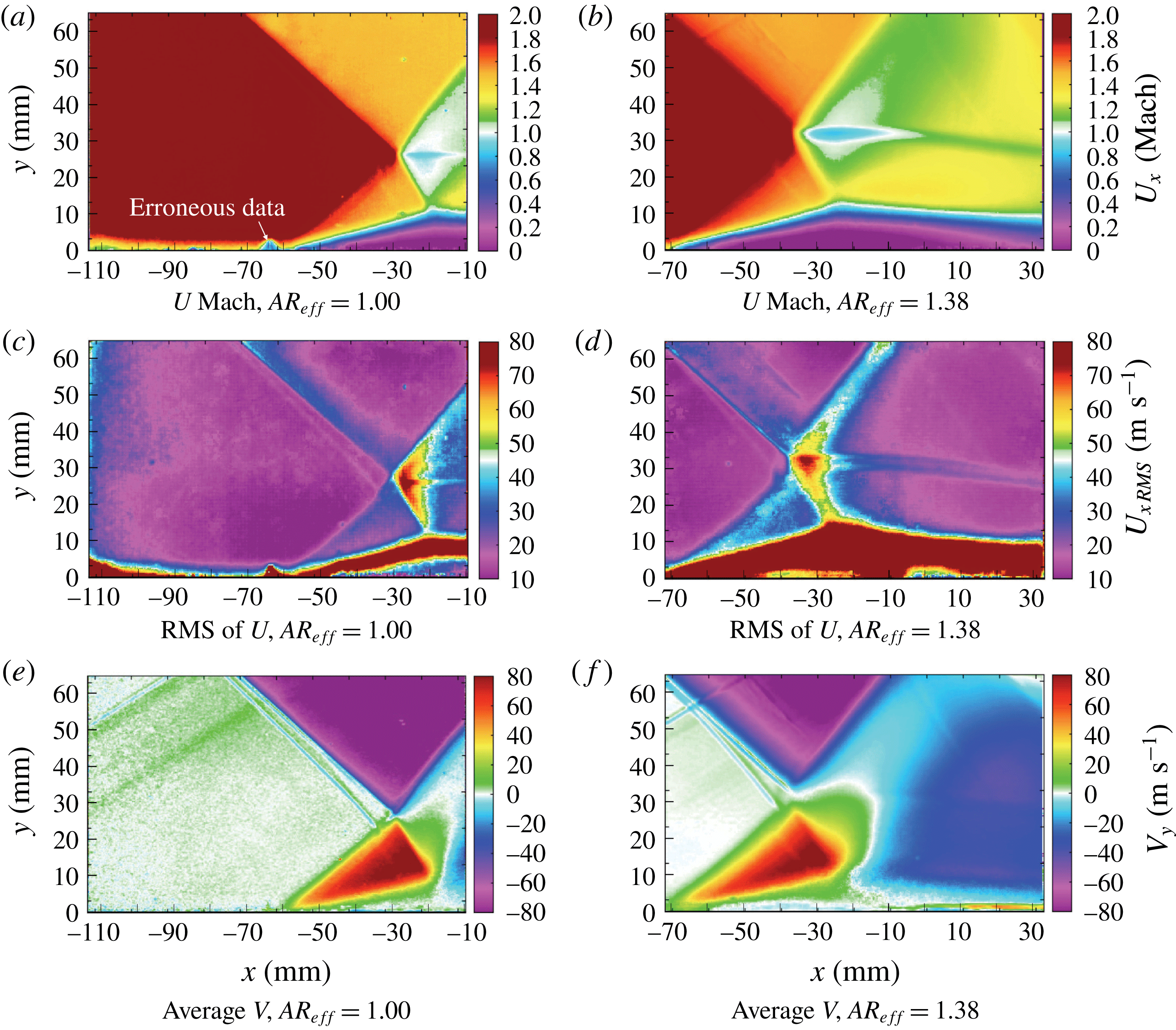
Figure 9. The PIV velocity field measurements for no. 1: SG12T23 SWBLI,
![]() $AR_{eff}=1.00$
–
$AR_{eff}=1.00$
–
![]() $1.38$
(
$1.38$
(
![]() $M_{0}=2$
,
$M_{0}=2$
,
![]() $\unicode[STIX]{x1D703}=12^{\circ }$
).
$\unicode[STIX]{x1D703}=12^{\circ }$
).
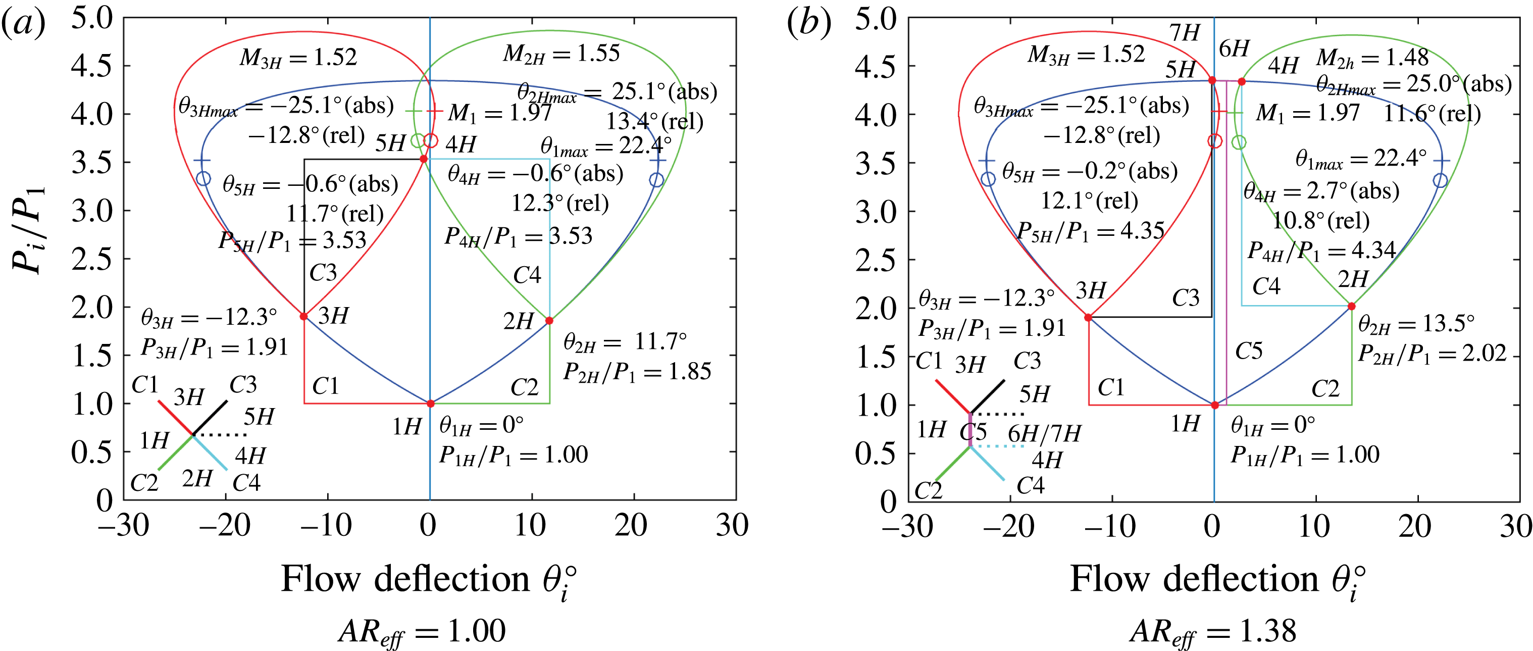
Figure 10. Effect of
![]() $AR_{eff}$
on shock polar plots for SWBLIs with
$AR_{eff}$
on shock polar plots for SWBLIs with
![]() $\unicode[STIX]{x1D703}=12^{\circ }$
.
$\unicode[STIX]{x1D703}=12^{\circ }$
.
When the
![]() $AR_{eff}$
is increased from
$AR_{eff}$
is increased from
![]() $1.00$
to
$1.00$
to
![]() $1.38$
, the evolution from RR-SWBLI (figure 9
a) into MR-SWBLI (figure 9
b) can again be observed. In figure 9(b), the region at approximately
$1.38$
, the evolution from RR-SWBLI (figure 9
a) into MR-SWBLI (figure 9
b) can again be observed. In figure 9(b), the region at approximately
![]() $x\approx -25$
mm,
$x\approx -25$
mm,
![]() $y\approx 30$
mm qualitatively grows in size and the formation of the Mach stem is seen as the interaction/triple point between the incident and reflected shocks moves up away from the interaction/triple point of the separation and transmitted shock. The root mean square (RMS) plot in figure 9(d) shows the result quite clearly. Looking at the PIV results qualitatively, the onset of MR-SWBLI causes the single slip line seen in figure 9(c) to pull apart into two slip lines in figure 9(d) that persist downstream for the extent of the field of view.
$y\approx 30$
mm qualitatively grows in size and the formation of the Mach stem is seen as the interaction/triple point between the incident and reflected shocks moves up away from the interaction/triple point of the separation and transmitted shock. The root mean square (RMS) plot in figure 9(d) shows the result quite clearly. Looking at the PIV results qualitatively, the onset of MR-SWBLI causes the single slip line seen in figure 9(c) to pull apart into two slip lines in figure 9(d) that persist downstream for the extent of the field of view.
Figure 9(e,f) shows the evolution of the stream-normal velocity contours with increasing
![]() $AR_{eff}$
. Comparing the region in the vicinity of the slip line(s) for
$AR_{eff}$
. Comparing the region in the vicinity of the slip line(s) for
![]() $AR_{eff}=1.00$
and
$AR_{eff}=1.00$
and
![]() $1.38$
, a condition is observed that agrees with the MR-SWBLI. When the RR-SWBLI is present, it can be seen that there exists a larger region of zero stream-normal velocity (white) behind the reflected shock, and that both the upward travelling flow (green) behind the transmitted shock and the downward travelling flow (blue) behind the reflected shock are more confined, which is consistent with an RR-SWBLI, i.e. the disparity between flow above and below the triple point is smaller and the flows can achieve equilibrium with one slip line. When the MR-SWBLI is present, the opposite occurs, with the upward travelling and downward travelling flow regions growing in size, consistent with a disparity between flows that cannot reach equilibrium and requires the formation of the Mach stem with two slip lines.
$1.38$
, a condition is observed that agrees with the MR-SWBLI. When the RR-SWBLI is present, it can be seen that there exists a larger region of zero stream-normal velocity (white) behind the reflected shock, and that both the upward travelling flow (green) behind the transmitted shock and the downward travelling flow (blue) behind the reflected shock are more confined, which is consistent with an RR-SWBLI, i.e. the disparity between flow above and below the triple point is smaller and the flows can achieve equilibrium with one slip line. When the MR-SWBLI is present, the opposite occurs, with the upward travelling and downward travelling flow regions growing in size, consistent with a disparity between flows that cannot reach equilibrium and requires the formation of the Mach stem with two slip lines.
The above described evolution can be explored further by plotting shock polars for the incident and separation shocks for each interaction, based upon shock angles measured from PIV with an uncertainty of better than
![]() $\pm 0.1^{\circ }$
. Figure 10(a) represents the
$\pm 0.1^{\circ }$
. Figure 10(a) represents the
![]() $M_{0}=2$
,
$M_{0}=2$
,
![]() $\unicode[STIX]{x1D703}=12^{\circ }$
SWBLI at
$\unicode[STIX]{x1D703}=12^{\circ }$
SWBLI at
![]() $AR_{eff}=1.00$
, with figure 10(b) representing the equivalent SWBLI at
$AR_{eff}=1.00$
, with figure 10(b) representing the equivalent SWBLI at
![]() $AR_{eff}=1.38$
. The legend at the bottom left of figure 10(a) is different from that in 10(b), representing the addition of the Mach stem shock
$AR_{eff}=1.38$
. The legend at the bottom left of figure 10(a) is different from that in 10(b), representing the addition of the Mach stem shock
![]() $C5$
. As
$C5$
. As
![]() $AR_{eff}$
increases, the angle of the incident shock is unchanged while the angle of the separation shock (
$AR_{eff}$
increases, the angle of the incident shock is unchanged while the angle of the separation shock (
![]() $\unicode[STIX]{x1D6FD}_{C2}$
) is observed to increase from
$\unicode[STIX]{x1D6FD}_{C2}$
) is observed to increase from
![]() $41.9^{\circ }$
to
$41.9^{\circ }$
to
![]() $44.1^{\circ }$
, corresponding to deflections of
$44.1^{\circ }$
, corresponding to deflections of
![]() $\unicode[STIX]{x1D703}_{2H}=11.7^{\circ }$
to
$\unicode[STIX]{x1D703}_{2H}=11.7^{\circ }$
to
![]() $13.5^{\circ }$
respectively. With the increase in
$13.5^{\circ }$
respectively. With the increase in
![]() $\unicode[STIX]{x1D6FD}_{C2}$
, the path
$\unicode[STIX]{x1D6FD}_{C2}$
, the path
![]() $C2$
and state
$C2$
and state
![]() $2H$
rise further up the
$2H$
rise further up the
![]() $1H$
shock polar, resulting in a decrease in the size of the subsequent shock polar originating at point
$1H$
shock polar, resulting in a decrease in the size of the subsequent shock polar originating at point
![]() $2H$
. The shock polars illustrate how points
$2H$
. The shock polars illustrate how points
![]() $2H$
and
$2H$
and
![]() $3H$
can no longer achieve a collocated
$3H$
can no longer achieve a collocated
![]() $5H$
and
$5H$
and
![]() $4H$
state: state
$4H$
state: state
![]() $4H$
is beyond the
$4H$
is beyond the
![]() $\unicode[STIX]{x1D703}_{max}$
of state
$\unicode[STIX]{x1D703}_{max}$
of state
![]() $3H$
and likewise state
$3H$
and likewise state
![]() $5H$
is beyond the
$5H$
is beyond the
![]() $\unicode[STIX]{x1D703}_{max}$
of state
$\unicode[STIX]{x1D703}_{max}$
of state
![]() $2H$
. With the separation of states
$2H$
. With the separation of states
![]() $5H$
and
$5H$
and
![]() $4H$
, the creation of the Mach stem (i.e. a very slightly curved shock
$4H$
, the creation of the Mach stem (i.e. a very slightly curved shock
![]() $C5$
) to satisfy this state mismatch is seen. The appearance of shock
$C5$
) to satisfy this state mismatch is seen. The appearance of shock
![]() $C5$
also reveals a new path from state
$C5$
also reveals a new path from state
![]() $1H$
to later states. The flow can now jump directly to the new states
$1H$
to later states. The flow can now jump directly to the new states
![]() $7H$
and
$7H$
and
![]() $6H$
. States
$6H$
. States
![]() $7H$
and
$7H$
and
![]() $5H$
reach adjacent locations along different paths and again require a slip line border between them separating the different entropy states, and likewise for states
$5H$
reach adjacent locations along different paths and again require a slip line border between them separating the different entropy states, and likewise for states
![]() $6H$
and
$6H$
and
![]() $4H$
. Thus, figure 10 confirms that the observed shock angles are consistent with the transition behaviour.
$4H$
. Thus, figure 10 confirms that the observed shock angles are consistent with the transition behaviour.
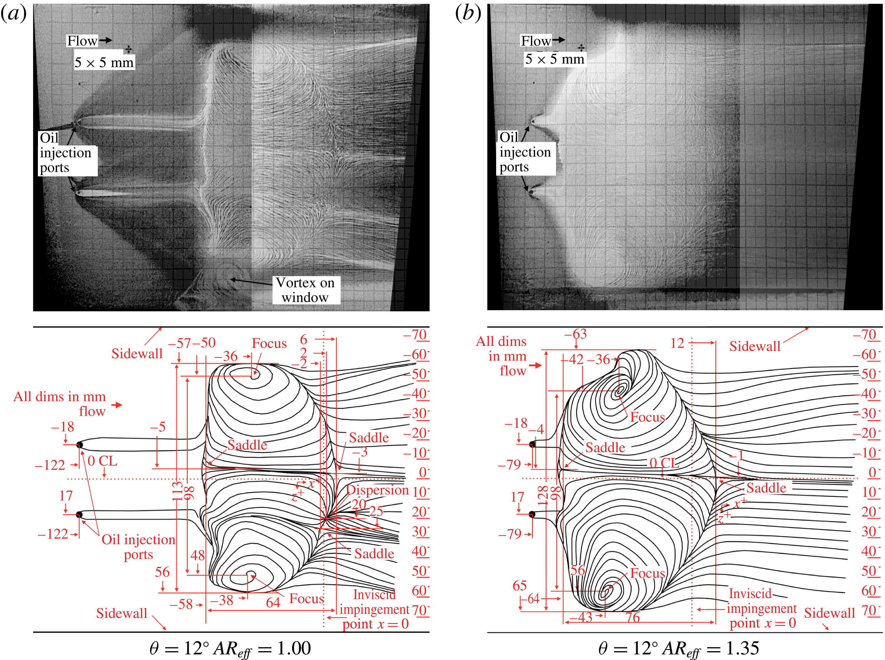
Figure 11. Flow separation region topology for no. 1: SG12T23,
![]() $AR_{eff}=1.00$
–
$AR_{eff}=1.00$
–
![]() $1.35$
.
$1.35$
.
Figure 11 shows the effect of
![]() $AR_{eff}$
on the topology of the separated region on the wind tunnel floor, as seen through the use of surface oil flow visualisation. Images for
$AR_{eff}$
on the topology of the separated region on the wind tunnel floor, as seen through the use of surface oil flow visualisation. Images for
![]() $AR_{eff}=1.00$
and
$AR_{eff}=1.00$
and
![]() $1.35$
are shown in figures 11(a) and 11(b) respectively. It should be noted that
$1.35$
are shown in figures 11(a) and 11(b) respectively. It should be noted that
![]() $AR_{eff}=1.35$
was used instead of
$AR_{eff}=1.35$
was used instead of
![]() $1.38$
due to the fact that the initial injection of oil causes a temporary flow disturbance, and a reduction in
$1.38$
due to the fact that the initial injection of oil causes a temporary flow disturbance, and a reduction in
![]() $AR_{eff}$
is required to avoid wind tunnel un-start.
$AR_{eff}$
is required to avoid wind tunnel un-start.
Inspection of figure 11(a)
![]() $(AR_{eff}=1.00)$
reveals many notable features. Most apparent is the large region of reversed flow, bounded by the upstream accumulation of oil mixture in a largely stream-normal direction and the downstream concave line of streamline branching. With the theoretical inviscid impingement point of the incident shock marking the
$(AR_{eff}=1.00)$
reveals many notable features. Most apparent is the large region of reversed flow, bounded by the upstream accumulation of oil mixture in a largely stream-normal direction and the downstream concave line of streamline branching. With the theoretical inviscid impingement point of the incident shock marking the
![]() $x=0$
axis and the tunnel centreline marking the
$x=0$
axis and the tunnel centreline marking the
![]() $z=0$
axis, the area is bounded by
$z=0$
axis, the area is bounded by
![]() $-58<x<6$
mm and
$-58<x<6$
mm and
![]() $-57<z<56$
mm. Within this region, there exist six critical points: two focus points, three saddle points and one dispersion node. The arrangement of these points and the general topography is similar to the ‘owl-face’ separated flow pattern described by Perry & Chong (Reference Perry and Chong1987). The stream-normal width of the separated region as measured from the outer edges of these vortices is
$-57<z<56$
mm. Within this region, there exist six critical points: two focus points, three saddle points and one dispersion node. The arrangement of these points and the general topography is similar to the ‘owl-face’ separated flow pattern described by Perry & Chong (Reference Perry and Chong1987). The stream-normal width of the separated region as measured from the outer edges of these vortices is
![]() $113$
mm. Two saddle points exist at
$113$
mm. Two saddle points exist at
![]() $(x,z)=(6,-3)$
mm and
$(x,z)=(6,-3)$
mm and
![]() $(x,z)=(-2,25)$
mm and a third at approximately
$(x,z)=(-2,25)$
mm and a third at approximately
![]() $(x,z)=(-58,-5)$
mm. The locations of these saddle points demonstrate that there is a small amount of asymmetry in the separation topology, in that one would expect them to be evenly distributed about the centreline (
$(x,z)=(-58,-5)$
mm. The locations of these saddle points demonstrate that there is a small amount of asymmetry in the separation topology, in that one would expect them to be evenly distributed about the centreline (
![]() $z=0$
mm). In between the two downstream saddle points is a dispersion node, i.e. a node with streamlines flowing away located at
$z=0$
mm). In between the two downstream saddle points is a dispersion node, i.e. a node with streamlines flowing away located at
![]() $(x,z)=(2,20)$
mm. The shock-induced separation begins at a roughly stream-normal lateral line along
$(x,z)=(2,20)$
mm. The shock-induced separation begins at a roughly stream-normal lateral line along
![]() $x=-58$
mm. Flow reattachment occurs along the curved line that begins and ends tangent to the outer edges of the two vortices (i.e.
$x=-58$
mm. Flow reattachment occurs along the curved line that begins and ends tangent to the outer edges of the two vortices (i.e.
![]() $(x,z)=(-36,-57)$
mm and
$(x,z)=(-36,-57)$
mm and
![]() $(x,z)=(-38,56)$
mm). The apex of this curve, which represents the furthest downstream reattachment point, is actually the saddle point located at
$(x,z)=(-38,56)$
mm). The apex of this curve, which represents the furthest downstream reattachment point, is actually the saddle point located at
![]() $(x,z)=(6,-3)$
mm, yielding a centreline streamwise separation length of
$(x,z)=(6,-3)$
mm, yielding a centreline streamwise separation length of
![]() $64$
mm.
$64$
mm.
It should be noted that the desire to accurately represent the extent of the separated region in this study has led to a definition of a ‘centreline separation length’ that both may not be the largest streamwise length present and may not exist exactly on the wind tunnel centreline. The definition used in this study is the distance between the apex of the curved reattachment line (which is typically close to the wind tunnel centreline) and an average separation line (mostly straight in a lateral direction). It is believed that this definition gives the best insight into the size of the separated region and very closely correlates with SWBLI size.
Figure 11(b)
![]() $(AR_{eff}=1.35)$
shows many of the same features as figure 11(a). However, the centreline streamwise length of the separation region has grown considerably to
$(AR_{eff}=1.35)$
shows many of the same features as figure 11(a). However, the centreline streamwise length of the separation region has grown considerably to
![]() $76$
mm (
$76$
mm (
![]() ${\approx}19\,\%$
). This growth in separation length is in agreement with the observations made with the schlieren photography and PIV, namely that the size of the interaction and hence the length of the separation bubble grows with increasing
${\approx}19\,\%$
). This growth in separation length is in agreement with the observations made with the schlieren photography and PIV, namely that the size of the interaction and hence the length of the separation bubble grows with increasing
![]() $AR_{eff}$
. Furthermore, the total number of critical points has been reduced to four, with the disappearance of one saddle point and the dispersion node along the reattachment line. The remaining saddle point on the reattachment line has moved now almost directly onto the tunnel centreline. The two counter-rotating vortices remain the same distance apart, but are skewed towards one side of the wind tunnel. A bulge in the topology pattern, at approximately
$AR_{eff}$
. Furthermore, the total number of critical points has been reduced to four, with the disappearance of one saddle point and the dispersion node along the reattachment line. The remaining saddle point on the reattachment line has moved now almost directly onto the tunnel centreline. The two counter-rotating vortices remain the same distance apart, but are skewed towards one side of the wind tunnel. A bulge in the topology pattern, at approximately
![]() $(x,z)=(-30,-63)$
mm, appears to have pushed the vortex at
$(x,z)=(-30,-63)$
mm, appears to have pushed the vortex at
![]() $(x,z)=(-36,-42)$
mm towards centreline. However, the root cause for this lateral shift is unknown.
$(x,z)=(-36,-42)$
mm towards centreline. However, the root cause for this lateral shift is unknown.
3.4 The role of the expansion fan
In the preceding sections, it was seen how an increase in
![]() $AR_{eff}$
resulted in transition between RR-SWBLI and MR-SWBLI without requiring an increase in incident shock strength. As
$AR_{eff}$
resulted in transition between RR-SWBLI and MR-SWBLI without requiring an increase in incident shock strength. As
![]() $AR_{eff}$
is increased for the configuration in this study, the relative orientation of the SWBLI and the expansion fan emanating from the underside of the shock generator is altered. To examine the effect of expansion fan proximity on the SWBLI, we investigate the mechanisms that can affect it. The placement of the expansion fan can be affected not only through a change in
$AR_{eff}$
is increased for the configuration in this study, the relative orientation of the SWBLI and the expansion fan emanating from the underside of the shock generator is altered. To examine the effect of expansion fan proximity on the SWBLI, we investigate the mechanisms that can affect it. The placement of the expansion fan can be affected not only through a change in
![]() $AR_{eff}$
, but it can be physically and virtually shifted as well by varying the shock generator thickness and the rounding of the expansion fan corner respectively.
$AR_{eff}$
, but it can be physically and virtually shifted as well by varying the shock generator thickness and the rounding of the expansion fan corner respectively.
Figure 12 shows the effect of varying the shock generator thickness on the SWBLI. The test configurations in figure 12 are identical in every way except for the shock generator thickness (i.e. identical flow deflection angles, identical inviscid incident shock impingement points and identical inflow boundary layer parameters). As the shock generator thickness is reduced from
![]() $23.8$
mm to
$23.8$
mm to
![]() $19.4$
mm and then to
$19.4$
mm and then to
![]() $15.0$
mm, the expansion fan origin location changes from
$15.0$
mm, the expansion fan origin location changes from
![]() $e_{0}=(-51.2,126.2)$
to
$e_{0}=(-51.2,126.2)$
to
![]() $(-71.9,130.6)$
to
$(-71.9,130.6)$
to
![]() $(-92.6,135.0)$
respectively. This results in a progressive shift upstream and stream-normal (away from the wind tunnel floor) in each case of
$(-92.6,135.0)$
respectively. This results in a progressive shift upstream and stream-normal (away from the wind tunnel floor) in each case of
![]() $\unicode[STIX]{x0394}x=-20.7,\unicode[STIX]{x0394}y=4.4$
mm, with the overall effect of bringing the expansion fan first characteristic and impingement point closer to the SWBLI. The result of this is that the overall size of the SWBLI is observed to reduce as the expansion fan is moved closer to the SWBLI. The case presented in figure 12(a) is the same as that presented in figure 7(a), which represented an RR and thus was classified as an Edney type I interference (RR-SWBLI). As the expansion fan is moved forward in figure 12(b,c), the triple point can be seen to reduce in height above the wind tunnel floor. However, there is no change in the general organisation of the SWBLI structure. As such, the classification of RR-SWBLI remains the same for all three SWBLIs. Apparent in the figure and in agreement with the reduction in size of the SWBLI, the separation point noticeably moves downstream as the expansion fan origin is moved upstream, which is indicative of a decrease in the streamwise extent of the separated region.
$\unicode[STIX]{x0394}x=-20.7,\unicode[STIX]{x0394}y=4.4$
mm, with the overall effect of bringing the expansion fan first characteristic and impingement point closer to the SWBLI. The result of this is that the overall size of the SWBLI is observed to reduce as the expansion fan is moved closer to the SWBLI. The case presented in figure 12(a) is the same as that presented in figure 7(a), which represented an RR and thus was classified as an Edney type I interference (RR-SWBLI). As the expansion fan is moved forward in figure 12(b,c), the triple point can be seen to reduce in height above the wind tunnel floor. However, there is no change in the general organisation of the SWBLI structure. As such, the classification of RR-SWBLI remains the same for all three SWBLIs. Apparent in the figure and in agreement with the reduction in size of the SWBLI, the separation point noticeably moves downstream as the expansion fan origin is moved upstream, which is indicative of a decrease in the streamwise extent of the separated region.

Figure 12. Schlieren photographs showing the effect of expansion fan placement on incident–reflected SWBLIs for (a) no. 1: SG12T23, (b) no. 3: SG12T19 and (c) no. 4: SG12T15 (
![]() $M_{0}=2$
,
$M_{0}=2$
,
![]() $\unicode[STIX]{x1D703}=12^{\circ }$
,
$\unicode[STIX]{x1D703}=12^{\circ }$
,
![]() $AR_{eff}=1.00$
).
$AR_{eff}=1.00$
).
Photographs of the separated region topology with accompanying streamline schematic diagrams for all three cases can be seen in figure 13. All three cases feature boundary layer separation, although the overall size of the separated region is reduced as the expansion fan is moved upstream. The primary indication of this is the streamwise separation length, which is reduced from
![]() $64$
to
$64$
to
![]() $49$
to
$49$
to
![]() $38$
mm. Figure 13(a) is the same as figure 11(a), which featured six critical points: two focus points, three saddle points and one dispersion node. As the expansion fan is moved upstream in the other two cases (figure 13
b,c), all six critical points persist, although their relative positions vary. The movement of the critical points is associated with an increase in the overall asymmetry of the separated region (either side of centreline). With the initial change in thickness from
$38$
mm. Figure 13(a) is the same as figure 11(a), which featured six critical points: two focus points, three saddle points and one dispersion node. As the expansion fan is moved upstream in the other two cases (figure 13
b,c), all six critical points persist, although their relative positions vary. The movement of the critical points is associated with an increase in the overall asymmetry of the separated region (either side of centreline). With the initial change in thickness from
![]() $23.8$
mm to
$23.8$
mm to
![]() $19.4$
mm, the saddle point along the separation line at
$19.4$
mm, the saddle point along the separation line at
![]() $(x,z)=(-58,-5)$
mm in figure 13(a) appears in an entirely different place, moving
$(x,z)=(-58,-5)$
mm in figure 13(a) appears in an entirely different place, moving
![]() $23$
mm to the other side of the centreline at
$23$
mm to the other side of the centreline at
![]() $(x,z)=(-45,18)$
mm in figure 13(b). This movement of the separation saddle point has a large effect on the streamlines in the centre of the separated region, disrupting their path and drawing in those in close proximity to the saddle point. The saddle points and dispersion node along the reattachment line maintain their local arrangement, although the saddle point originally located at
$(x,z)=(-45,18)$
mm in figure 13(b). This movement of the separation saddle point has a large effect on the streamlines in the centre of the separated region, disrupting their path and drawing in those in close proximity to the saddle point. The saddle points and dispersion node along the reattachment line maintain their local arrangement, although the saddle point originally located at
![]() $(x,z)=(6,-3)$
mm in figure 13(a) has also moved to the other side of the centreline in figure 13(b), though to a lesser degree than the movement of the saddle point on the separation line. The counter-rotating vortices originally centred at
$(x,z)=(6,-3)$
mm in figure 13(a) has also moved to the other side of the centreline in figure 13(b), though to a lesser degree than the movement of the saddle point on the separation line. The counter-rotating vortices originally centred at
![]() $(x,z)=(-36,-50)$
mm and
$(x,z)=(-36,-50)$
mm and
![]() $(x,z)=(-38,48)$
mm in figure 13(a) have shifted slightly further apart (from 98 to 100 mm) in figure 13(b), and the distance between the vortex centre and the outer edge has increased, resulting in a larger separation width (from 113 to 119 mm).
$(x,z)=(-38,48)$
mm in figure 13(a) have shifted slightly further apart (from 98 to 100 mm) in figure 13(b), and the distance between the vortex centre and the outer edge has increased, resulting in a larger separation width (from 113 to 119 mm).
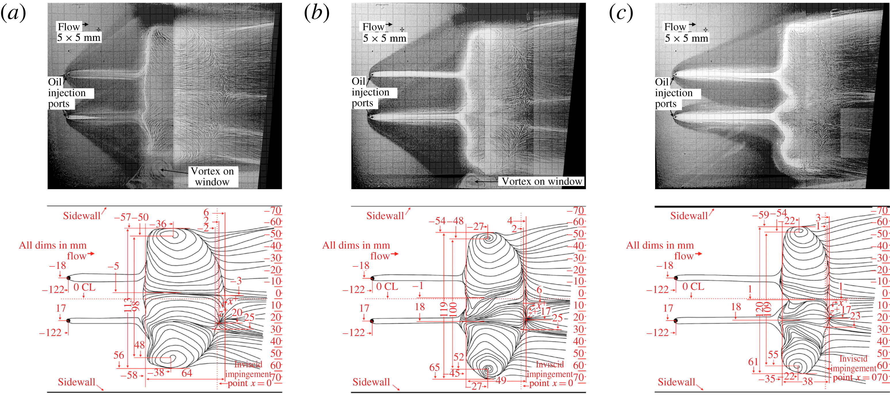
Figure 13. Flow separation topology showing the effect of expansion fan placement on (a) no. 1: SG12T23 (thickness
![]() $=$
23.8 mm), (b) no. 3: SG12T19 (thickness
$=$
23.8 mm), (b) no. 3: SG12T19 (thickness
![]() $=$
19.4 mm) and (c) no. 4: SG12T15 (thickness
$=$
19.4 mm) and (c) no. 4: SG12T15 (thickness
![]() $=$
15.0 mm) (
$=$
15.0 mm) (
![]() $M_{0}=2$
,
$M_{0}=2$
,
![]() $\unicode[STIX]{x1D703}=12^{\circ }$
,
$\unicode[STIX]{x1D703}=12^{\circ }$
,
![]() $AR_{eff}=1.00$
; not to scale with figure 12).
$AR_{eff}=1.00$
; not to scale with figure 12).
When the expansion fan is moved still further upstream, as is the case in figure 13(c), the separated region topology remains largely the same as in the previous case (figure 13
b). However, the separation length decreases further and the side vortices shift
![]() $9$
mm further apart, although this shift is accommodated without a significant change in the overall width of the separated region (119 versus 120 mm). The saddle point along the separation line remains in the same location in figure 13(c) as in figure 13(b), although the disturbance caused to the adjacent streamlines has increased, most notably with a dent in the separation line around
$9$
mm further apart, although this shift is accommodated without a significant change in the overall width of the separated region (119 versus 120 mm). The saddle point along the separation line remains in the same location in figure 13(c) as in figure 13(b), although the disturbance caused to the adjacent streamlines has increased, most notably with a dent in the separation line around
![]() $z=1$
mm and to a lesser extent at
$z=1$
mm and to a lesser extent at
![]() $z=35$
mm in figure 13(c). This arrangement is indicative of an overall weaker separated region that may be on the verge of necking down at these points and forming distinct separation cells.
$z=35$
mm in figure 13(c). This arrangement is indicative of an overall weaker separated region that may be on the verge of necking down at these points and forming distinct separation cells.
Figures 14 and 15 show the impact that rounding the corner on the
![]() $23.8$
mm thick shock generator has on the expansion fan placement. As with a change in shock generator thickness, both figures 14(a) and 14(b) have identical flow deflection angles, inviscid impingement points and inflow boundary layer parameters.
$23.8$
mm thick shock generator has on the expansion fan placement. As with a change in shock generator thickness, both figures 14(a) and 14(b) have identical flow deflection angles, inviscid impingement points and inflow boundary layer parameters.
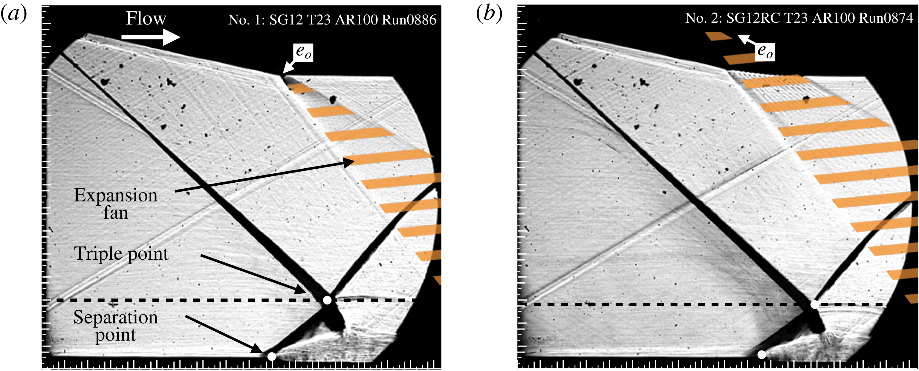
Figure 14. Schlieren photographs showing the effect of corner rounding (
![]() $M_{0}=2$
,
$M_{0}=2$
,
![]() $\unicode[STIX]{x1D703}=12^{\circ }$
,
$\unicode[STIX]{x1D703}=12^{\circ }$
,
![]() $AR_{eff}=1.00$
, thickness
$AR_{eff}=1.00$
, thickness
![]() $=$
23.8 mm): (a) no. 1: SG12 T23 straight corner; (b) no. 2: SG12RC T23 rounded corner.
$=$
23.8 mm): (a) no. 1: SG12 T23 straight corner; (b) no. 2: SG12RC T23 rounded corner.
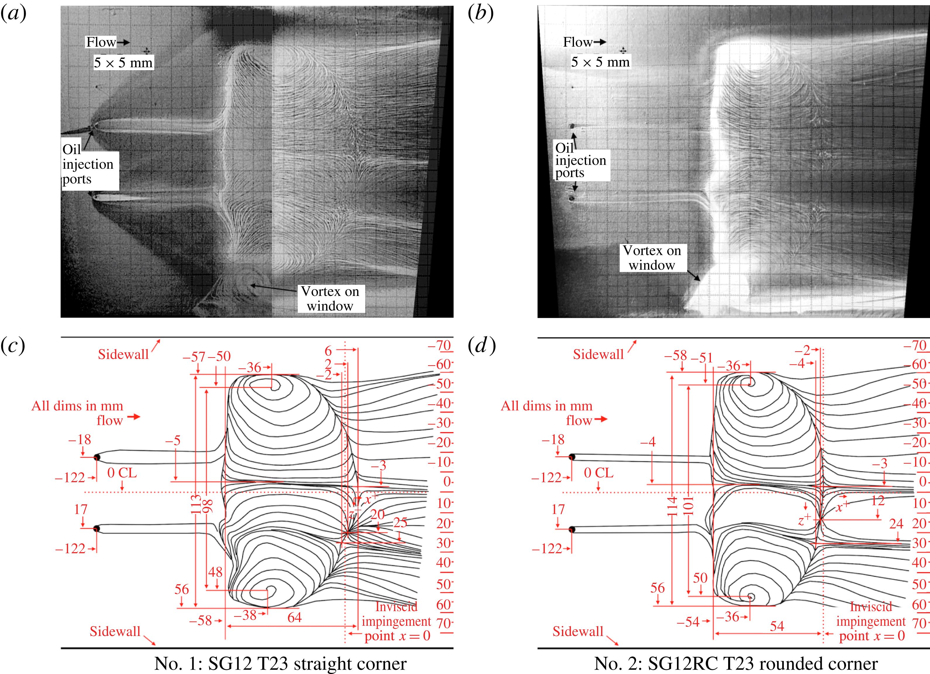
Figure 15. Flow separation topology showing the effect of corner rounding on separated region topology (
![]() $M_{0}=2$
,
$M_{0}=2$
,
![]() $\unicode[STIX]{x1D703}=12^{\circ }$
,
$\unicode[STIX]{x1D703}=12^{\circ }$
,
![]() $AR_{eff}=1.00$
).
$AR_{eff}=1.00$
).
Relative to the expansion fan origin
![]() $(e_{0})$
in figure 14(a), the corner rounding has virtually shifted
$(e_{0})$
in figure 14(a), the corner rounding has virtually shifted
![]() $e_{0}$
by
$e_{0}$
by
![]() $\unicode[STIX]{x0394}x\approx -31$
mm,
$\unicode[STIX]{x0394}x\approx -31$
mm,
![]() $\unicode[STIX]{x0394}y\approx 28$
mm in figure 14(b), which results in an upstream shift in the expansion fan first characteristic impingement. This upstream movement yields a result that is qualitatively similar to those seen in figures 12 and 13, namely an RR-SWBLI where the triple point height has decreased, the overall size of the SWBLI has decreased and the point of boundary layer separation has moved downstream. Figure 15 shows that the six critical points are present and their arrangement remains largely unchanged, save for the dispersion node, which has shifted towards the centreline by
$\unicode[STIX]{x0394}y\approx 28$
mm in figure 14(b), which results in an upstream shift in the expansion fan first characteristic impingement. This upstream movement yields a result that is qualitatively similar to those seen in figures 12 and 13, namely an RR-SWBLI where the triple point height has decreased, the overall size of the SWBLI has decreased and the point of boundary layer separation has moved downstream. Figure 15 shows that the six critical points are present and their arrangement remains largely unchanged, save for the dispersion node, which has shifted towards the centreline by
![]() $8$
mm. The vortex separation has grown slightly (from 98 to 101 mm) in the rounded corner case, although the separation width is nearly the same (from 113 to 114 mm). The largest change in the topology is the separation length, which has reduced from 64 to 54 mm in the rounded corner case, which is consistent with the trend observed in figure 13.
$8$
mm. The vortex separation has grown slightly (from 98 to 101 mm) in the rounded corner case, although the separation width is nearly the same (from 113 to 114 mm). The largest change in the topology is the separation length, which has reduced from 64 to 54 mm in the rounded corner case, which is consistent with the trend observed in figure 13.
Figure 16 shows the effect of shock generator thickness and corner rounding on the static pressure distribution through the separated region. All four pressure profiles share the same inviscid incident shock impingement point. The separation and reattachment points obtained from the surface oil flow visualisations along with the approximate first characteristic of the expansion fan impingement are all annotated for each profile. Each profile has varying degrees of spatial resolution due to data acquisition constraints. The lowest spatial resolution for any profile is
![]() $5$
mm, but all initially feature
$5$
mm, but all initially feature
![]() $1$
mm resolution around the point of separation and through most of the separated region.
$1$
mm resolution around the point of separation and through most of the separated region.
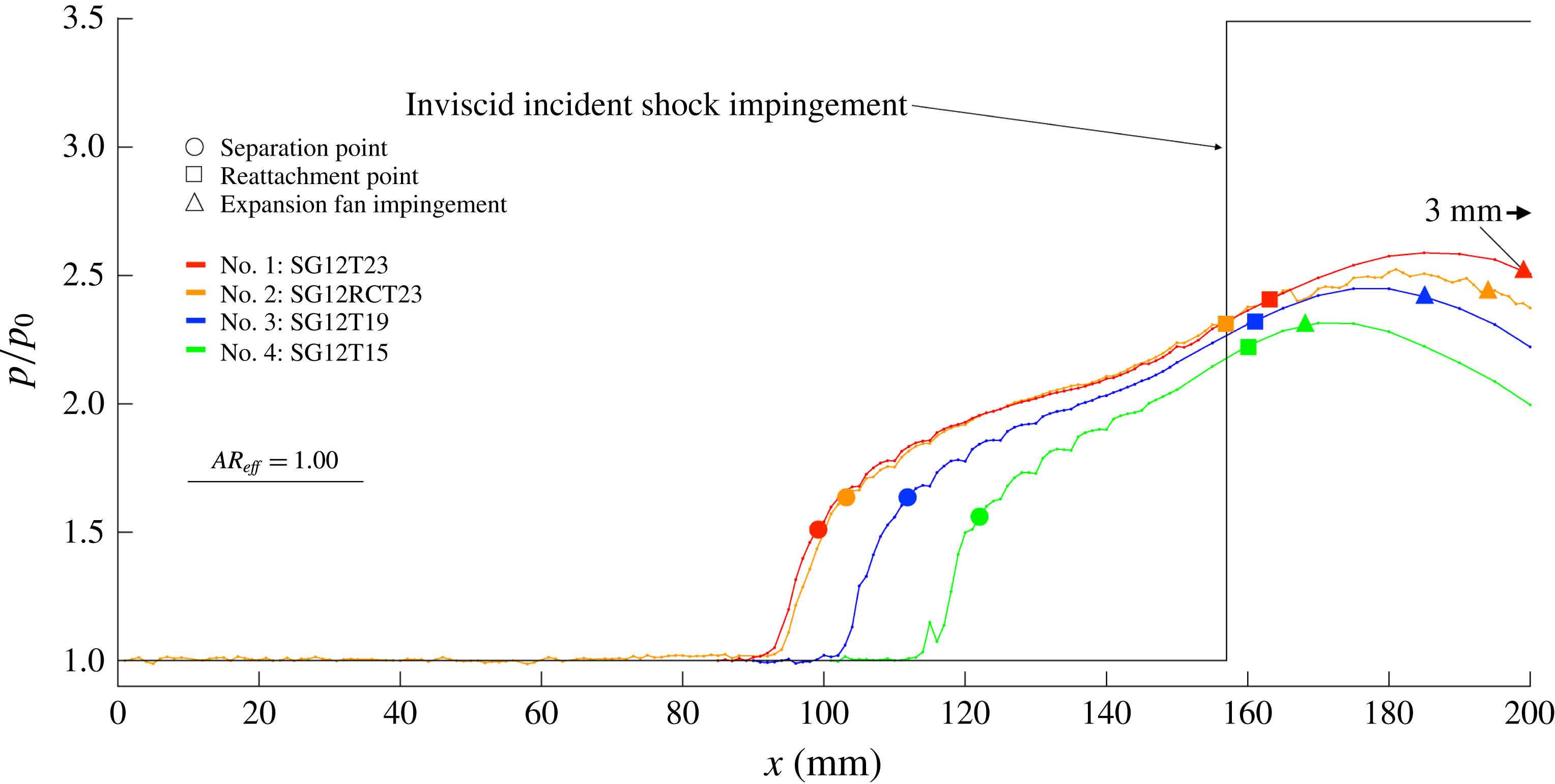
Figure 16. Mean normalised static wall pressure distributions with varying shock generator thickness (
![]() $M_{0}=2$
,
$M_{0}=2$
,
![]() $\unicode[STIX]{x1D703}=12^{\circ }$
,
$\unicode[STIX]{x1D703}=12^{\circ }$
,
![]() $AR_{eff}=1.00$
).
$AR_{eff}=1.00$
).
All four profiles exhibit a uniform inflow pressure followed by a sharp two-step rise across the SWBLI and finally a drop in pressure due to the incident expansion fan. Taking the no. 1: SG12T23 shock generator as a baseline in figure 16, three characteristic changes are observed as the expansion fan impingement point is moved progressively upstream for the test case no. 2: SG12RCT23, followed by nos. 3: SG12T19 and 4: SG12T15. Perhaps the most notable characteristic is that the reattachment points for all three cases appear to remain nearly fixed relative to the baseline case (although the reattachment point for case no. 2: SG12RCT23 shifts upstream slightly). In addition, the separation point moves downstream, effectively reducing the streamwise extent of the pressure rise up to reattachment. Lastly, both the pressure rise to separation and the pressure rise to reattachment change slightly but do not exhibit a clear trend.
All of the profiles exhibit a repeating pattern of concave bumps immediately downstream of the separation point in figure 16. This effect is attributed to the spanwise staggered arrangement of static tappings that was necessary to achieve 1 mm streamwise resolution, an assertion that is supported by the fact that the bumps repeat every
![]() $5$
mm and are spatially aligned between the different test cases rather than relative to any feature of the pressure profile (e.g. separation point). This illustrates the three-dimensionality inherent in the topology of the separated regions in figures 13 and 15, and hints at a few additional characteristics that are out of the plotted data plane. First, any appearance of this kind of bump is evidence of some variation in the lateral (
$5$
mm and are spatially aligned between the different test cases rather than relative to any feature of the pressure profile (e.g. separation point). This illustrates the three-dimensionality inherent in the topology of the separated regions in figures 13 and 15, and hints at a few additional characteristics that are out of the plotted data plane. First, any appearance of this kind of bump is evidence of some variation in the lateral (
![]() $z$
-direction) pressure profile. Furthermore, this variation in the lateral pressure profile is not present prior to the initial pressure rise associated with the separated region. For example, the profile in figure 16 for no. 4: SG12T15 shows little spanwise variation until
$z$
-direction) pressure profile. Furthermore, this variation in the lateral pressure profile is not present prior to the initial pressure rise associated with the separated region. For example, the profile in figure 16 for no. 4: SG12T15 shows little spanwise variation until
![]() ${\approx}115$
mm, where a spike is observed. This spike is not an error and is, in fact, indicative of a spanwise pressure mismatch in the region
${\approx}115$
mm, where a spike is observed. This spike is not an error and is, in fact, indicative of a spanwise pressure mismatch in the region
![]() $114<x<117$
mm. After the overall initial increase in lateral pressure variation through separation, all four profiles exhibit a reduction of lateral pressure variation as the profiles reach roughly midway between the points of separation and reattachment.
$114<x<117$
mm. After the overall initial increase in lateral pressure variation through separation, all four profiles exhibit a reduction of lateral pressure variation as the profiles reach roughly midway between the points of separation and reattachment.
3.5 The relation between expansion fan position and effective aspect ratio
In § 3.1, it was seen that SWBLI size, triple point height, separation size and separation length all grow with an increase in
![]() $AR_{eff}$
, while in the previous section, it has been shown these same features all grow with an increase in the distance between the expansion fan and the SWBLI. These characteristics are summarised in table 5. To compare these two observed trends, we now attempt to collate the results from all test cases into one plot.
$AR_{eff}$
, while in the previous section, it has been shown these same features all grow with an increase in the distance between the expansion fan and the SWBLI. These characteristics are summarised in table 5. To compare these two observed trends, we now attempt to collate the results from all test cases into one plot.
Table 5. Summary of interaction dimensions for all configurations tested (
![]() $W_{sep}$
is the separation width).
$W_{sep}$
is the separation width).
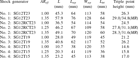
Experiments with the four shock generators seen previously in this study (nos. 1: SG12T23, 2: SG12RCT23, 3: SG12T19 and 4: SG12T15) were conducted at
![]() $AR_{eff}=1.35$
to yield four additional test cases where the upstream first characteristic expansion fan impingement points moved downstream relative to the incident shock inviscid impingement point. This provided four entirely new expansion fan separation cases to compare with those of the previous section. In addition to these eight cases, two additional cases were added by positioning shock generators nos. 2: SG12RCT23 and 4: SG12T15 at
$AR_{eff}=1.35$
to yield four additional test cases where the upstream first characteristic expansion fan impingement points moved downstream relative to the incident shock inviscid impingement point. This provided four entirely new expansion fan separation cases to compare with those of the previous section. In addition to these eight cases, two additional cases were added by positioning shock generators nos. 2: SG12RCT23 and 4: SG12T15 at
![]() $AR_{eff}=1.25$
. Figure 17 conveys the domain for all of the expansion fan impingement points relative to the inviscid incident shock impingement point by aligning all 10 of these cases along their respective inviscid incident shock impingement locations. Key dimensions from figure 17 relating to the expansion fan origin and impingement point for all 10 cases are presented in table 3.
$AR_{eff}=1.25$
. Figure 17 conveys the domain for all of the expansion fan impingement points relative to the inviscid incident shock impingement point by aligning all 10 of these cases along their respective inviscid incident shock impingement locations. Key dimensions from figure 17 relating to the expansion fan origin and impingement point for all 10 cases are presented in table 3.
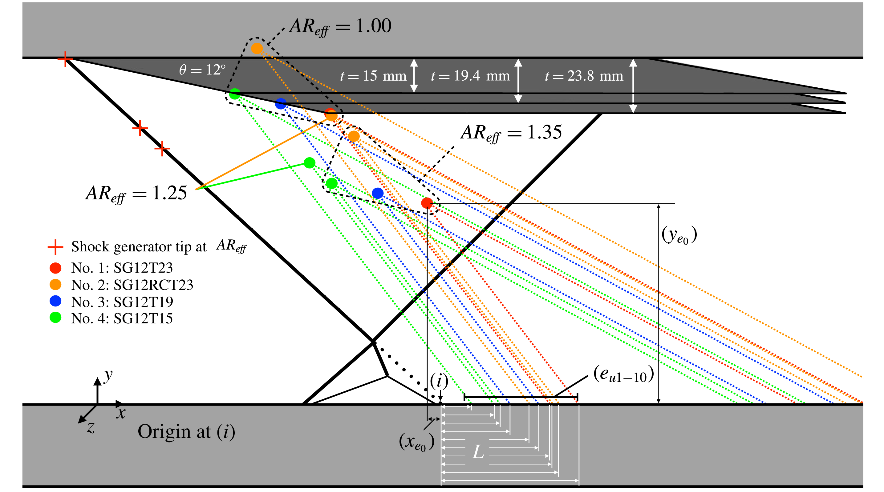
Figure 17. Schematic diagram of expansion fan placement with varying thickness and
![]() $AR_{eff}$
.
$AR_{eff}$
.
Figure 18 presents the static wall pressure distribution for the low- and high-
![]() $AR_{eff}$
test cases. The positions of the separation, reattachment, inviscid incident shock impingement and expansion fan impingement points are all annotated for each pressure profile. In the figure, it can be observed that an increase in
$AR_{eff}$
test cases. The positions of the separation, reattachment, inviscid incident shock impingement and expansion fan impingement points are all annotated for each pressure profile. In the figure, it can be observed that an increase in
![]() $AR_{eff}$
results in an upstream shift of all of the profiles due to the change of the inviscid shock impingement point (
$AR_{eff}$
results in an upstream shift of all of the profiles due to the change of the inviscid shock impingement point (
![]() $117$
mm for
$117$
mm for
![]() $AR_{eff}=1.35$
and
$AR_{eff}=1.35$
and
![]() $157$
mm for
$157$
mm for
![]() $AR_{eff}=1.00$
). However, close inspection reveals that this upstream shift in the profiles is not enough to account for the total movement in the separation point in each profile. Hence, each of the four profiles displays an increase in the streamwise extent that is consistent with the relationship between
$AR_{eff}=1.00$
). However, close inspection reveals that this upstream shift in the profiles is not enough to account for the total movement in the separation point in each profile. Hence, each of the four profiles displays an increase in the streamwise extent that is consistent with the relationship between
![]() $AR_{eff}$
and separation length (
$AR_{eff}$
and separation length (
![]() $L_{sep}$
) previously observed in figure 11.
$L_{sep}$
) previously observed in figure 11.
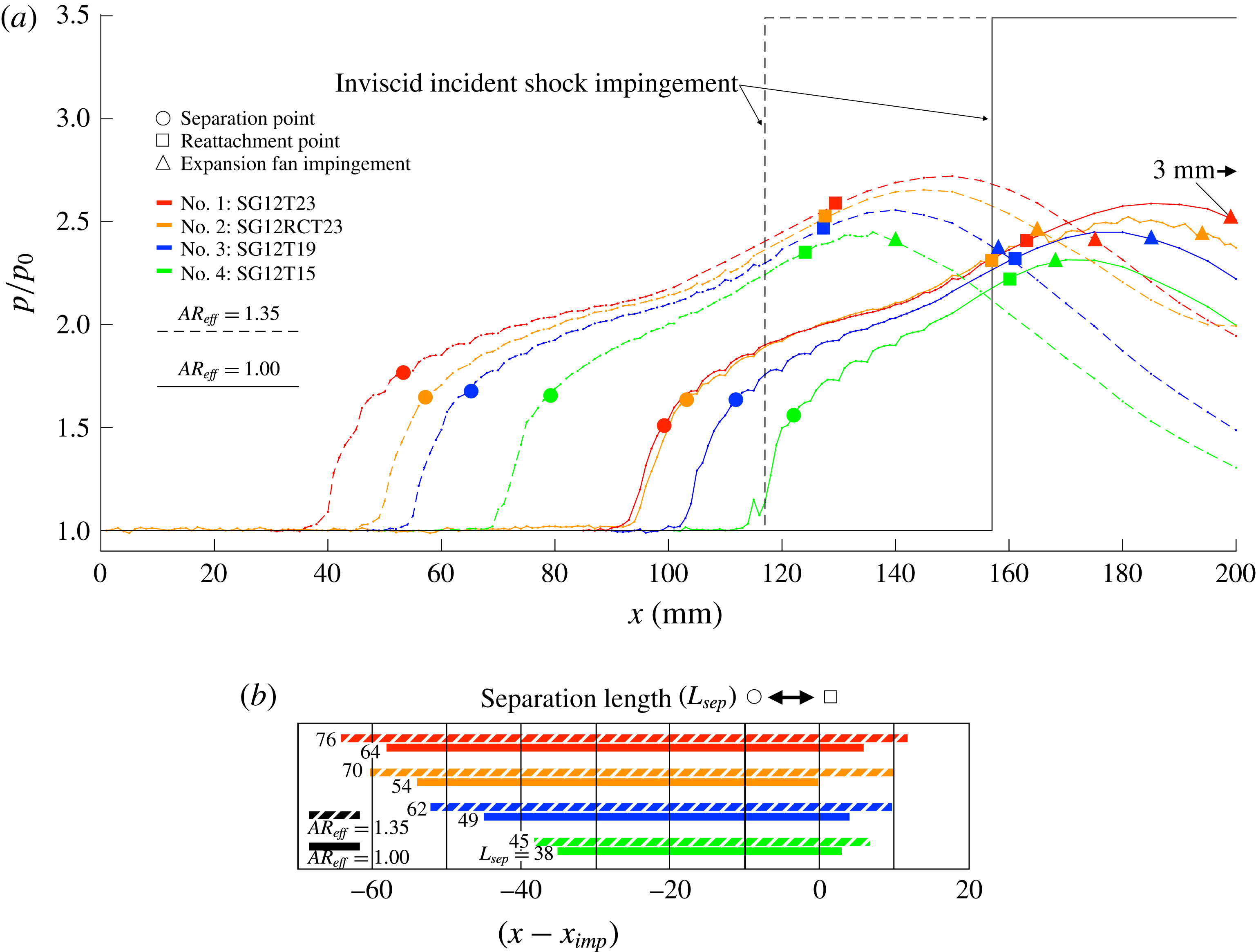
Figure 18. (a) Mean normalised static wall pressure distributions with varying shock generator thickness and aspect ratio. (b) Separation length aligned on the inviscid shock impingement point.
Figure 18(b) presents this information in a line plot aligned on the inviscid shock impingement point. It clearly shows the trend of an increase in the streamwise extent with an increase in shock generator thickness and
![]() $AR_{eff}$
. It further demonstrates that the growth of the separated region is accomplished mostly due to an upstream movement in the separation point, with only a relatively small downstream shift in the reattachment points.
$AR_{eff}$
. It further demonstrates that the growth of the separated region is accomplished mostly due to an upstream movement in the separation point, with only a relatively small downstream shift in the reattachment points.
The pressure rise to separation at
![]() $AR_{eff}=1.35$
is very similar for all cases, whereas the pressure rise to reattachment progressively grows for all four profiles with the downstream movement of the expansion fan. This is consistent with the concept provided by free interaction theory of splitting the pressure rise at separation from the pressure rise at reattachment, considering the pressure rise to separation to be completely unaffected by the downstream shock or the downstream pressure rise to reattachment. Therefore, if some change has occurred that causes the separation bubble to increase in size, requiring a greater pressure rise to reattachment, the pressure rise to separation will be unchanged and will not contribute to the process. As Délery (Reference Délery, Babinsky and Harvey2011) explained, the ability for the flow to reattach is directly related to the amount of flow momentum available at the reattachment point, and a shear layer, originating at the separation point, obtains this momentum from the free stream. As such, if a greater momentum is required at reattachment, the shear layer will need to interact with the free stream over a greater distance, increasing the amount of flow momentum imparted from the free stream. Délery (Reference Délery, Babinsky and Harvey2011) contended that this is accomplished by a separation point that moves further upstream.
$AR_{eff}=1.35$
is very similar for all cases, whereas the pressure rise to reattachment progressively grows for all four profiles with the downstream movement of the expansion fan. This is consistent with the concept provided by free interaction theory of splitting the pressure rise at separation from the pressure rise at reattachment, considering the pressure rise to separation to be completely unaffected by the downstream shock or the downstream pressure rise to reattachment. Therefore, if some change has occurred that causes the separation bubble to increase in size, requiring a greater pressure rise to reattachment, the pressure rise to separation will be unchanged and will not contribute to the process. As Délery (Reference Délery, Babinsky and Harvey2011) explained, the ability for the flow to reattach is directly related to the amount of flow momentum available at the reattachment point, and a shear layer, originating at the separation point, obtains this momentum from the free stream. As such, if a greater momentum is required at reattachment, the shear layer will need to interact with the free stream over a greater distance, increasing the amount of flow momentum imparted from the free stream. Délery (Reference Délery, Babinsky and Harvey2011) contended that this is accomplished by a separation point that moves further upstream.
The movement in separation and reattachment points as well as the separation length relative to the distance between the expansion fan impingement point and the inviscid incident shock impingement point are all plotted in figure 19 with accompanying linear regressions. Figure 19(a) suggests a direct correlation between expansion fan placement and separation length. Figure 19(b) confirms the trend seen in figure 18(a), that the growth in separation length is primarily a result of upstream movement of the separation point, in agreement with Délery (Reference Délery, Babinsky and Harvey2011).
Also of importance and apparent in both figures is that in the range of expansion fan impingement separation
![]() $(L)$
investigated, at no point was independence between the expansion fan position and the length of the separated region achieved. Furthermore, the range of
$(L)$
investigated, at no point was independence between the expansion fan position and the length of the separated region achieved. Furthermore, the range of
![]() $L$
investigated is close to the maximum that could be achieved with the geometries investigated. For example, if the expansion fan were pushed further upstream for the limiting case of no. 4: SG12T15 at
$L$
investigated is close to the maximum that could be achieved with the geometries investigated. For example, if the expansion fan were pushed further upstream for the limiting case of no. 4: SG12T15 at
![]() $AR_{eff}=1.00$
, the first characteristic of the expansion fan would come into direct contact with the SWBLI. Conversely, if the expansion fan were pushed further downstream for the limiting case of no. 1: SG12T23 at
$AR_{eff}=1.00$
, the first characteristic of the expansion fan would come into direct contact with the SWBLI. Conversely, if the expansion fan were pushed further downstream for the limiting case of no. 1: SG12T23 at
![]() $AR_{eff}=1.35$
, an incident–reflected SWBLI would cease to exist beyond
$AR_{eff}=1.35$
, an incident–reflected SWBLI would cease to exist beyond
![]() $AR_{eff}=1.38$
as it would surpass the theoretical limit in this case for a stable shock reflection due to the fact that the reflected shock wave impingement point would have moved far enough upstream to coincide with the expansion fan origin. In the current study, a normal shock wave was observed to form instantaneously at the leading tip in front of the shock generator upon exceeding this limit.
$AR_{eff}=1.38$
as it would surpass the theoretical limit in this case for a stable shock reflection due to the fact that the reflected shock wave impingement point would have moved far enough upstream to coincide with the expansion fan origin. In the current study, a normal shock wave was observed to form instantaneously at the leading tip in front of the shock generator upon exceeding this limit.
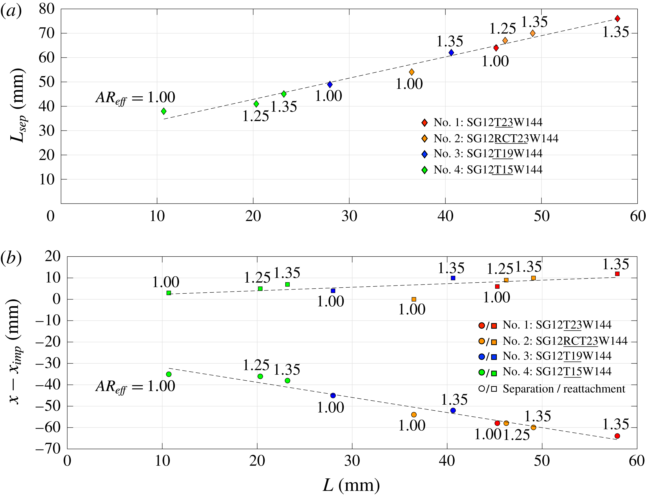
Figure 19. Effect of expansion fan impingement separation (
![]() $L$
) on (a) separation length (
$L$
) on (a) separation length (
![]() $L_{sep}$
) and (b) incident shock impingement distance (
$L_{sep}$
) and (b) incident shock impingement distance (
![]() $x-x_{imp}$
) of the separation and reattachment points.
$x-x_{imp}$
) of the separation and reattachment points.
In the past, studies have attempted to reconcile such variations in experimental and numerical data by applying some scaling parameter to a diverse set of reported results. One such study, by Souverein et al. (Reference Souverein, Bakker and Dupont2013), attempted to quantify the variation of interaction length with shock strength, Mach number, geometry and Reynolds number. This scaling analysis introduced by Souverein et al. (Reference Souverein, Bakker and Dupont2013) only depends on the free-stream Mach number and flow deflection angle, given by
where
![]() $\unicode[STIX]{x0394}P$
is the shock intensity,
$\unicode[STIX]{x0394}P$
is the shock intensity,
![]() $q_{0}$
is the dynamic pressure and
$q_{0}$
is the dynamic pressure and
![]() $k$
is a constant chosen such that it is one at the onset of separation. In addition to this, Souverein et al. (Reference Souverein, Bakker and Dupont2013) derived a scaled interaction length, given by
$k$
is a constant chosen such that it is one at the onset of separation. In addition to this, Souverein et al. (Reference Souverein, Bakker and Dupont2013) derived a scaled interaction length, given by
and
The scaled interaction length (
![]() $L^{\ast }$
) is a function of the free-stream Mach number (
$L^{\ast }$
) is a function of the free-stream Mach number (
![]() $M_{0}$
), flow deflection angle (
$M_{0}$
), flow deflection angle (
![]() $\unicode[STIX]{x1D703}$
), compressible displacement thickness (
$\unicode[STIX]{x1D703}$
), compressible displacement thickness (
![]() $\unicode[STIX]{x1D6FF}_{c}^{\ast }$
) and length of the interaction (
$\unicode[STIX]{x1D6FF}_{c}^{\ast }$
) and length of the interaction (
![]() $L_{int}$
), which Souverein et al. (Reference Souverein, Bakker and Dupont2013) define as the distance between the mean location of the separation shock foot and the inviscid incident shock impingement point. Thus, it should be pointed out that
$L_{int}$
), which Souverein et al. (Reference Souverein, Bakker and Dupont2013) define as the distance between the mean location of the separation shock foot and the inviscid incident shock impingement point. Thus, it should be pointed out that
![]() $L_{int}$
differs from the separation length
$L_{int}$
differs from the separation length
![]() $L_{sep}$
discussed above, and for all of the cases in this study,
$L_{sep}$
discussed above, and for all of the cases in this study,
![]() $L_{int}\leqslant L_{sep}$
(see table 5).
$L_{int}\leqslant L_{sep}$
(see table 5).
When the scaled interaction length is taken together with
![]() $S_{e}^{\ast }$
, this enables Souverein et al. (Reference Souverein, Bakker and Dupont2013) to classify the separation states over a range of interactions of varying strength, Mach and Reynolds numbers created by both ramp and incident–reflected SWBLIs. This range of interactions appears grouped in figure 20 for
$S_{e}^{\ast }$
, this enables Souverein et al. (Reference Souverein, Bakker and Dupont2013) to classify the separation states over a range of interactions of varying strength, Mach and Reynolds numbers created by both ramp and incident–reflected SWBLIs. This range of interactions appears grouped in figure 20 for
![]() $S_{e}^{\ast }<2.0$
. It can be seen in the figure that almost all of the various studies (
$S_{e}^{\ast }<2.0$
. It can be seen in the figure that almost all of the various studies (
![]() $S_{e}^{\ast }<2.0$
) collapse well onto a trend line when quantified by these two scaled parameters. Souverein et al. (Reference Souverein, Bakker and Dupont2013) contended that the remaining scatter of the studies
$S_{e}^{\ast }<2.0$
) collapse well onto a trend line when quantified by these two scaled parameters. Souverein et al. (Reference Souverein, Bakker and Dupont2013) contended that the remaining scatter of the studies
![]() $S_{e}^{\ast }<2.0$
is largely due to differences in experimental set-up. Since the range of
$S_{e}^{\ast }<2.0$
is largely due to differences in experimental set-up. Since the range of
![]() $L$
obtained in the present study represents nearly the full range achievable given the free-stream conditions and flow deflection angle investigated, the results presented here are uniquely positioned to give an estimate of the bounds of the observed scatter in the study of Souverein et al. (Reference Souverein, Bakker and Dupont2013).
$L$
obtained in the present study represents nearly the full range achievable given the free-stream conditions and flow deflection angle investigated, the results presented here are uniquely positioned to give an estimate of the bounds of the observed scatter in the study of Souverein et al. (Reference Souverein, Bakker and Dupont2013).
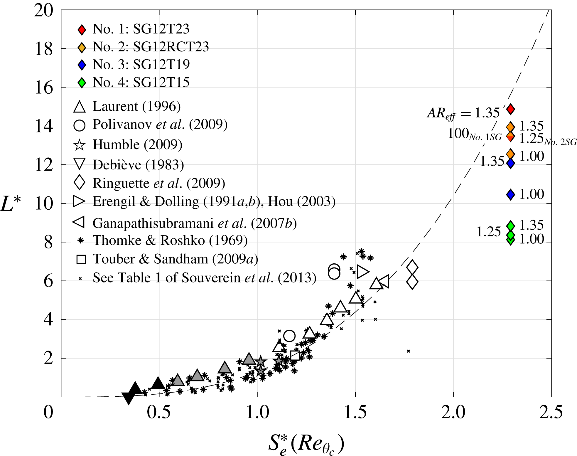
Figure 20. Interaction length and shock strength scaling across ramp and incident–reflected interactions of varying Mach and Reynolds numbers (based on compressible momentum thickness) from Souverein et al. (Reference Souverein, Bakker and Dupont2013) for separated (open), incipient (grey) and attached (black) SWBLIs. The dashed line is a best fit line (
![]() $a\ast x^{b}$
, where
$a\ast x^{b}$
, where
![]() $a=1.3$
,
$a=1.3$
,
![]() $b=3$
). The reader is referred to the paper by Souverein et al. (Reference Souverein, Bakker and Dupont2013) for full details of the references that the experimental data are taken from.
$b=3$
). The reader is referred to the paper by Souverein et al. (Reference Souverein, Bakker and Dupont2013) for full details of the references that the experimental data are taken from.
The results from the present study appear in figure 20 grouped along a line through
![]() $S_{e}^{\ast }=2.47$
and spread across
$S_{e}^{\ast }=2.47$
and spread across
![]() $15.29<L^{\ast }<27.95$
. These values of
$15.29<L^{\ast }<27.95$
. These values of
![]() $S_{e}^{\ast }$
and
$S_{e}^{\ast }$
and
![]() $L^{\ast }$
greatly expand the envelope of the plot farther than any of the studies considered by Souverein et al. (Reference Souverein, Bakker and Dupont2013). This observed scatter of the data from this study when plotted against the model suggests the following. (1) Expansion fan placement, relative to the SWBLI, has a significant effect on the scatter in the model. The result that lies closest to the model trend line corresponds with the test case that features the greatest separation between the expansion fan and the SWBLI. This results in a trend that correlates the closeness of the expansion fan to the SWBLI with a departure from the model trend line of Souverein et al. (Reference Souverein, Bakker and Dupont2013). (2) Since the range of expansion fan placement (
$L^{\ast }$
greatly expand the envelope of the plot farther than any of the studies considered by Souverein et al. (Reference Souverein, Bakker and Dupont2013). This observed scatter of the data from this study when plotted against the model suggests the following. (1) Expansion fan placement, relative to the SWBLI, has a significant effect on the scatter in the model. The result that lies closest to the model trend line corresponds with the test case that features the greatest separation between the expansion fan and the SWBLI. This results in a trend that correlates the closeness of the expansion fan to the SWBLI with a departure from the model trend line of Souverein et al. (Reference Souverein, Bakker and Dupont2013). (2) Since the range of expansion fan placement (
![]() $L$
) represents nearly the full range possible, the observed scatter of the data from this study may be, to the first order, a good approximation of the bounds of scatter within the model.
$L$
) represents nearly the full range possible, the observed scatter of the data from this study may be, to the first order, a good approximation of the bounds of scatter within the model.
It should be noted that a value of
![]() $k=2.5$
was used based upon the criteria outlined by Souverein et al. (Reference Souverein, Bakker and Dupont2013), but that the Reynolds number of this study (
$k=2.5$
was used based upon the criteria outlined by Souverein et al. (Reference Souverein, Bakker and Dupont2013), but that the Reynolds number of this study (
![]() $Re_{\unicode[STIX]{x1D703}}=10124$
; see table 1) lies significantly close to the switch criterion between the two values of
$Re_{\unicode[STIX]{x1D703}}=10124$
; see table 1) lies significantly close to the switch criterion between the two values of
![]() $k$
. In addition to this, incorporation of the data from the present study requires a relatively long-range extrapolation of the trend line of Souverein et al. (Reference Souverein, Bakker and Dupont2013), which is in itself a significant source of uncertainty.
$k$
. In addition to this, incorporation of the data from the present study requires a relatively long-range extrapolation of the trend line of Souverein et al. (Reference Souverein, Bakker and Dupont2013), which is in itself a significant source of uncertainty.
3.6 Free interaction theory
The free interaction theory of Chapman et al. (Reference Chapman, Kuehn and Larson1958) states that the initial pressure rise to the point of boundary layer separation is governed solely by the flow properties at the onset of separation and is thus independent of the overall configuration or the agency through which separation is induced. This suggests that the pressure profiles taken at various
![]() $AR_{eff}$
and with different shock generator thicknesses should all exhibit near identical initial pressure rises to separation. To compare the initial SWBLI-induced pressure rise of each of the profiles in figure 18, they have been replotted in figure 21, aligned so as to match the initial pressure rise of the no. 1: SG12T23
$AR_{eff}$
and with different shock generator thicknesses should all exhibit near identical initial pressure rises to separation. To compare the initial SWBLI-induced pressure rise of each of the profiles in figure 18, they have been replotted in figure 21, aligned so as to match the initial pressure rise of the no. 1: SG12T23
![]() $AR_{eff}=1.35$
case.
$AR_{eff}=1.35$
case.
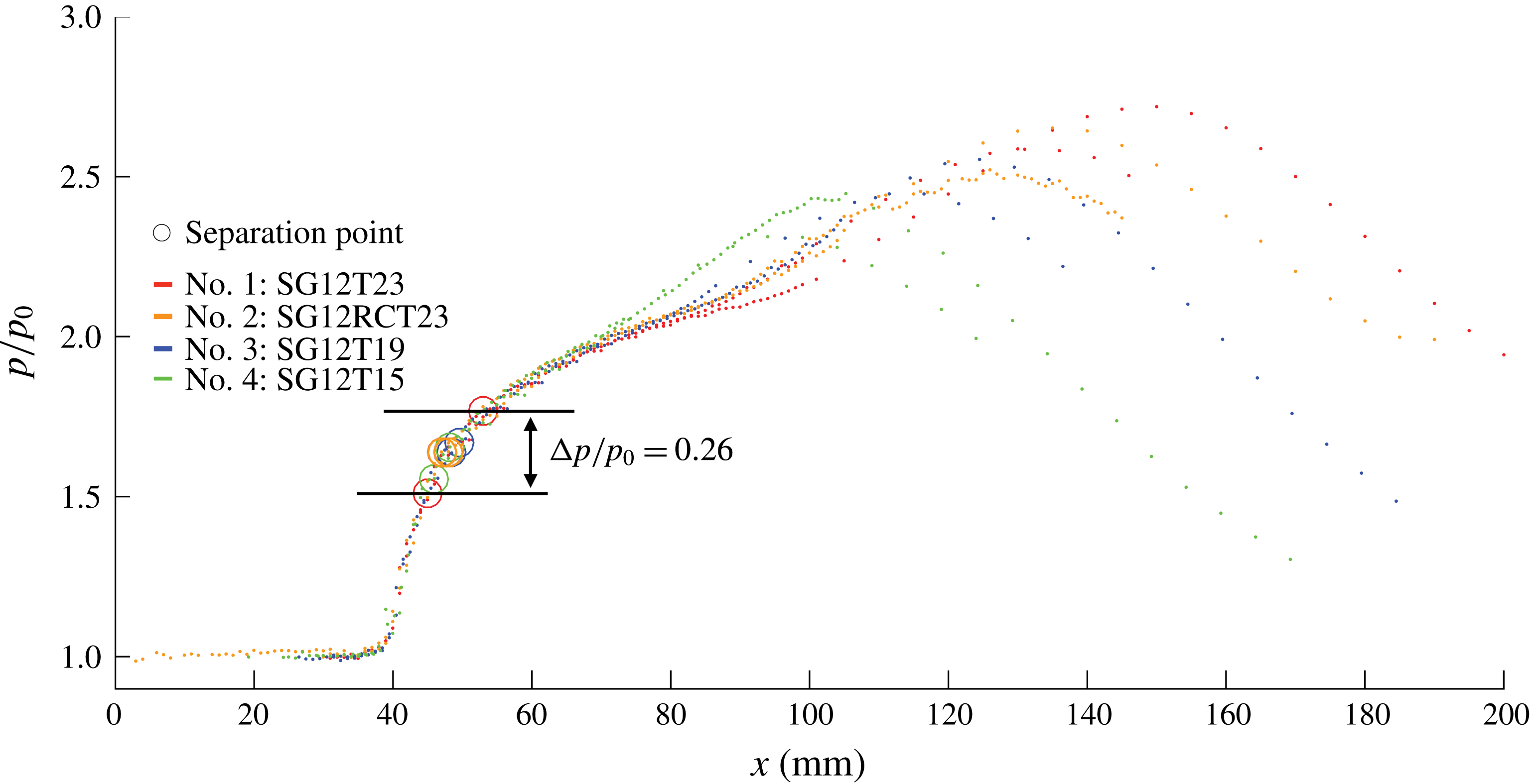
Figure 21. Mean normalised static wall pressure distributions of varying thickness and aspect ratio aligned on initial pressure rise to separation.
Figure 21 shows that all eight profiles do indeed follow an almost identical initial pressure rise up to the point of separation, after which they begin to diverge. However, the points of separation for each configuration are not identical, instead being spread over a range of
![]() $8$
mm in streamwise extent and occurring at pressures in the range
$8$
mm in streamwise extent and occurring at pressures in the range
![]() $0.182<p/p_{t}<0.213$
. This compares with the theoretical value of 0.198 proposed by Erdos & Pallone (Reference Erdos and Pallone1962), who suggested that the pressure rise during the free interaction process is governed by
$0.182<p/p_{t}<0.213$
. This compares with the theoretical value of 0.198 proposed by Erdos & Pallone (Reference Erdos and Pallone1962), who suggested that the pressure rise during the free interaction process is governed by
where the universal correlation function
![]() $F(\overline{x})$
is defined by
$F(\overline{x})$
is defined by
where
Here,
![]() $\unicode[STIX]{x1D70F}$
is the shear stress,
$\unicode[STIX]{x1D70F}$
is the shear stress,
![]() $\unicode[STIX]{x1D70F}_{w0}$
is the wall shear stress at the interaction origin (
$\unicode[STIX]{x1D70F}_{w0}$
is the wall shear stress at the interaction origin (
![]() $x_{0}$
),
$x_{0}$
),
![]() $\unicode[STIX]{x1D6FF}_{0}^{\ast }$
is the boundary layer displacement thickness and
$\unicode[STIX]{x1D6FF}_{0}^{\ast }$
is the boundary layer displacement thickness and
![]() $L_{rise}$
is the length characteristic of the streamwise extent of free interaction.
$L_{rise}$
is the length characteristic of the streamwise extent of free interaction.
In figure 22, the universal correlation function
![]() $F(\overline{x})$
is evaluated for all eight cases of figure 21. Annotated on the figure with dashed lines are the values of
$F(\overline{x})$
is evaluated for all eight cases of figure 21. Annotated on the figure with dashed lines are the values of
![]() $F(\overline{x})$
at separation for each of the cases as well as the values proposed by Erdos & Pallone (Reference Erdos and Pallone1962) for
$F(\overline{x})$
at separation for each of the cases as well as the values proposed by Erdos & Pallone (Reference Erdos and Pallone1962) for
![]() $F(\overline{x})_{separation}=4.22$
and
$F(\overline{x})_{separation}=4.22$
and
![]() $F(\overline{x})_{plateau}=6.00$
for a turbulent flow. The reference point
$F(\overline{x})_{plateau}=6.00$
for a turbulent flow. The reference point
![]() $x_{f}$
in figure 22 is defined as the location on the curves where
$x_{f}$
in figure 22 is defined as the location on the curves where
![]() $F(\overline{x})=4.22$
.
$F(\overline{x})=4.22$
.
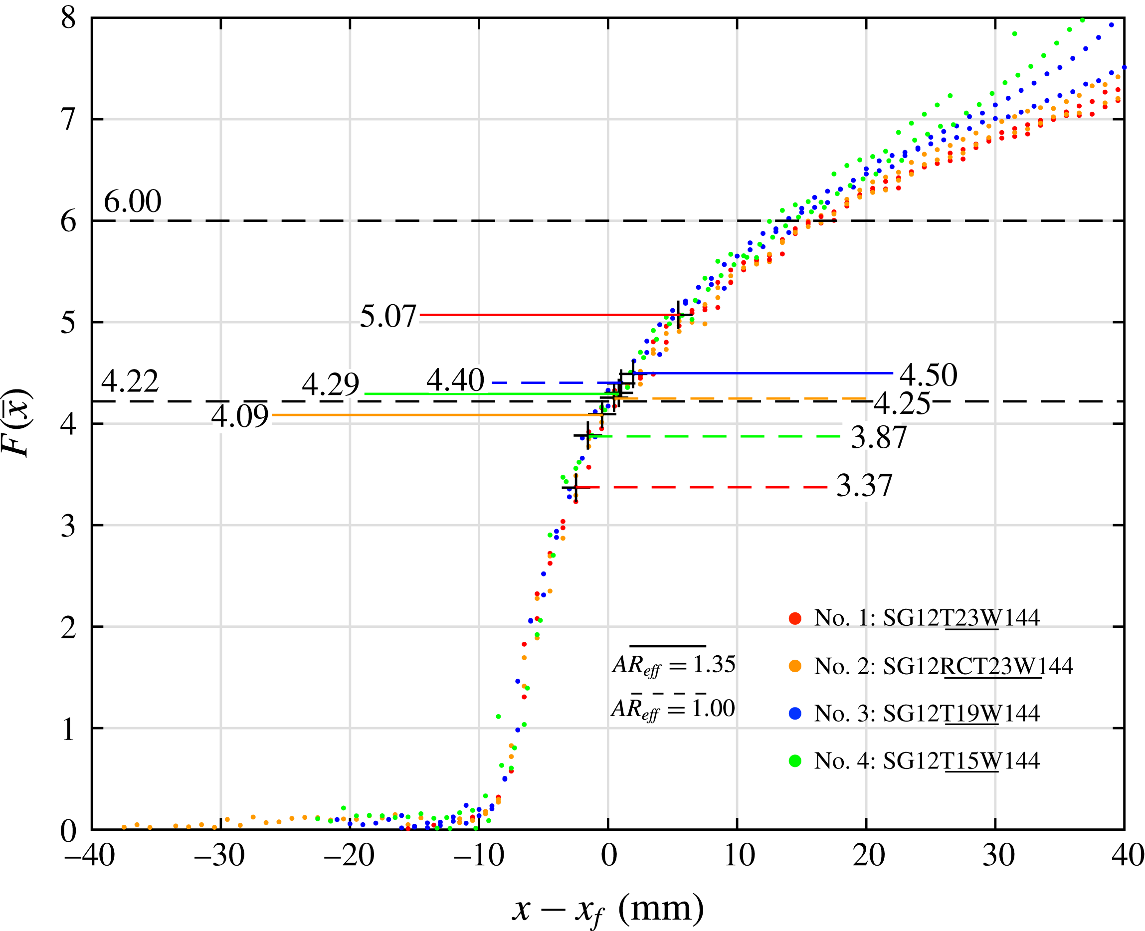
Figure 22. Universal correlation function evaluated for nos. 1: SG12T23, 2: SG12RCT23, 3: SG12T19 and 4: SG12T15;
![]() $AR_{eff}=1.00$
–
$AR_{eff}=1.00$
–
![]() $1.35$
.
$1.35$
.
Taking all profiles into account, the experimentally determined average value of
![]() $F(\overline{x})_{separation}$
for this study is
$F(\overline{x})_{separation}$
for this study is
![]() $4.23$
, in close agreement with the value
$4.23$
, in close agreement with the value
![]() $F(\overline{x})_{separation}=4.22$
proposed by Erdos & Pallone (Reference Erdos and Pallone1962). However, due to the relatively low strength of the interaction (i.e. pressure ratio), no meaningful pressure profile plateau was observed for any of the profiles in figure 22, and thus no experimentally determined values are annotated.
$F(\overline{x})_{separation}=4.22$
proposed by Erdos & Pallone (Reference Erdos and Pallone1962). However, due to the relatively low strength of the interaction (i.e. pressure ratio), no meaningful pressure profile plateau was observed for any of the profiles in figure 22, and thus no experimentally determined values are annotated.
3.7 Discussion of separation shock characteristics
In the numerical study of Matheis & Hickel (Reference Matheis and Hickel2015), it was observed that in an
![]() $M_{0}=2$
flow, if the flow deflection angle was increased (and thus the incident shock strength) beyond
$M_{0}=2$
flow, if the flow deflection angle was increased (and thus the incident shock strength) beyond
![]() $\unicode[STIX]{x1D703}=11^{\circ }$
, the mean separation shock angle remained nearly constant. Matheis & Hickel (Reference Matheis and Hickel2015) also contended that this behaviour is characteristic of the free interaction theory of Chapman et al. (Reference Chapman, Kuehn and Larson1958).
$\unicode[STIX]{x1D703}=11^{\circ }$
, the mean separation shock angle remained nearly constant. Matheis & Hickel (Reference Matheis and Hickel2015) also contended that this behaviour is characteristic of the free interaction theory of Chapman et al. (Reference Chapman, Kuehn and Larson1958).
In the present study, an RR-SWBLI is observed for
![]() $\unicode[STIX]{x1D703}=12^{\circ }$
at low
$\unicode[STIX]{x1D703}=12^{\circ }$
at low
![]() $AR_{eff}$
, while an MR-SWBLI is observed at high
$AR_{eff}$
, while an MR-SWBLI is observed at high
![]() $AR_{eff}$
, with the incident flow deflection held constant, and thus the strength of the incident oblique shock wave. From this, we reasonably conclude that the only mechanism for a sustained transition to MR is through an increase in the mean separation shock angle. To address this apparent contradiction between the results of this study and those of Matheis & Hickel (Reference Matheis and Hickel2015), we discuss the classic inviscid model for an incident–reflected SWBLI and propose a slightly altered representation that is consistent with the results seen in the previous sections.
$AR_{eff}$
, with the incident flow deflection held constant, and thus the strength of the incident oblique shock wave. From this, we reasonably conclude that the only mechanism for a sustained transition to MR is through an increase in the mean separation shock angle. To address this apparent contradiction between the results of this study and those of Matheis & Hickel (Reference Matheis and Hickel2015), we discuss the classic inviscid model for an incident–reflected SWBLI and propose a slightly altered representation that is consistent with the results seen in the previous sections.
The ‘classic’ inviscid model for an incident–reflected SWBLI with separation appears in figure 23. The isobaric shock-induced separated region
![]() $S{-}T{-}R$
is modelled as a physical obstruction requiring a sharp flow deflection much like a physical ramp. The sonic line of the boundary layer in a viscous model could serve as an acceptable proxy for the border of region
$S{-}T{-}R$
is modelled as a physical obstruction requiring a sharp flow deflection much like a physical ramp. The sonic line of the boundary layer in a viscous model could serve as an acceptable proxy for the border of region
![]() $S{-}T{-}R$
, such that outside of this region the flow is supersonic, allowing for the formation of shock waves. The separation shock angle
$S{-}T{-}R$
, such that outside of this region the flow is supersonic, allowing for the formation of shock waves. The separation shock angle
![]() $(\unicode[STIX]{x1D6FD}_{s})$
would then be dictated by the angle (
$(\unicode[STIX]{x1D6FD}_{s})$
would then be dictated by the angle (
![]() $\unicode[STIX]{x1D703}_{s}$
) of the upstream face of the isobaric region, modelled as a straight line
$\unicode[STIX]{x1D703}_{s}$
) of the upstream face of the isobaric region, modelled as a straight line
![]() $S{-}T$
, turning the flow parallel with this line, travelling unhindered until it reaches the transmitted shock (
$S{-}T$
, turning the flow parallel with this line, travelling unhindered until it reaches the transmitted shock (
![]() $C4$
) and an expansion fan, which turns the flow over the crest of the isobaric separated region. The idealised pressure profile of the classic model would feature a two-step pressure rise: one sharp pressure rise at point
$C4$
) and an expansion fan, which turns the flow over the crest of the isobaric separated region. The idealised pressure profile of the classic model would feature a two-step pressure rise: one sharp pressure rise at point
![]() $S$
and another sharp pressure rise at point
$S$
and another sharp pressure rise at point
![]() $R$
, with a plateau region between points
$R$
, with a plateau region between points
![]() $S$
and
$S$
and
![]() $R$
through the isobaric separated region.
$R$
through the isobaric separated region.
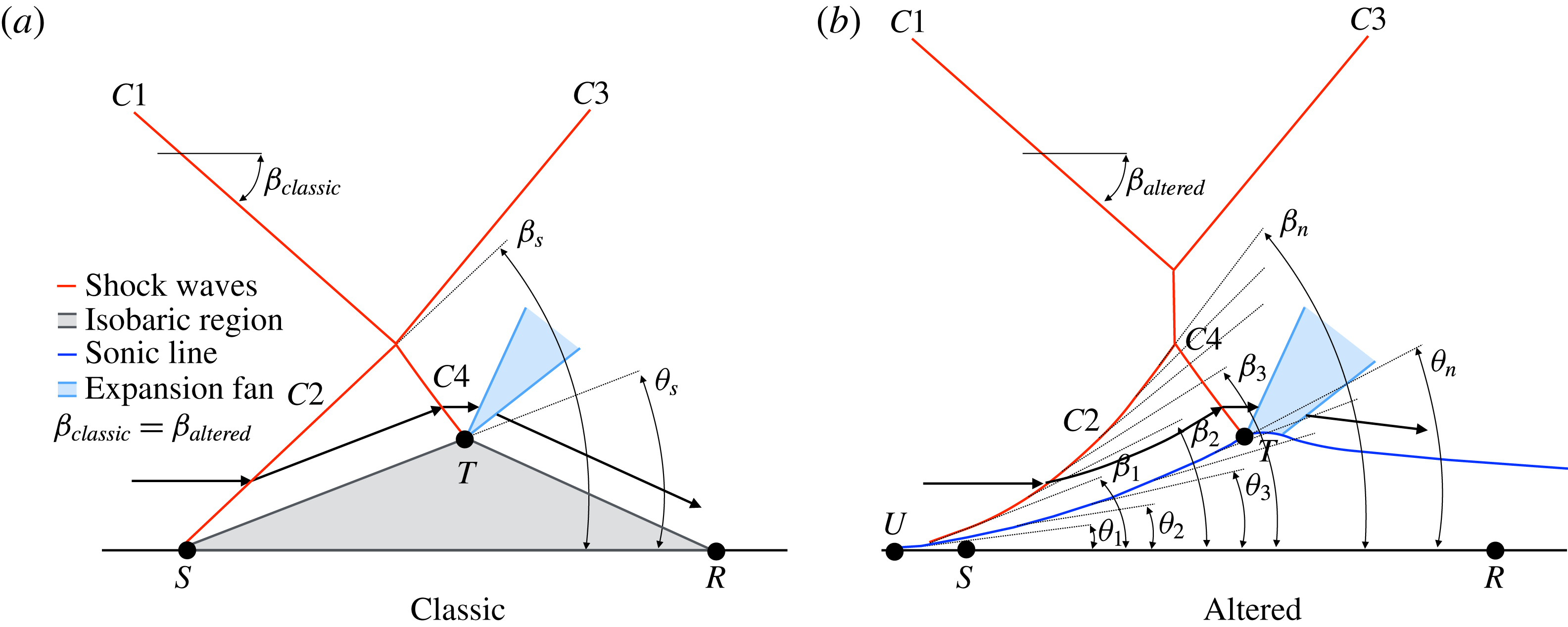
Figure 23. Classic inviscid model for incident–reflected SWBLI and an altered representation.
In reality, as seen in figures 11, 13 and 15, the separated region is in fact a highly three-dimensional region with significant streamwise and stream-normal variations even in a time-averaged sense. When time is taken into account, it is known that the separated region exhibits even greater variation. For example, Touber & Sandham (Reference Touber and Sandham2009) observed displacement of the separation and reattachment points over time as well as the breaking up and enhancement of the upstream section of the separation bubble, inducing translation and rotation in the separation shock. Matheis & Hickel (Reference Matheis and Hickel2015) observed that the separation shock angle fluctuated in the range of
![]() $\unicode[STIX]{x1D6FD}=39.50^{\circ }$
–
$\unicode[STIX]{x1D6FD}=39.50^{\circ }$
–
![]() $42.74^{\circ }$
for their
$42.74^{\circ }$
for their
![]() $\unicode[STIX]{x1D703}=13^{\circ }$
case, and attributed this to the fluctuations and inherent dynamics of the incoming turbulent boundary layer. The net result of this fluctuation in time of the separation shock angle and the relationship it has with the SWBLI as a whole can be better understood from the shock polar representation in figure 24 for the
$\unicode[STIX]{x1D703}=13^{\circ }$
case, and attributed this to the fluctuations and inherent dynamics of the incoming turbulent boundary layer. The net result of this fluctuation in time of the separation shock angle and the relationship it has with the SWBLI as a whole can be better understood from the shock polar representation in figure 24 for the
![]() $\unicode[STIX]{x1D703}=13^{\circ }$
case. In the figure, the separation shock polar originating from point 2 at
$\unicode[STIX]{x1D703}=13^{\circ }$
case. In the figure, the separation shock polar originating from point 2 at
![]() $\unicode[STIX]{x1D703}\approx 11.4^{\circ }$
is observed to grow and shrink with time. At some points in time, the two polars overlap and RR-SWBLI is observed, while at other points in time, the two polars pull apart and MR-SWBLI is observed. In the present study, when the arrangement of the shock generator
$\unicode[STIX]{x1D703}\approx 11.4^{\circ }$
is observed to grow and shrink with time. At some points in time, the two polars overlap and RR-SWBLI is observed, while at other points in time, the two polars pull apart and MR-SWBLI is observed. In the present study, when the arrangement of the shock generator
![]() $AR_{eff}$
and expansion fan placement is such as to allow for an MR-SWBLI to occur, it is likely that this fluctuation in time of the separation shock angle is the mechanism that triggers transition from RR-SWBLI to MR-SWBLI. Indeed, similar observations were made in the present study for the
$AR_{eff}$
and expansion fan placement is such as to allow for an MR-SWBLI to occur, it is likely that this fluctuation in time of the separation shock angle is the mechanism that triggers transition from RR-SWBLI to MR-SWBLI. Indeed, similar observations were made in the present study for the
![]() $\unicode[STIX]{x1D703}=12^{\circ }$
cases from the schlieren video taken, particularly in intermediate
$\unicode[STIX]{x1D703}=12^{\circ }$
cases from the schlieren video taken, particularly in intermediate
![]() $AR_{eff}$
around the point of transition. However, for reasons just discussed, it is difficult to assign a particular
$AR_{eff}$
around the point of transition. However, for reasons just discussed, it is difficult to assign a particular
![]() $AR_{eff}$
to the transition point as, over a range of intermediate
$AR_{eff}$
to the transition point as, over a range of intermediate
![]() $AR_{eff}$
, multiple transitions between RR-SWBLI and MR-SWBLI exist. It is important to reassure the reader, in light of this uncertainty, that the observed RR-SWBLI at low
$AR_{eff}$
, multiple transitions between RR-SWBLI and MR-SWBLI exist. It is important to reassure the reader, in light of this uncertainty, that the observed RR-SWBLI at low
![]() $AR_{eff}$
and the observed MR-SWBLI at high
$AR_{eff}$
and the observed MR-SWBLI at high
![]() $AR_{eff}$
in the
$AR_{eff}$
in the
![]() $\unicode[STIX]{x1D703}=12^{\circ }$
case are not transient and represent an average state change for the SWBLI. Evidence of this is provided in § 3.1 in figures 9(c) and 9(d), which clearly show RR-SWBLI at
$\unicode[STIX]{x1D703}=12^{\circ }$
case are not transient and represent an average state change for the SWBLI. Evidence of this is provided in § 3.1 in figures 9(c) and 9(d), which clearly show RR-SWBLI at
![]() $AR_{eff}=1.00$
and MR-SWBLI at
$AR_{eff}=1.00$
and MR-SWBLI at
![]() $AR_{eff}=1.38$
and are ensemble averages over 3.8 s.
$AR_{eff}=1.38$
and are ensemble averages over 3.8 s.
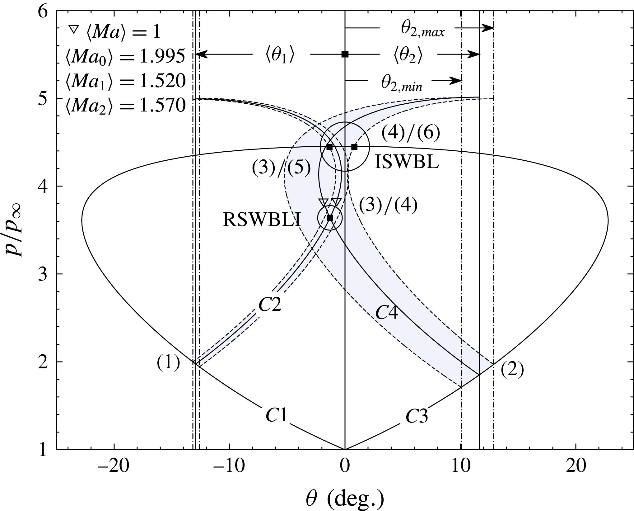
Figure 24. Shock polar for
![]() $\unicode[STIX]{x1D703}=13^{\circ }$
exhibiting separation shock variance from Matheis & Hickel (Reference Matheis and Hickel2015) (notation altered for consistency).
$\unicode[STIX]{x1D703}=13^{\circ }$
exhibiting separation shock variance from Matheis & Hickel (Reference Matheis and Hickel2015) (notation altered for consistency).
Furthermore, as mentioned in § 1.3, it is widely known that the inclusion of sidewalls can have large three-dimensional effects on the resulting flow (Bruce et al. Reference Bruce, Burton, Titchener and Babinsky2011; Burton & Babinsky Reference Burton and Babinsky2012; Babinsky et al. Reference Babinsky, Oorebeek and Cottingham2013; Benek et al. Reference Benek, Suchyta and Babinsky2013; Galbraith et al. Reference Galbraith, Turner, Orkwisr and Weil2013; Wang et al. Reference Wang, Sandham, Hu and Liu2015). We content that so-called three-dimensional effects, such as pressure disturbances generated by viscous flow phenomena in the tunnel corners, as reported by Babinsky et al. (Reference Babinsky, Oorebeek and Cottingham2013), may also contribute to the ‘non-canonical’ development of the separation bubble (and hence separation shock) at the tunnel centreline. The presence of additional compressive waves at the centreline downstream of the separation point would be consistent with a steepening of the front shock leg and an increase in the angle of flow separation. This is in contrast to the study of Matheis & Hickel (Reference Matheis and Hickel2015), which featured periodic boundary conditions and thus would not have these three-dimensional effects generated by corners.
Taking all of this into account, it is clear that the separation shock is dictated by the nature of a highly variable (in space and time) separated region and that the upstream facing section of the separated region
![]() $S{-}T$
is unlikely to be a straight line, as in the classic inviscid model, and is more likely to exhibit some amount of curvature at one or many points and will change over time. These concepts are not new and can be regarded as widely accepted. However, the appreciation of these concepts with regard to transition helps to explain the results seen in this study. Thus, a representation that incorporates these concepts appears in figure 23, labelled ‘altered’. In this representation, there exists shock-induced flow separation somewhere in the region of
$S{-}T$
is unlikely to be a straight line, as in the classic inviscid model, and is more likely to exhibit some amount of curvature at one or many points and will change over time. These concepts are not new and can be regarded as widely accepted. However, the appreciation of these concepts with regard to transition helps to explain the results seen in this study. Thus, a representation that incorporates these concepts appears in figure 23, labelled ‘altered’. In this representation, there exists shock-induced flow separation somewhere in the region of
![]() $S{-}T{-}R$
, which causes the sonic line to navigate up and around it and has a limited upstream influence as far as point
$S{-}T{-}R$
, which causes the sonic line to navigate up and around it and has a limited upstream influence as far as point
![]() $U$
. The supersonic flow above the sonic line that must navigate the obstruction posed by the separated region is turned by a separation shock. As the line
$U$
. The supersonic flow above the sonic line that must navigate the obstruction posed by the separated region is turned by a separation shock. As the line
![]() $U{-}T$
is not straight (it has been exaggerated for clarity), there exists not one value of
$U{-}T$
is not straight (it has been exaggerated for clarity), there exists not one value of
![]() $\unicode[STIX]{x1D703}$
but many values
$\unicode[STIX]{x1D703}$
but many values
![]() $\unicode[STIX]{x1D703}_{1}$
–
$\unicode[STIX]{x1D703}_{1}$
–
![]() $\unicode[STIX]{x1D703}_{n}$
progressively requiring the flow to turn by a greater amount. This flow turning will naturally occur through a separation shock
$\unicode[STIX]{x1D703}_{n}$
progressively requiring the flow to turn by a greater amount. This flow turning will naturally occur through a separation shock
![]() $\unicode[STIX]{x1D6FD}$
, but, as there are many values of
$\unicode[STIX]{x1D6FD}$
, but, as there are many values of
![]() $\unicode[STIX]{x1D703}$
, there will be many values of
$\unicode[STIX]{x1D703}$
, there will be many values of
![]() $\unicode[STIX]{x1D6FD}$
, and thus the separation shock will progressively turn
$\unicode[STIX]{x1D6FD}$
, and thus the separation shock will progressively turn
![]() $\unicode[STIX]{x1D6FD}_{1}$
–
$\unicode[STIX]{x1D6FD}_{1}$
–
![]() $\unicode[STIX]{x1D6FD}_{n}$
. This line has been drawn concave, but this is arbitrary, and it could be drawn convex, or any combination thereof. In this representation,
$\unicode[STIX]{x1D6FD}_{n}$
. This line has been drawn concave, but this is arbitrary, and it could be drawn convex, or any combination thereof. In this representation,
![]() $\unicode[STIX]{x1D6FD}_{1}$
could be small enough to permit RR-SWBLI, but here
$\unicode[STIX]{x1D6FD}_{1}$
could be small enough to permit RR-SWBLI, but here
![]() $\unicode[STIX]{x1D6FD}_{n}$
could have exceeded the maximum turning angle of the flow as required by the region immediately downstream of shock
$\unicode[STIX]{x1D6FD}_{n}$
could have exceeded the maximum turning angle of the flow as required by the region immediately downstream of shock
![]() $C3$
, resulting in MR-SWBLI.
$C3$
, resulting in MR-SWBLI.
If the time-average separation shock angle is dependent upon the entire time-averaged upstream facing section of the separation bubble (line
![]() $U{-}T$
), then for free interaction theory to dictate its mean angle, it would also need to dictate the entire line
$U{-}T$
), then for free interaction theory to dictate its mean angle, it would also need to dictate the entire line
![]() $U{-}T$
. This is possible for strong interactions. However, in this study, as mentioned in the previous section, no pressure plateau was observed for any of the interactions due to the relative weakness of the interaction. In this case, free interaction theory is only applicable up to the point of separation. This range of influence across the altered representation is presented in figure 25. In this figure, it can be seen that the separation shock influence region
$U{-}T$
. This is possible for strong interactions. However, in this study, as mentioned in the previous section, no pressure plateau was observed for any of the interactions due to the relative weakness of the interaction. In this case, free interaction theory is only applicable up to the point of separation. This range of influence across the altered representation is presented in figure 25. In this figure, it can be seen that the separation shock influence region
![]() $U{-}T$
and the free interaction region
$U{-}T$
and the free interaction region
![]() $U{-}S$
overlap, but that most of the separation shock influence region remains out of range of free interaction theory. Therefore, free interaction theory may be responsible for some initial contributions to the separation shock, as indicated in the figure for
$U{-}S$
overlap, but that most of the separation shock influence region remains out of range of free interaction theory. Therefore, free interaction theory may be responsible for some initial contributions to the separation shock, as indicated in the figure for
![]() $\unicode[STIX]{x1D703}_{1}$
and
$\unicode[STIX]{x1D703}_{1}$
and
![]() $\unicode[STIX]{x1D6FD}_{1}$
. However, it is unlikely that the rest of the line
$\unicode[STIX]{x1D6FD}_{1}$
. However, it is unlikely that the rest of the line
![]() $S{-}T$
, and with it
$S{-}T$
, and with it
![]() $\unicode[STIX]{x1D703}_{2}$
–
$\unicode[STIX]{x1D703}_{2}$
–
![]() $\unicode[STIX]{x1D703}_{n}$
and
$\unicode[STIX]{x1D703}_{n}$
and
![]() $\unicode[STIX]{x1D6FD}_{2}$
–
$\unicode[STIX]{x1D6FD}_{2}$
–
![]() $\unicode[STIX]{x1D6FD}_{n}$
, would be dependent upon free interaction theory, leaving the majority of the separation shock to be dependent upon the separation bubble as a whole, which can be affected by two-dimensional effects (e.g. expansion fan proximity), three-dimensional effects (e.g. sidewalls, corner effects and aspect ratio) and unsteady effects (e.g. incoming turbulent boundary layer).
$\unicode[STIX]{x1D6FD}_{n}$
, would be dependent upon free interaction theory, leaving the majority of the separation shock to be dependent upon the separation bubble as a whole, which can be affected by two-dimensional effects (e.g. expansion fan proximity), three-dimensional effects (e.g. sidewalls, corner effects and aspect ratio) and unsteady effects (e.g. incoming turbulent boundary layer).
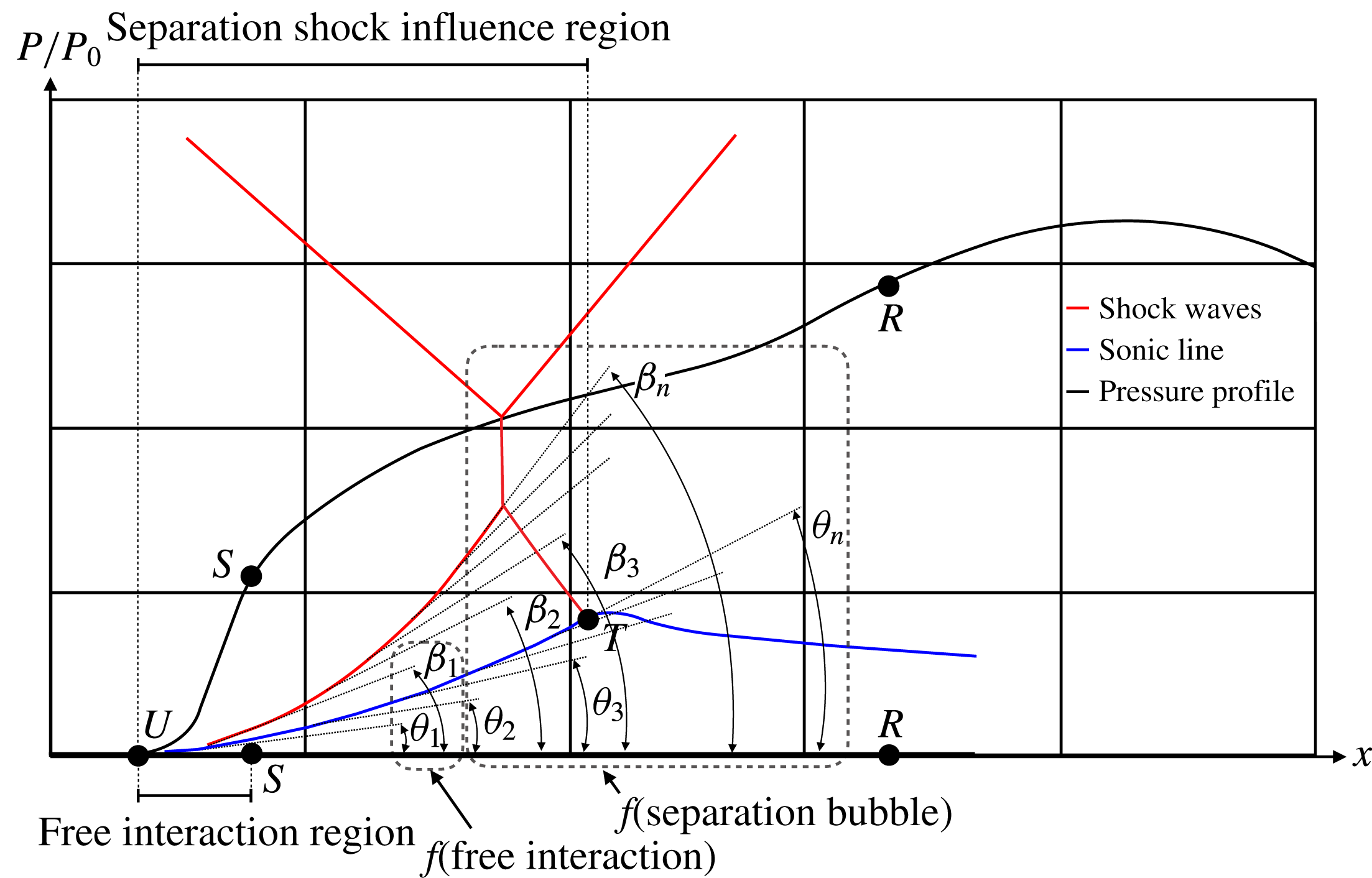
Figure 25. Extent to which free interaction theory affects separation shock development.
4 Conclusions
The results from a novel experimental set-up to vary the effective aspect ratio of a fixed aspect ratio wind tunnel were presented, demonstrating transition between an RR and an irregular reflected (MR) SWBLI without an increase in incident shock strength or flow deflection. Several shock generators of varying geometry, but all featuring a fixed flow deflection angle of
![]() $12^{\circ }$
, were tested in an
$12^{\circ }$
, were tested in an
![]() $M_{0}=2$
flow at a range of effective aspect ratios (
$M_{0}=2$
flow at a range of effective aspect ratios (
![]() $AR_{eff}=1.00$
–
$AR_{eff}=1.00$
–
![]() $1.38$
). Features of the resulting SWBLI were visualised and quantified through the use of schlieren photography, PIV, surface oil flow visualisation and high-spatial-resolution static pressure measurements.
$1.38$
). Features of the resulting SWBLI were visualised and quantified through the use of schlieren photography, PIV, surface oil flow visualisation and high-spatial-resolution static pressure measurements.
In § 3.1, it was observed through schlieren photography that an increase in
![]() $AR_{eff}$
from 1.00 to 1.38 resulted in an SWBLI evolution from an Edney type I interference (RR-SWBLI) to an Edney type II interference (MR-SWBLI), with an associated onset of MR. This evolution was confirmed in a time-averaged sense in § 3.3 through the use of PIV, which also made it possible to measure the average separation shock angles and to produce shock polars for the two states. Surface flow visualisations revealed the critical point topology of the separated flow regions, giving insight into the three-dimensionality of the flow. An increase in the streamwise extent of the shock-induced boundary layer separation was observed with an increase in
$AR_{eff}$
from 1.00 to 1.38 resulted in an SWBLI evolution from an Edney type I interference (RR-SWBLI) to an Edney type II interference (MR-SWBLI), with an associated onset of MR. This evolution was confirmed in a time-averaged sense in § 3.3 through the use of PIV, which also made it possible to measure the average separation shock angles and to produce shock polars for the two states. Surface flow visualisations revealed the critical point topology of the separated flow regions, giving insight into the three-dimensionality of the flow. An increase in the streamwise extent of the shock-induced boundary layer separation was observed with an increase in
![]() $AR_{eff}$
. It was also seen that the arrangement of the critical point topology changes with an increase in
$AR_{eff}$
. It was also seen that the arrangement of the critical point topology changes with an increase in
![]() $AR_{eff}$
. This change in critical point topology in turn sees the streamwise separation lengths grow proportionally with
$AR_{eff}$
. This change in critical point topology in turn sees the streamwise separation lengths grow proportionally with
![]() $AR_{eff}$
.
$AR_{eff}$
.
The transition from RR-SWBLI to MR-SWBLI with an increase in
![]() $AR_{eff}$
and a fixed flow deflection angle raised two questions. The first concerns the role of the downstream expansion fan and the upstream propagation of information due to the fact that increasing
$AR_{eff}$
and a fixed flow deflection angle raised two questions. The first concerns the role of the downstream expansion fan and the upstream propagation of information due to the fact that increasing
![]() $AR_{eff}$
alters the relative orientation of the SWBLI and the expansion fan. Second, it was observed in the study of Matheis & Hickel (Reference Matheis and Hickel2015) that the time-averaged separation shock angle was constant for flow deflections
$AR_{eff}$
alters the relative orientation of the SWBLI and the expansion fan. Second, it was observed in the study of Matheis & Hickel (Reference Matheis and Hickel2015) that the time-averaged separation shock angle was constant for flow deflections
![]() $\unicode[STIX]{x1D703}>11^{\circ }$
in an
$\unicode[STIX]{x1D703}>11^{\circ }$
in an
![]() $M_{0}=2$
flow. Furthermore, it was concluded by Matheis & Hickel (Reference Matheis and Hickel2015) that this was characteristic of the free interaction theory of Chapman et al. (Reference Chapman, Kuehn and Larson1958), which, if applicable, would seemingly prohibit any transition from RR-SWBLI to MR-SWBLI with a fixed flow deflection.
$M_{0}=2$
flow. Furthermore, it was concluded by Matheis & Hickel (Reference Matheis and Hickel2015) that this was characteristic of the free interaction theory of Chapman et al. (Reference Chapman, Kuehn and Larson1958), which, if applicable, would seemingly prohibit any transition from RR-SWBLI to MR-SWBLI with a fixed flow deflection.
In § 3.4, the role of the expansion fan was investigated in detail through the use of additional shock generators. Each shock generator featured a different thickness or corner rounding which respectively physically or virtually shifted the sharp corner of the shock generator, enabling a systematic investigation of their effects. It was observed that with a downstream movement of the expansion fan, SWBLI size, triple point height, separation size, separation length and static pressure distribution all grew. The relationship between
![]() $AR_{eff}$
and expansion fan placement was further investigated in § 3.5. It was observed that the centreline separation length grew linearly with an increase in separation between the SWBLI and the expansion fan, and that the growth in the separated region was accommodated primarily by an upstream movement of the separation point, with the reattachment point remaining almost fixed for
$AR_{eff}$
and expansion fan placement was further investigated in § 3.5. It was observed that the centreline separation length grew linearly with an increase in separation between the SWBLI and the expansion fan, and that the growth in the separated region was accommodated primarily by an upstream movement of the separation point, with the reattachment point remaining almost fixed for
![]() $AR_{eff}=1.00$
–
$AR_{eff}=1.00$
–
![]() $1.35$
. Furthermore, no independence of the SWBLI from the placement of the expansion fan was observed for the entire range of placements achievable in this experiment. This conclusion raises important questions about the influence of such ‘secondary’ geometric features of an experimental set-up, which, more often than not, are not fully considered or go completely unreported. Further investigation through experiments with test cases that provide a greater achievable range of expansion fan placement, which could only be accomplished with shock generators featuring lower flow deflection angles and/or tests at higher Mach numbers, may help to better understand the upstream expansion fan influence on SWBLIs.
$1.35$
. Furthermore, no independence of the SWBLI from the placement of the expansion fan was observed for the entire range of placements achievable in this experiment. This conclusion raises important questions about the influence of such ‘secondary’ geometric features of an experimental set-up, which, more often than not, are not fully considered or go completely unreported. Further investigation through experiments with test cases that provide a greater achievable range of expansion fan placement, which could only be accomplished with shock generators featuring lower flow deflection angles and/or tests at higher Mach numbers, may help to better understand the upstream expansion fan influence on SWBLIs.
In § 3.6, the applicability of free interaction theory with respect to the pressure rise to separation was observed. However, due to the relative weakness of the interaction, no pressure profile plateau was observed in any of the test cases. In light of this, an SWBLI representation was presented and reasoned in § 3.7, which explained the observed results, suggesting that for the weak interaction observed in this study, free interaction theory, while contributing to the definition of the mean separation shock angle, does not prohibit the vast majority of the mean separation shock from being influenced by the separation bubble as a whole, including any downstream factors.
Acknowledgements
The first author gratefully acknowledges the support of the Imperial College President’s PhD Scholarship Scheme, supported by the EPSRC, for funding this research.


