1 Introduction
High-power narrow-linewidth fiber lasers with excellent beam quality have been highly desired for spectral and coherent beam combinations[Reference Shi, Fang, Zhu, Norwood and Peyghambarian1-Reference Liu, Ma, Su, Tao, Ma, Wang and Zhou3]. The power scaling of single-mode narrow-linewidth fiber lasers has been under intense investigation[Reference Flores, Robin, Lanari and Dajani4-Reference Lin, Tao, Li, Wang, Guo, Shu, Zhao, Xu, Wang, Jing and Chu15]. This mainly involves comprehensive suppressions of the transverse mode instabilities (TMIs) and nonlinear inelastic scattering effects, such as stimulated Brillouin scattering (SBS) and stimulated Raman scattering (SRS)[Reference Dawson, Messerly, Beach, Shverdin, Stappaerts, Sridharan, Pax, Heebner, Siders and Barty16-Reference Zervas18]. Basic principles to increase the TMI and SBS/SRS thresholds in high-power fiber lasers have already been proposed based on the understanding of those effects[Reference Jauregui, Stihler and Limpert19-Reference Smith20]. Specifically, the TMI effect could be suppressed through reducing the strength of the thermally induced index grating, manipulating the phase shift between the thermally induced refractive index grating and the modal interference pattern, and decreasing the relative gain of the higher-order modes (HOMs)[Reference Jauregui, Stihler and Limpert19]. The SBS/SRS effects could be suppressed through reducing the effective fiber length or the effective Brillouin/Raman gain coefficient[Reference Smith20]. Those principles could be fulfilled mainly through special design of active fiber or optimization of the structure and parameters of fiber amplifiers. As for the fiber design, a near single-mode fiber laser with an output power of 3 kW and spectral linewidth of 12 GHz has been achieved based on gold-coated specialty gain fiber[Reference Yu, Shatrovoy, Fan and Taunay5], and a single-mode fiber laser with an output power of 3.5 kW and spectral linewidth of 0.18 nm has been achieved based on low-numerical aperture (NA) low-mode-area (LMA) gain fiber[Reference Beier, Hupel, Kuhn, Hein, Nold, Proske, Sattler, Liem, Jauregui, Limpert, Haarlammert, Schreiber, Eberhardt and Tunnermann6]. It should be noted that those two fiber laser systems are established in free-space structure, which is not suitable for compact assembling and maintenance. Therefore, most of the reported all-fiberized narrow-linewidth fiber amplifiers are based on conventional active fiber and require comprehensive optimization of structure and parameters of the fiber amplifiers[Reference Jiang, Ma, Huang, Xu, Zhou and Gu7-Reference Lin, Tao, Li, Wang, Guo, Shu, Zhao, Xu, Wang, Jing and Chu15]. As for all-fiberized format, 3.7-kW output power has been achieved with near-diffraction-limited beam quality and spectral linewidth of approximately 0.3 nm[Reference Lin, Tao, Li, Wang, Guo, Shu, Zhao, Xu, Wang, Jing and Chu15].
There exist certain internal contradictions between the design strategies to suppress the TMI effect and the nonlinear effects. For example, weakening heat load along the fiber could increase the TMI threshold, whereas the longer active fiber required in this case would decrease the SBS and SRS thresholds. Increasing the core diameter could increase the SBS and SRS thresholds whereas it would introduce more HOMs and increase the risk of the TMI effect. Furthermore, the TMI effect and the nonlinear effects are interrelated in high-power fiber lasers[Reference Hejaz, Shayganmanesh, Rezaei-Nasirabad, Roohforouz, Azizi, Abedinajafi and Vatani21-Reference Distler, Möller, Strecker, Palma-Vega, Walbaum and Schreiber24]. Therefore, further power scaling of high-power fiber lasers would face the interplay of the multiple restrictions, which requires new understanding in the fiber material and structural design or the comprehensive optimization of the amplification configuration. The pumping configuration is an important design parameter which could influence both the TMI and the SBS/SRS thresholds. As for the SBS/SRS effect, the counter-pumped configuration is the most favorable, because the high-power signal only propagates over a relatively short length of the fiber (at the end of the fiber), which reduces the effective fiber length of high-power fiber lasers[Reference Wang25]. As for the TMI effect, most of the theoretical studies coincide in pointing out that the bidirectional configuration might offer some advantage over the sole forward-pumped or backward-pumped case[Reference Jauregui, Stihler and Limpert19, Reference Smith and Smith26-Reference Tao, Ma, Wang, Zhou and Liu28].
In this work, an all-fiberized and narrow-linewidth 5-kW power-level fiber laser has been demonstrated based on a bidirectional pumping configuration, in which the power ratio of the copropagating and counterpropagating pump lasers is selected to be about 1:3. The 3-dB spectral width is about 0.59 nm, and the beam quality is M 2 = 1.22 at maximum output power of about 4.92 kW. In addition, the detailed spectral evolution of the signal laser is measured and analyzed in this paper. The experimental system design strategies and results could provide instructive guidance for achieving high-brightness narrow-linewidth fiber lasers with high spectral purity.
2 Experimental setup
The experimental setup of the high-power all-fiberized and narrow-linewidth amplifier based on a master oscillator power amplification (MOPA) configuration is illustrated in Figure 1. The initial laser is a linearly polarized low-noise single-frequency laser (SF seed) with central wavelength of approximately 1071 nm and output power of about 20 mW[Reference Zhao, Xu, Zhou, Yang, Li, Feng, Peng, Deng and Yang29]. The initial laser is externally modulated through a fiber-coupled LiNbO3 electro-optic modulator (EOM), driven by a white noise signal (WNS) generator and a radiofrequency (RF) amplifier, to broaden its spectral width for SBS suppression. The output power of the seed laser after phase modulation is about 10 mW. The laser power is then preamplified by using three stages of preamplifiers. The first two preamplifiers are commercial Yb-doped preamplifiers and the output power could be boosted to about 5 W after the two amplification processes. The third preamplifier is a cladding-pumped Yb-doped fiber amplifier. A pair of laser diodes (LDs) with maximal total output power of 100 W and central wavelength of 976 nm is used to pump 4.5-m-long active fiber (YDF 1) via a (2+1)×1 pump combiner. The core and cladding diameters of the active fiber are 10 and 125 μm, respectively. The output power is scaled to about 30-W power level after the isolator (IOS) in the third preamplifier. A band-pass filter (BPF) is applied to filter out part of the background spectral noise in the preamplified laser. To monitor the backward power from the main amplifier, a fiber tap coupler is applied here, and the coupling ratios of the backward monitor port and injected signal port are 0.1% and 99.9%, respectively.
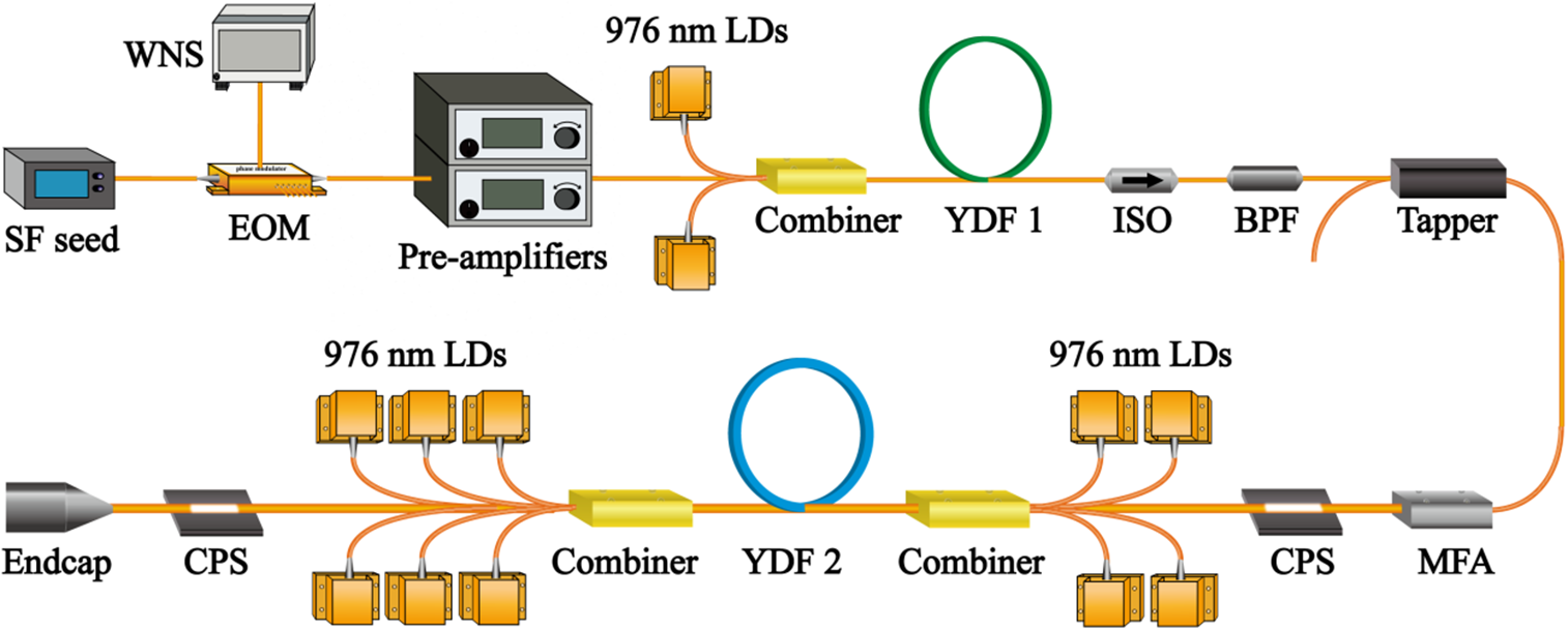
Figure 1 Experimental setup of the high-power narrow-linewidth fiber laser system.
A mode field adaptor (MFA) is utilized to improve the coupling between the preamplifier and the main amplifier. The main amplifier consists of an Yb-doped fiber (YDF 2), two signal–pump combiners, two cladding pump strippers (CPSs), and a quartz beam hat (QBH). The active fiber is a commercially available fiber with core and inner cladding diameters of approximately 20 and 400 μm, respectively. The NA values of core and inner cladding are about 0.062 and 0.46, respectively. The cladding absorption coefficient of the active fiber is about 1.2 dB/m at 976 nm, and 16 m active fiber is used in the main amplifier. To balance the TMI suppressing effect and the reliability, the active fiber was coiled with a diameter of approximately 10.5 cm to increase the relative loss of HOMs in the final amplifier. The cooling configuration of the active fiber is based on our proprietary technique described in Ref. [Reference Su, Wang, Zhou, Tao, Ma, Zhang, Si, Xu, Chen and Liu30]. About 3 m double-clad passive fiber is spliced to the active fiber for power delivery. The CPSs are utilized to remove unwanted cladding light and the endcap is utilized to deliver the output laser into free space. The high-power laser diodes (LDs) emitting at a stabilized wavelength of 976 nm are divided into two groups to realize forward-pumped and backward-pumped configurations, respectively.
3 Experimental design strategies
As pointed out previously, balancing and suppressing the SBS, SRS, and TMI effects is the significant focus point for power scaling of narrow-linewidth fiber amplifiers. As for the MOPA configuration, the experimental design strategies mainly refer to the injected seed laser, pumping wavelength, active fiber, and the forward/backward pumping power ratios. In general, the characteristics of injected seed mainly affect the SBS, SRS, and TMI effects in the power amplification process[Reference Jauregui, Stihler and Limpert19, Reference Liu, Ma, Lv, Xu, Zhou and Jiang31–Reference Ma, Miao, Liu, Meng and Zhou33]. As for SBS effect, employing the broadening narrow-linewidth seed injection is the prevailing technique, in which the Brillouin gain spectrum could be appropriately broadened to enhance the SBS threshold. Nowadays, the filtered super-fluorescent source[Reference Zheng, Yang, Wang, Hu, Liu, Zhao, Chen, Liu, Zhao, He and Zhou2], multi-longitudinal-mode fiber oscillator[Reference Jiang, Ma, Huang, Xu, Zhou and Gu7-Reference Shen, Lou, Quan, Li, Yang, Chen, Li, Bai, Qi, He and Zhou9], random fiber laser[Reference Xu, Huang, Jiang, Ye, Ma, Leng, Wu, Zhang and Zhou10], fiber-Bragg-grating-stabilized laser diode[Reference Lee, Lee, Jeong, Park, Seung and Lee11], and phase-modulated single-frequency laser[Reference Flores, Robin, Lanari and Dajani4, Reference Yu, Shatrovoy, Fan and Taunay5, Reference Li, Zha, Sun, Ma, Ke and Peng12-Reference Lin, Tao, Li, Wang, Guo, Shu, Zhao, Xu, Wang, Jing and Chu15] have been used as the narrow-linewidth injected seed in high-power MOPA configurations. Among these different types, phase-modulated single-frequency laser has been proved to be preferable for the reason of stable temporal property, high SRS threshold, and spectral purity during the amplification process[Reference Liu, Ma, Lv, Xu, Zhou and Jiang31-Reference Ma, Miao, Liu, Meng and Zhou33]. In addition, stable temporal property and low-intensity noise are also compatible with the TMI-suppressing requirement of injected seed laser[Reference Jauregui, Stihler and Limpert19]. That is why a phase-modulated single-frequency laser is employed in our experiment. Notably that fiber amplifier with subnanometer spectral width had been validated to be feasible for high-power spectral beam combining systems by designing the beam diameters[2] and it could also be used in high-power coherent beam combining systems with active optical mismatch compensating[Reference Liu, Ma, Su, Tao, Ma, Wang and Zhou3]. As for pumping wavelength selection, wavelength-stabilized LDs with 976 nm central wavelength are selected to pump the main fiber amplifier for decreasing the quantum loss and ensuring high optical-to-optical conversion efficiency. In addition, the Yb3+ ion has the highest absorption coefficient at this wavelength so that the effective length of active fiber could be decreased, which is beneficial for SBS and SRS suppression. However, it should be noted that the TMI threshold is lowest at this pumping wavelength[Reference Tao, Ma, Wang, Zhou and Liu34]. Thus, in terms of the active fiber selection, TMI suppression is the preferable aspect for balancing different detrimental factors. According to our previous study[Reference Tao, Su, Ma, Wang and Zhou35], the passive coiling technique along with decreasing fiber core diameter will be more efficient on increasing the TMI threshold. Accordingly, comprehensively considering the power extracting ability, the conventional active fiber with core/inner-cladding diameters of approximately 20/400 μm is employed in this experiment. Thus, the TMI effect is generated from the interaction between fundamental mode and HOMs, increasing the relative loss of HOMs is an effective method for increasing TMI threshold[Reference Jauregui, Stihler and Limpert19]. Among different HOM loss management approaches, coiling active fiber is a simple and economical technique because the active fiber will not be modified. In our experiment, the active fiber is coiled with an equivalent diameter of about 10.5 cm for further TMI suppression. Notably that smaller coiling diameter will be more beneficial for TMI suppression whereas the thermal management pressure would increase in a high-power situation. In the following analysis, we show that this coiling diameter is sufficient for 5-kW power-level scaling by optimizing the pump power distribution.
In general, the SBS and SRS thresholds are compatible for different pump power distributions, which will increase along with the backward-pumped power ratio[Reference Wang25]. However, in a specific fiber laser system, an optimal backward-pumped power ratio exists for suppressing the TMI effect[Reference Tao, Ma, Wang, Zhou and Liu28]. Further, by selecting the proper phase-modulation depth and electronic bandwidth of the modulation signal, the spectral width could be broadened to suppress SBS sufficiently. Thus, the following analysis is mainly focused on balancing the SRS and TMI effects by optimizing the pump power distribution. Figure 2 shows the SRS and TMI threshold evolution along with the backward-pumped power ratio. Here the SRS and TMI thresholds are respectively calculated by the spectral model and the semi-analytical model developed by our group[Reference Liu, Ma, Lv, Xu, Zhou and Jiang31, Reference Tao, Su, Ma, Wang and Zhou35]. The major simulation parameters of the fiber amplifier, including the coiling diameter, signal and pump wavelengths, pump absorption coefficient, core NA, lengths of the active and passive fibers, and diameters of core and inner cladding, are all based on the experimental setup shown in the Section 2. In Figure 2, the SRS threshold is defined as the output power when the power ratio of the Raman Stokes light reaches 0.1%, and the TMI threshold is defined as the output power when the power ratio of the LP11 HOM increases from 1% to 10% in total output power. From Figure 2, it is shown that the acceptable backward pump ratio is located within about 85%±10% for achieving 5-kW-level output power. Further considering the power-handing ability of backward signal–pump combiner, the forward- and backward-pumped power ratio is set to be around 1:3 in the experiment.
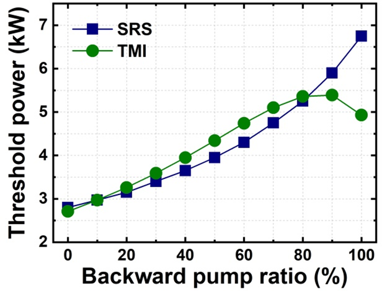
Figure 2 SRS and TMI threshold evolution along with the backward-pumped power ratio.
4 Experimental results and discussion
The SBS effect in the main amplifier is suppressed mainly through the phase modulation for the SF seed. To ensure sufficient enhancement of the SBS threshold, a filtered WNS with electronic bandwidth of 12 GHz and RF power of 0.26 W is applied to the EOM for phase modulation and spectral broadening. The 3-dB spectral width of the SF seed after phase modulation is set to be about 0.6 nm. Figure 3 illustrates the spectrum of the seed laser inserted into the main amplifier. The spectrum of the signal laser is measured through a commercial optical spectral analyzer (OSA) with the spectral resolution of 0.02 nm here and in the following experiments. As shown in Figure 3, the spectral shape of the seed laser is close to Gaussian and the 3-, 20-, and 30-dB spectral widths are about 0.64, 1.39, and 1.68 nm, respectively.
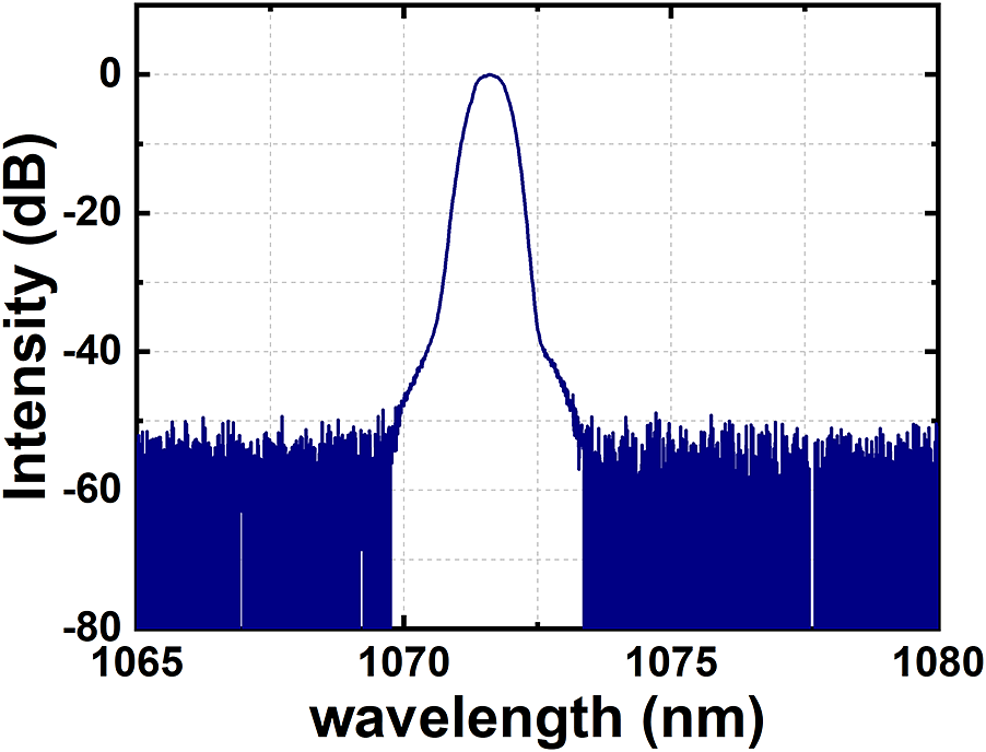
Figure 3 Spectrum of the seed laser.
The co-propagating and counter-propagating pump lasers are injected ordinally in the main amplifier. Specifically, we first increase the co-propagating pump laser to about 1.49 kW, and then increase the counter-propagating pump laser to about 4.66 kW. Figure 4 illustrates the output powers of the signal laser and backward propagating laser at different pump power in the main amplifier. As shown in Figure 4, the output power of the signal laser increases almost linearly with the pump power. At the maximum pump power of about 6.15 kW, the output power of the signal laser is about 4.92 kW and the corresponding slope efficiency is about 80%. Meanwhile, the output power of the backward-propagating laser grows gradually from 1 mW to about 0.42 W at the maximum pump power, and there is no sign of nonlinear increase for the output power of backward propagating laser. Thus, the SBS effect is effectively suppressed in this main amplifier at the maximum output power.
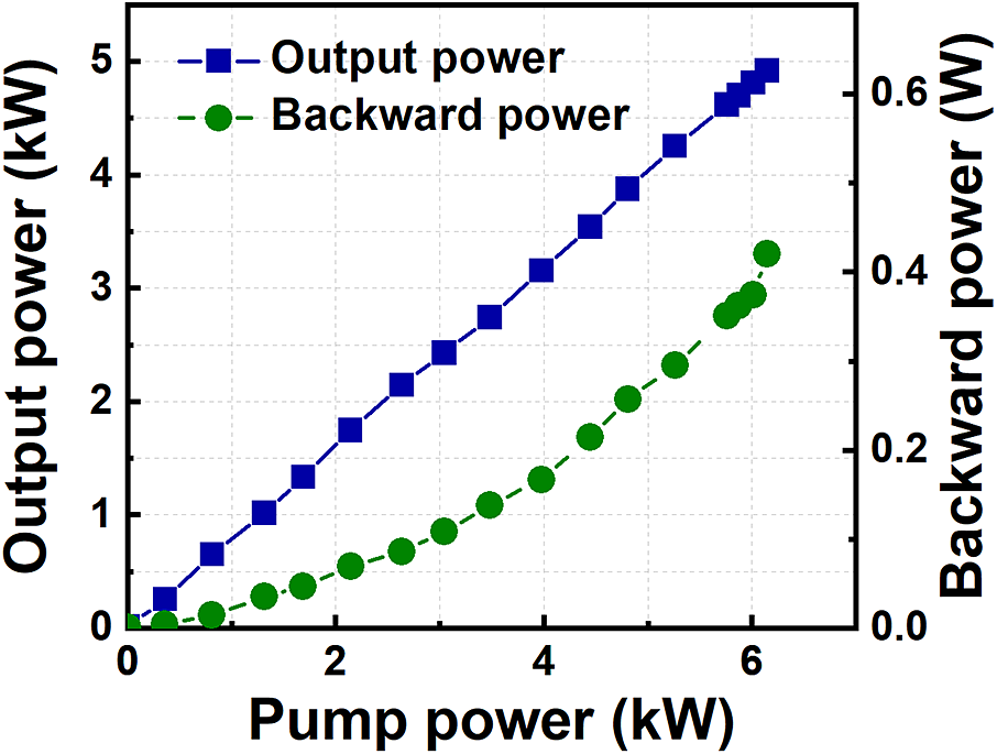
Figure 4 Output powers of the signal laser and backward-propagating laser at different pump power.
Apart from the output power, the output spectral property, especially for the spectral purity, is one of the key parameters that determine the performance of high-power narrow-linewidth fiber lasers. Thus, the spectral evolution of the signal laser is measured and analyzed in detail. Figure 5 illustrates the output spectra of the signal laser at different output power in the main amplifier. As shown in Figure 5, the central spectra of the signal laser remain almost unchanged, whereas there exists an obvious spectral wing broadening phenomenon with increasing output power. In addition, the spectral component near the 1125 nm begins to increase at an output power of about 3.94 kW. The peak signal-to-noise ratio is about 43 dB compared with the Raman Stokes light at the maximum output power.

Figure 5 Output spectra of the signal laser at different output power in the main amplifier.
To give a more quantitative description of this spectral wing broadening effect, we have calculated the spectral width of the signal laser in the logarithmic coordinates and power-ratio spectral width at different output power. Here, the power-ratio spectral width is defined as the minimum spectral width within which the power ratio of the signal laser is over a certain proportion. Figure 6 illustrates the spectral widths of the signal laser at different output powers. As shown in Figure 6(a), the 3-dB spectral width of the signal laser remains around 0.6 nm at different output power, and becomes about 0.59 nm at the maximum output power, which is a little narrower than that of the inserted seed laser (0.64 nm). For the 20-dB spectral width, it grows gradually from 1.39 nm to about 2.78 nm at the maximum output power. For the 30-dB spectral width, it grows steadily from 1.68 nm to about 2.98 nm when the output power is below 4.08 kW, and grows quickly to about 5.14 nm at the maximum output power. As shown in Figure 6(b), the 80% power-ratio spectral width grows gradually from about 0.63 nm to about 0.85 nm, and the 90% power-ratio spectral width grows gradually from about 0.79 nm to about 1.24 nm, at the maximum output power. As for the 99% power-ratio spectral width, it grows steadily from 1.18 nm to about 1.83 nm when the output power is below 4.08 kW, and grows quickly to about 3.17 nm at the maximum output power. The steep increase in the 30-dB spectral width or the 99% power-ratio spectral width of the signal laser corresponds to the obvious spectral wing broadening phenomenon and the decrease of the spectral purity, especially in high-power operation. In a high-power narrow-linewidth fiber amplifier, apart from the narrow band phase-modulated single-frequency part, the broadband background spectral noise, which originates from the seed laser or the spontaneous emission noise in the amplifier stage, could also be amplified during power scaling. Furthermore, our recent theoretical analysis revealed that the four-wave-mixing (FWM) effect could lead to obvious energy conversion from the phase-modulated single-frequency part into the background spectral noise during the power scaling process[Reference Liu, Song, Ma, Xiao and Zhou36]. Consequently, both the amplification process and nonlinear FWM effect contribute to the enhancement of background spectral noise, and the broadband background spectral noise gets extra amplification compared with the central phase-modulated single-frequency part, which finally leads to the obvious spectral wing broadening phenomenon in the narrow-linewidth fiber amplifiers.

Figure 6 Spectral width of the signal laser at different output power: (a) spectral width in the logarithmic coordinates; (b) power-ratio spectral width.
The corresponding power ratio of the Raman Stokes light (called as the Raman ratio for short) could also be estimated through the measured spectra. Figure 7 illustrates the Raman ratio in the total output laser at different output power. Here, the Raman ratio is calculated through dividing integrated spectrum from 1100 to 1150 nm by integrated spectrum from 1000 to 1150 nm. As shown in Figure 7, the Raman ratio remains around –46.5 dB (0.002%) when the output power is below 3.67 kW, and grows quickly to about –32.6 dB (0.055%) at the maximum output power. Therefore, despite the fact that the SRS effect is effectively suppressed at the maximum output power, further power scaling of this narrow-linewidth fiber laser could still be restricted by the SRS effect.

Figure 7 Power ratio of the Raman Stokes light at different output power.
The intensity evolution of the signal laser and the corresponding power spectral density at the maximum output power are measured by using an oscilloscope with 1-GHz bandwidth and a photo-detector (PD) with 150-MHz electro-optic bandwidth. Figures 8(a) and 8(b) illustrate the normalized intensity evolution and the corresponding power spectral density of the signal laser at the maximum output power. As shown in Figure 8(a), the normalized intensity evolution of the signal laser remains relatively stable in millisecond time scale and the corresponding standard deviation is only about 1.15%. As shown in Figure 8(b), the corresponding power spectral density remains relatively flat in the frequency range from 0.1 to 20 kHz, and there is no sign of typical frequency peaks or envelopes, which indicates that this fiber amplifier works well below the TMI threshold at the maximum output power. The beam quality of the signal laser is measured by the laser quality monitor. As shown in Figure 8(c), the beam quality at the maximum output power is measured as M 2 = 1.22.
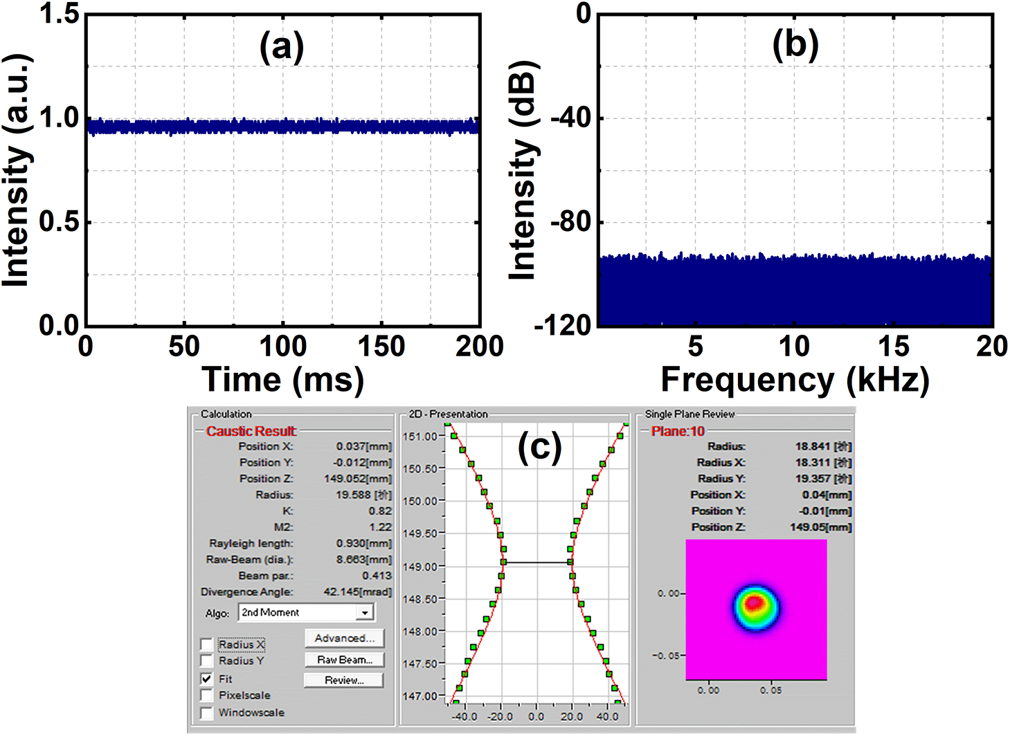
Figure 8 Output temporal property and beam quality of the signal laser at the maximum output power: (a) normalized intensity evolution; (b) corresponding power spectral density; (c) beam quality.
5 Conclusion
In summary, we have presented an all-fiberized narrow-linewidth fiber amplifier with record output power of 5-kW level based on bidirectional pumping configuration in the MOPA configuration. We have achieved a 4.92-kW fiber laser with the 3-dB spectral width of about 0.59 nm, beam quality of M 2 = 1.22, and slope efficiency of about 80%. The SBS, SRS, and TMI effects are effectively suppressed in the experiment at the maximum output power. The spectral analysis of signal laser clarifies the property of the spectral wing broadening phenomenon and the growth of the Raman Stokes light in this narrow-linewidth fiber amplifier, which indicates that further improvement of the laser performance, i.e., the spectral purity and the power scalability, could be restricted by the spectral wing broadening phenomenon and the SRS effect, respectively. Overall, this work could provide a reference for obtaining and optimizing high-power narrow-linewidth fiber lasers with high spectral purity.
Acknowledgments
This work was supported by the Guangdong Key Research and Development Program (No. 2018B090904001), the National Natural Science Foundations of China (Nos. 62005313 and 61705264), the Innovative Research Team in Natural Science Foundation of Hunan Province (No. 2019JJ10005), and the Hunan Provincial Innovation Construct Project (No. 2019RS3017). We thank Associate Prof. Zilun Chen for developing the endcap and CPS used in the experiment. We also thank Liang Xiao, Jiawei He, Tao Song, Xiangrong Yu, Xiaoyong Xu, and Kun Zhang for their help in experimental operations.


