Hostname: page-component-7bb8b95d7b-fmk2r Total loading time: 0 Render date: 2024-09-29T17:03:22.279Z Has data issue: false hasContentIssue false

A theory on leading-edge vortex stabilization by spanwise flow

Published online by Cambridge University Press:  30 August 2023
Xi Xia*
Affiliation:
School of Mechanical Engineering, Shanghai Jiao Tong University, Shanghai 200240, PR China
Kamran Mohseni
Affiliation:
Department of Mechanical and Aerospace Engineering, University of Florida, Gainesville, FL 32611-6250, USA
*
Email address for correspondence: [email protected]

Abstract

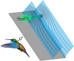
Natural flyers are capable of producing excessive lift via a stabilized leading-edge vortex (LEV), which appears to linger above the wing for a longer duration than it could in an equivalent two-dimensional flow. Previous studies found this stabilization behaviour closely related to a spanwise flow along the LEV axis; however, it is still debatable how the spanwise flow influences the LEV stability. In this work, potential flow theory is adopted to model an LEV attached to a flat-plate wing. To account for the spanwise flow effect, we propose a finite-area sink (FAS) model which allows the dynamical interaction between co-located LEV and spanwise flow. Through linear stability analysis of the dynamical system associated with the LEV movement, we arrive at a stable spiral-sink type of equilibrium, which is the first mathematical evidence supporting LEV stabilization by spanwise flow. It is further concluded that the LEV stability can be enhanced by either increasing the strength or decreasing the cross-section area of the spanwise flow.

Type
JFM Rapids
Copyright
© Shanghai Jiao Tong University, 2023. Published by Cambridge University Press

1. Introduction

Over the past decades, a core attraction in unsteady aerodynamics lies in the leading-edge vortex (LEV), which is key to the high lift performance and manoeuvrability of natural flyers. It was found that a major lift production occurs during the translational phase of wing downstroke (Ellington et al. Reference Ellington, van der Berg, Willmott and Thomas1996; Dickinson, Lehmann & Sane Reference Dickinson, Lehmann and Sane1999), when the flow is relatively steady and the LEV grows extensively. The enhanced lift has been attributed to LEV stabilization as the LEV of natural flyers appears to be more stable than that in an equivalent two-dimensional (2-D) flow, meaning it lingers for a longer duration and gains a larger circulation during the downstroke, resulting in delayed shedding and stall (Maxworthy Reference Maxworthy1981; Ellington Reference Ellington1984; DeVoria & Mohseni Reference DeVoria and Mohseni2017; Linehan & Mohseni Reference Linehan and Mohseni2020).

To explain LEV stabilization and trapping, Maxworthy (Reference Maxworthy1979) was the first to propose that a spanwise flow along the vortex axis pumps vorticity from the vortex core to the wing tip, thereby preventing the excessive growth of circulation and the subsequent vortex shedding. The existence of the spanwise flow pertaining to the LEV has been confirmed experimentally (Ellington et al. Reference Ellington, van der Berg, Willmott and Thomas1996; van den Berg & Ellington Reference van den Berg and Ellington1997), while its stabilizing effect on LEV has been corroborated by later studies (Liu et al. Reference Liu, Ellington, Kawachi, van den Berg and Willmott1998; Birch, Dickinson & Dickinson Reference Birch, Dickinson and Dickinson2004; Swanton, Vanier & Mohseni Reference Swanton, Vanier and Mohseni2010; Jardin & David Reference Jardin and David2014). The formation of spanwise flow in an LEV has been attributed to different factors including centrifugal acceleration, Coriolis force, wing aspect ratio and even bird alula (Lentink & Dickinson Reference Lentink and Dickinson2009; Beem, Rival & Triantafyllou Reference Beem, Rival and Triantafyllou2012; Carr, Chen & Ringuette Reference Carr, Chen and Ringuette2013; Garmann & Visbal Reference Garmann and Visbal2014; Jardin Reference Jardin2017; Linehan & Mohseni Reference Linehan and Mohseni2020).

Despite the rich phenomenological observations, which have provided irrefutable evidences supporting the correlation between spanwise flow and LEV stability, the underlying stabilization mechanism is still open to debate. As reviewed by Eldredge & Jones (Reference Eldredge and Jones2019), recent efforts were focused on vorticity transportation in verifying the effect of spanwise flow in discharging vorticity and maintaining a relatively constant LEV circulation. However, the results suggest that the balancing of vorticity transportation is the outcome of the combined effect of convection, stretching, Coriolis tilting and annihilation. To date, less attention has been given to the dynamical aspect of LEV stability – the persistent attachment which means a stagnation in vortex convection and shedding. Actually, relevant theoretical attempts have already been made in the past. Saffman & Sheffield (Reference Saffman and Sheffield1977) modelled the LEV as a free point vortex in 2-D and showed that the loci for LEV equilibrium are naturally unstable for most conditions. Rossow (Reference Rossow1978) further added a point sink co-locating with the point vortex to account for the bleeding effect of the spanwise flow in the LEV, but still failed to identify any stable equilibrium locus.

In this study, based on Rossow (Reference Rossow1978) coupled vortex-sink model, we propose to decouple the spanwise flow from the LEV because essentially they are formed by different mechanisms. Furthermore, we employ a finite-area sink (FAS) to model the spanwise flow not only because it better represents the reality, but more importantly for it offers a desingularized velocity field within the sink, thereby allowing the dynamical interaction between the vortex and the sink. Applying a linear stability analysis of the dynamical system associated with the LEV convection, we show for the first time that the spanwise flow modelled by a FAS could indeed promote LEV stabilization.

2. Mathematical formulation

2.1. Potential flow model

In the spirit of Rossow (Reference Rossow1978) potential flow model, we employ a point vortex to emulate the dynamical effect of an LEV, with a sink representing the spanwise flow. Potential flow has been proven effective in 2-D aerodynamic modelling of a flat plate or an airfoil, even for unsteady cases (Xia & Mohseni Reference Xia and Mohseni2013Reference Xia and Mohseni2017) as long as the viscous effects on vortex formation and shedding are properly resolved. For simplicity, we also make the assumption of ‘quasi-steady’ , which requires the main parameters, including background flow velocity, LEV circulation and spanwise flow strength, being invariant of time. This is justifiable for a stabilized LEV, for which both vortex circulation and spanwise flow velocity approach saturation (Jardin & David Reference Jardin and David2014).

In this set-up, we can formulate a simple model in the lab coordinate, denoted $z$-plane ($z = x + {\rm i}y$), where an LEV hovers over a 2-D flat plate undergoing a steady translational motion of speed $U$ at an angle of attack $\alpha$. The LEV is represented by a point vortex of circulation $\varGamma$ ($\varGamma < 0$) at $z_{\varGamma }$, with the spanwise flow modelled by a co-locating point sink of strength $Q$ ($Q > 0$). As illustrated in figure 1(a), the physical flow can be mapped out to the flow around a cylinder in the $\zeta$-plane ($\zeta = \xi + {\rm i}\eta$) using the Joukowski transformation:

(2.1)\begin{equation} z = \zeta + a^2\zeta^{-1} \quad \text{for } |\zeta| \geq a, \end{equation}

where $a$ is the radius of the cylinder; $a = c/4$ ($c$ is the chord length of the flat plate). Applying the circle theorem (Milne-Thomson Reference Milne-Thomson1958), the complex potential in the $\zeta$-plane can be explicitly written as

(2.2)\begin{align} w(\zeta) &= U (\zeta {\rm e}^{-{\rm i} \alpha}+ a^2\zeta^{-1} \, {\rm e}^{{\rm i} \alpha}) - \frac{{\rm i}\varGamma}{2{\rm \pi}}[\ln(\zeta - \zeta_{\varGamma}) - \ln (\zeta - a^2 {\bar{\zeta}_{\varGamma}}^{-1})]\nonumber\\ & \quad - \frac{{\rm i}\varGamma_B + {\rm i}\varGamma - Q}{2{\rm \pi}} \ln(\zeta) - \frac{Q}{2{\rm \pi}} [\ln(\zeta-\zeta_{\varGamma}) + \ln(\zeta-a^2 {\bar{\zeta}_{\varGamma}}^{-1})], \end{align}

where $\zeta _{\varGamma }$ is the LEV location in the $\zeta$-plane, and $\bar {}$ denotes the complex conjugate; $\varGamma _B$ is the bound circulation, which accounts for the effect of the entire viscous shear layers around the flat-plate surface and balances the effect of shed vortices in the far field. Given the quasi-steady assumption, $\varGamma _B$ can be calculated by implementing the steady-state Kutta condition at the trailing edge (Xia & Mohseni Reference Xia and Mohseni2013):

(2.3)\begin{equation} (\mathrm{d}w(\zeta)/\mathrm{d}\zeta)|_{\zeta=a} = 0. \end{equation}

Figure 1. Flow model and streamline for a 2-D flat plate with a quasi-steady LEV and spanwise flow. (a) Previous model: the spanwise flow is modelled by a point sink co-located with the LEV. (b) New model: the spanwise flow is modelled by a FAS placed independently from the LEV. The direction of the branch cut is determined in the $\zeta$-plane based on the polar angle of the image sink located at $a^2 {\bar {\zeta }_Q}^{-1}$, such that the multi-valuedness of the stream function contributed by the sink-source pair within the cylinder cancels each other.

By setting a stagnation point at $\zeta = a$ in the virtual $\zeta$-plane, (2.3) ensures a finite flow velocity near the trailing edge of the flat plate in the physical $z$-plane, thereby enforcing the streamline emanating from the trailing edge to be parallel to the plate and fulfilling the flow condition passing a sharp edge. The streamlines obtained by taking the imaginary component of (2.2) are plotted in figure 1(a). Note the line connecting the sink to the outside boundary is a branch cut (Ablowitz & Fokas Reference Ablowitz and Fokas2003), arising from the multi-valuedness associated with the stream function of the singular sink. Physically, the branch cut represents a discontinuity in the stream function, forming a zero-width passage to channel flow from the sink to the infinite far field. It can be interpreted as a corrective measure of the potential flow to restore the continuity violated by the sink singularity in a 2-D flow.

Based on this model, we analysed the LEV stability in a previous study (Xia & Mohseni Reference Xia and Mohseni2012) and found the LEV to be fundamentally unstable; this result, however, contradicts the consensus that spanwise flow is helpful for LEV stabilization. As an improvement, here we propose to replace the point sink with a FAS, where the total strength $Q$ is uniformly distributed within a finite area $S_0$. Furthermore, this new sink is placed at $z_Q$, which is decoupled from the vortex location $z_{\varGamma }$. These updates are intended to allow for the dynamical interaction between vortex and sink, especially when they overlap spatially. We believe that failure in capturing this effect previously was responsible for the prediction of an unstable LEV. In this model, we assume the FAS in the $\zeta$-plane has a circular shape $S$ of radius $r$ and is centred at $\zeta _Q$. Note that the mapped FAS in the $z$-plane is not strictly circular; however, under the small-area approximation requiring $r \ll a$, it approaches a circular area $S_0$, with radius $r_0$ satisfying $r/r_0 = |\zeta _Q^2/(\zeta _Q^2-a^2)|$. This theory does not require the small-area approximation since the potential flow is based on $r$ rather than $r_0$. Nevertheless, $r_0$ is still meaningful in ensuring an approximately constant sink area for the FAS in the physical plane. A sample flow with a decoupled LEV and FAS is illustrated in figure 1(b).

Following this conceptualization, the FAS is effectively an area integral of the sink element $Q \mathrm {d}A/({\rm \pi} r^2)$. Accordingly, (2.2) can be updated as

(2.4)\begin{align} w(\zeta) &= U (\zeta {\rm e}^{-{\rm i} \alpha}+ a^2\zeta^{-1} \, {\rm e}^{{\rm i} \alpha}) -\frac{{\rm i}\varGamma}{2{\rm \pi}}[ \ln(\zeta - \zeta_{\varGamma}) - \ln (\zeta - a^2 {\bar{\zeta}_{\varGamma}}^{-1})]\nonumber\\ &\quad - \frac{{\rm i}\varGamma_B + {\rm i}\varGamma - Q}{2{\rm \pi}} \ln(\zeta) - \frac{Q}{2{\rm \pi}^2 r^2} \iint_{S} [\ln(\zeta-\zeta_q) + \ln(\zeta-a^2 {\bar{\zeta}_q}^{-1})]\,\mathrm{d}A, \end{align}

where $\zeta _q$ is the $\zeta$-plane location of the sink element. For flow outside of the sink ($|\zeta -\zeta _Q| > r$), we can convert the area integral in (2.4) to contour integral using the identity

(2.5)\begin{equation} \iint_S \frac{\partial F}{\partial \zeta_q}\, \mathrm{d}A = \frac{{\rm i}}{2}\oint_{\partial S} F\, \mathrm{d}\bar{\zeta}_q, \end{equation}

the derivation of which involves the Wirtinger derivatives (Kracht & Kreyszig Reference Kracht and Kreyszig1988) and Green theory. Here, $F(\zeta _q)$ is analytic over the sink area $S$ (encircled by $\partial S$). Applying the Laurent series and residue theorem, the contour integral can be calculated as

(2.6)\begin{equation} \iint_{S} [ \ln(\zeta-\zeta_q) + \ln(\zeta-a^2 {\bar{\zeta}_q}^{-1})]\,\mathrm{d}A = {\rm \pi}r^2 [ \ln(\zeta-\zeta_Q) + \ln(\zeta-a^2 {\bar{\zeta}_Q}^{-1}) ], \end{equation}

which recovers the complex potential as if a point sink $Q$ were placed at $\zeta _Q$. Note (2.6) is valid only for flow outside the FAS ($|\zeta -\zeta _Q| > r$). Within the FAS ($|\zeta -\zeta _Q| \le r$), the complex potential (2.4) is singular, meaning the potential flow does not exist so that the FAS shows up as a blank area in the streamlines of figure 1(b). The above explains the presence of the branch cut extending from the FAS surface to infinity. By satisfying the trailing-edge Kutta condition (2.3), the bound circulation $\varGamma _B$ is calculated to be

(2.7)\begin{equation} \varGamma_{B} = 2 a \left[-2{\rm \pi} U \sin (\alpha ) + \frac{\varGamma(\xi_{\varGamma} - a)}{(\xi_{\varGamma} - a)^2+\eta_{\varGamma}^2} - \frac{Q\eta_Q}{(\xi_Q - a)^2+\eta_Q^2} \right], \end{equation}

where $\zeta _{\varGamma } = \xi _{\varGamma } + {\rm i}\eta _{\varGamma }$ and $\zeta _Q = \xi _Q + {\rm i}\eta _Q$.

2.2. LEV convection velocity

We next proceed to evaluate the LEV movement by calculating its convection velocity in the $z$-plane:

(2.8)\begin{equation} u_{\varGamma} - {\rm i}v_{\varGamma} = (\mathrm{d} w'(z)/\mathrm{d} z)|_{z=z_{\varGamma}}, \end{equation}

where $w'(z)$ is the complex potential of the desingularized background flow excluding any singularity at $z_{\varGamma }$. So $w'(z)$ is related to the original $w(z)$ as

(2.9)\begin{equation} w'(z) = w(z) + \frac{{\rm i}\varGamma}{2{\rm \pi}}\ln(z - z_{\varGamma}). \end{equation}

Within the FAS ($|\zeta -\zeta _Q| \le r$), the right-hand side of (2.9) has an additional singular term,

(2.10)\begin{equation} \frac{Q}{2{\rm \pi}^2r_0^2} \iint_{|z_q-z|<\epsilon,\epsilon \rightarrow 0} \ln(z - z_q) \,\mathrm{d}A', \end{equation}

which is estimated to be of order $O(\epsilon ^2 \ln (\epsilon )) \sim 0$ as $\epsilon \rightarrow 0$; $z_q$ is the $z$-plane location for the sink element $Q\mathrm {d}A'/({\rm \pi} r_0^2)$. So this term is neglected in (2.9) given its trivial contribution.

Following the derivation of the vortex-sink velocity (Xia & Mohseni Reference Xia and Mohseni2013), we can combine (2.4), (2.8) and (2.9) to obtain the LEV convection velocity as

(2.11)\begin{equation} u_{\varGamma} - {\rm i}v_{\varGamma} = \frac{\zeta_{\varGamma}^2 (u_{\varGamma}^{\zeta} - {\rm i}v_{\varGamma}^{\zeta})}{\zeta_{\varGamma}^2 - a^2}, \end{equation}

with the LEV velocity in the $\zeta$-plane given by

(2.12)\begin{align} u_{\varGamma}^{\zeta} - {\rm i}v_{\varGamma}^{\zeta} & = U({\rm e}^{-{\rm i}\alpha} - a^2\zeta_{\varGamma}^{-2}\,{\rm e}^{{\rm i}\alpha}) + \frac{{\rm i}\varGamma}{2{\rm \pi}\zeta_{\varGamma}(1 - a^2 {|\zeta}_{\varGamma}|^{-2})} - \frac{{\rm i}\varGamma_B + {\rm i}\varGamma - Q}{2{\rm \pi}\zeta_{\varGamma}} \nonumber\\ & \quad - \frac{Q}{2{\rm \pi}^2 r^2} \iint_{S} \left(\frac{1}{\zeta_{\varGamma}-\zeta_q} + \frac{1}{\zeta_{\varGamma}-a^2 {\bar{\zeta}_q}^{-1}}\right)\mathrm{d}A - \frac{{\rm i}\varGamma}{{\rm \pi}\zeta_{\varGamma}(1 - a^{-2}\zeta_{\varGamma}^2)}, \end{align}

where the last term is known as the Routh correction (Lin Reference Lin1941). Similar to (2.6), the area integral in (2.12) can be derived as

(2.13) \begin{align} &\iint_{S} \left(\frac{1}{\zeta_{\varGamma}-\zeta_q} + \frac{1}{\zeta_{\varGamma}-a^2 {\bar{\zeta}_q}^{-1}}\right)\,\mathrm{d}A\notag\\ &\quad = \left\{\begin{array}{@{}ll} \dfrac{{\rm \pi} r^2}{\zeta_{\varGamma}-\zeta_Q} + \dfrac{{\rm \pi} r^2}{\zeta_{\varGamma}-a^2 {\bar{\zeta}_Q}^{-1}} & \text{for } |\zeta_{\varGamma}-\zeta_Q| > r \\ {\rm \pi} (\bar{\zeta}_{\varGamma}-\bar{\zeta}_Q) + \dfrac{{\rm \pi} r^2}{\zeta_{\varGamma}-a^2 {\bar{\zeta}_Q}^{-1}} & \text{for } |\zeta_{\varGamma}-\zeta_Q| \le r \end{array}\right.. \end{align}

Note that for $|\zeta _{\varGamma }-\zeta _Q| \le r$, the integral was evaluated by taking the Cauchy principal value () to handle the singularity associated with the sink element at $\zeta _q = \zeta _{\varGamma }$.

The first integral in (2.13) tells that the LEV velocity induced by a FAS depends on the vortex location relative to the sink. For a vortex outside of the sink, the velocity is identical to that induced by a point sink of the same total strength; however, the velocity reduces to $|\zeta _{\varGamma }-\zeta _Q|^2/r^2$ of that induced by an equivalent point sink if the vortex is within the FAS. Interestingly, the FAS causes its internal flow to be singular as the incompressibility fails and, thus, the stream function does not exist; still, it induces a meaningful and finite inner velocity field. In this sense, the FAS model desingularizes the velocity of a point sink, which enables the mathematical description of its dynamical interaction with a vortex, especially when they collapse spatially. This justifies our rationale for employing the FAS model. However, a finite-area vortex (FAV) analogous to the FAS would be unnecessary in the present calculation of the LEV motion, because (2.12) does not involve velocity singularity at the vortex itself, so the resultant induced velocity does not change if the point vortex is replaced by an equivalent FAV.

2.3. LEV stability

The dynamical stability of the LEV can be analysed by applying the indirect method of Lyapunov and considering the LEV motion as a 2-D dynamical system, in which the LEV location ($z_{\varGamma }$ or $\zeta _{\varGamma }$) is the state variable, and $\varGamma$, $Q$, sink location ($z_Q$ or $\zeta _Q$) are the input variables. This dynamical system can be written in terms of the LEV velocity in the $\zeta$-plane as $u_{\varGamma }^{\zeta } = u_{\varGamma }^{\zeta }(\xi _{\varGamma },\eta _{\varGamma })$ and $v_{\varGamma }^{\zeta } = v_{\varGamma }^{\zeta }(\xi _{\varGamma },\eta _{\varGamma })$, with the Jacobian matrix

(2.14)\begin{equation} J = \left( \begin{array}{@{}cc@{}} \dfrac{\partial u_{\varGamma}^{\zeta}}{\partial \xi_{\varGamma}} & \dfrac{\partial u_{\varGamma}^{\zeta}}{\partial \eta_{\varGamma}}\\ \dfrac{\partial v_{\varGamma}^{\zeta}}{\partial \xi_{\varGamma}} & \dfrac{\partial v_{\varGamma}^{\zeta}}{\partial \eta_{\varGamma}} \end{array} \right). \end{equation}

Solving $u_{\varGamma }^{\zeta } - {\rm i}v_{\varGamma }^{\zeta } = 0$ gives the equilibrium loci of the dynamical system, $\zeta _{\varGamma }^* = \xi _{\varGamma }^* + {\rm i}\eta _{\varGamma }^*$. The stability of $\zeta _{\varGamma }^*$ is analysed below depending on its relative location to the sink.

(a) Case 1: equilibrium outside the sink ($|\zeta _{\varGamma }^*-\zeta _Q| > r$). The LEV velocity (2.12) can be decomposed into an analytic part, $u_1^{\zeta } - {\rm i}v_1^{\zeta }$, plus a non-analytic part,

(2.15)\begin{equation} u_{1n}^{\zeta} - {\rm i}v_{1n}^{\zeta} = \frac{{\rm i}\varGamma}{2{\rm \pi}\zeta_{\varGamma}(1 - a^2 {|\zeta}_{\varGamma}|^{-2})} - \frac{{\rm i}\varGamma a (\xi_{\varGamma}-a)}{{\rm \pi}\zeta_{\varGamma}[(\xi_{\varGamma}-a)^2 +\eta_{\varGamma}^2]}. \end{equation}

Here $u_1^{\zeta } - {\rm i}v_1^{\zeta }$ should satisfy the Cauchy–Riemann equations,

(2.16a,b)\begin{equation} \frac{\partial u_1^{\zeta}}{\partial \xi_{\varGamma}} =-\frac{\partial v_1^{\zeta}}{\partial \eta_{\varGamma}} = e_{c} \quad \text{and} \quad \frac{\partial u_1^{\zeta}}{\partial \eta_{\varGamma}} = \frac{\partial v_1^{\zeta}}{\partial \xi_{\varGamma}} = e_{i}, \end{equation}

which physically represent the conditions for continuity and irrotationality, respectively. The Jacobian matrix (2.14) then becomes

(2.17)\begin{equation} \left( \begin{array}{@{}cc@{}} e_{c} + e_{11} & e_{i} + e_{12} \\ e_{i} + e_{21} & -e_{c} + e_{22} \end{array} \right), \end{equation}

where $e_{11} = \partial u_{1n}^{\zeta }/\partial \xi _{\varGamma }$, $e_{12} = \partial u_{1n}^{\zeta }/\partial \eta _{\varGamma }$, $e_{21} = \partial v_{1n}^{\zeta }/\partial \xi _{\varGamma }$, $e_{22} = \partial v_{1n}^{\zeta }/\partial \eta _{\varGamma }$. Evaluating the velocity gradients in (2.14) at $\zeta _{\varGamma }^*$ yields the characteristic equation

(2.18)\begin{equation} (e_{c}^*+e_{11}^*-\lambda)(-e_{c}^*+e_{22}^*-\lambda)-(e_{i}^{*}+e_{12}^{*})(e_{i}^{*}+e_{21}^{*}) = 0. \end{equation}

With $\varDelta$ denoting the determinant of (2.14), (2.18) has two different eigenvalues:

(2.19)\begin{equation} \lambda_{1,2} = \frac{1}{2} \left(e_{11}^*+e_{22}^* \pm \sqrt{(e_{11}^*+e_{22}^*)^2-4\varDelta^*}\right). \end{equation}

(b) Case 2: equilibrium inside the sink ($|\zeta _{\varGamma }^*-\zeta _Q| \le r$). For $|\zeta _{\varGamma }-\zeta _Q| \le r$, applying a similar decomposition to Case 1, the non-analytic part of LEV velocity is expressed as

(2.20)\begin{equation} u_{2n}^{\zeta} - {\rm i}v_{2n}^{\zeta} = \frac{{\rm i}\varGamma}{2{\rm \pi}\zeta_{\varGamma}(1 - a^2 {|\zeta}_{\varGamma}|^{-2})} - \frac{{\rm i}\varGamma a (\xi_{\varGamma}-a)}{{\rm \pi}\zeta_{\varGamma}[(\xi_{\varGamma}-a)^2 +\eta_{\varGamma}^2]}- \frac{Q(\bar{\zeta}_{\varGamma}-\bar{\zeta}_Q)}{2{\rm \pi} r^2}, \end{equation}

where the last term is contributed by the FAS, and it meets the condition for irrotationality but not continuity. The analytic part $u_{2}^{\zeta } - {\rm i}v_{2}^{\zeta }$ still satisfies the Cauchy–Riemann equations, similar to (2.16a,b). In this case, the characteristic equation has the form

(2.21)\begin{equation} \left(e_{c}^*+e_{11}^*-\frac{Q}{2{\rm \pi} r^2}-\lambda\right)\left(-e_{c}^*-e_{11}^*-\frac{Q}{2{\rm \pi} r^2}-\lambda\right)-(e_{i}^*+e_{12}^*)(e_{i}^*+e_{21}^*) = 0, \end{equation}

with two eigenvalues,

(2.22)\begin{equation} \lambda_{1,2} = \tfrac{1}{2} (e_{11}^*+e_{22}^* \pm \sqrt{(e_{11}^*+e_{22}^*)^2-4\varDelta^*}) - Q/(2{\rm \pi} r^2), \end{equation}

where the velocity gradients should be evaluated with $u_2^{\zeta }$, $v_2^{\zeta }$, $u_{2n}^{\zeta }$ and $v_{2n}^{\zeta }$. Comparing (2.19) and (2.22), we can conjecture that Case 2 is likely to be more stable than Case 1 as the additional term associated with $Q$ tends to move the real part of the eigenvalues along the negative axis. For given inputs of $\varGamma$, $Q$ and $\zeta _{\varGamma }^*$, the first term in (2.22) corresponds to two finite complex (or real) numbers. Therefore, with a sufficiently small $r$, the second term can be sufficiently large such that both eigenvalues have negative real parts and fall in the left-half complex domain, rendering the system exponentially stable. In other words, the LEV can reach a dynamically stable state if trapped within a sink of sufficiently small area. This gives the first mathematical evidence that the spanwise flow could contribute to LEV stabilization in the dynamical sense.

3. Results and discussion

We next apply the proposed model to study the equilibrium and stability characteristics of typical LEV flows. From previous works (Swanton et al. Reference Swanton, Vanier and Mohseni2010; Jones & Babinsky Reference Jones and Babinsky2011; DeVoria & Ringuette Reference DeVoria and Ringuette2012; Xia & Mohseni Reference Xia and Mohseni2013; Jardin & David Reference Jardin and David2014; Medina & Jones Reference Medina and Jones2016), a fully grown LEV at the mid span situates at approximately $1/4-1/2$ chord from the leading edge, with the circulation $|\varGamma |/(cU)$ saturating around $0.5-3$. Considering the physical relevance, we set $\alpha = 45^{\circ }$, $\varGamma /(cU) = -2$ and $z_Q/c = -0.15 + 0.2i$ for a benchmark study. Note although the sink strength $Q$ has not been quantified previously, its magnitude is likely comparable to $\varGamma$; this work explores $Q/cU$ from 0 to 1. Figure 2 shows a representative case with $Q/(cU) = 0.6$ and $r/a = 0.2$. Let $a = 1$ and $U = 1$ for normalization, based on numerically solving $u_{\varGamma }^{\zeta } - {\rm i}v_{\varGamma }^{\zeta } = 0$, the dynamical system of LEV motion outputs three different equilibria, $z_{\varGamma 1}^* = -0.3732 + 0.8458{\rm i}$, $z_{\varGamma 2}^* = -0.2491 + 0.8565{\rm i}$ and $z_{\varGamma 3}^* = 0.4429 + 0.5033{\rm i}$, as shown in figure 2(ac), with their eigenvalues, $(-9.4756 + 0.8241{\rm i}, -9.4756 - 0.8241{\rm i})$, $(5.5419, -5.3790)$ and $(0.1437 + 2.0497{\rm i}, 0.1437 - 2.0497{\rm i})$, corresponding to the stability types of spiral sink (or stable spiral focus), saddle point and spiral source (or unstable spiral focus), respectively. Their stability characteristics are further substantiated by the trajectories of the perturbed LEVs around the original equilibria in figure 2(df). We now have verified that $z_{\varGamma 1}^*$ inside the sink (Case 2 in § 2.3) is indeed a dynamically stable location for the LEV, whereas the other two equilibria (Case 1) are unstable.

Figure 2. (ac) Three LEV equilibria for a benchmark case with $\alpha = 45^{\circ }$, $\varGamma /(cU) = -2$, $Q/(cU) = 0.6$ and $r/a = 0.2$. The velocity vectors and contours are associated with the LEV movement calculated based on (2.11) and (2.12), rather than the actual flow field. Panels (df) plot the trajectories of the perturbed LEV at eight locations ($10^{-3}$ away from the centre) around each equilibrium, demonstrating the stability nature of spiral sink, saddle point and spiral source, respectively. Panel (d) is in logarithmic scale to better visualize the inward spiral.

The effects of varying $Q$, $\varGamma$ and $r$ on the equilibrium loci are further studied in figure 3(ad), with the eigenvalues plotted in figure 3(e) to indicate the stability types. Insights into the three different types of equilibrium can be obtained. First, the spiral source (SC), $z_{\varGamma 3}^*$, is an intrinsic equilibrium originating from the $Q = 0$ point ($\star$), i.e. the baseline scenario without sink. Physically, the SC is created by the induced velocity of the flat plate in response to the LEV. This can be understood in the $\zeta$-plane where the image vortex of the LEV with strength $-\varGamma$ induces a counter-clockwise circulation around the cylinder to balance the streamwise flow over the upper cylinder. However, the SC is not stable and increasing $Q/(cU)$ from 0 to 1 only draws the equilibrium closer to the FAS, as shown in figure 3(a,c,d), without altering its stability nature (see figure 3e). In figure 3(b), increasing $|\varGamma |/(cU)$ from 0.2 to 2 tends to drive the SC away from the flat plate, because a stronger LEV induces a stronger reverse flow which needs to be offset by a larger distance between the LEV and the plate. Note that increasing $|\varGamma |$ makes the LEV more unstable as the real parts of both SC eigenvalues increase significantly.

Figure 3. Change of LEV equilibrium loci under different effects. (a,c,d) $Q/(cU)$ increases from 0 to 1 and $|\varGamma /(cU)| = 2$ for $r/a = 0.2$, 0.3, 0.1, respectively. (b) Here $Q/(cU) = 1$, $|\varGamma /(cU)|$ increases from 0.2 to 2, and $r/a = 0.2$. Panel (e) plots the complex eigenvalues for all equilibrium loci in (ad). The real axis is segregated into positive and negative branches to visualize the eigenvalues with positive and negative real parts, $\lambda _p$ and $\lambda _n$, in the same logarithmic plot.

The emergence of the saddle point (SD), $z_{\varGamma 2}^*$, involves the velocity balance between the sink suction and the background flow outside the FAS. As $Q$ increases in figure 3(a,c,d), the equilibrium locus has to move away from the FAS to offset the increased suction velocity. For a similar reason, increasing $|\varGamma |$ in figure 3(b) would enhance the backward induced velocity, roughly aligned with the sink suction velocity, which again is offset by the extended distance between the SD and the FAS. We can further observe from figure 3(e) that increasing either $Q$ or $|\varGamma |$ would cause the real parts of both SD eigenvalues to approach the origin; however, this has no effect on the stability nature of the SD, as there always exists an eigenvalue with a positive real part to cause an unstable mode.

It is interesting to note that, in comparing figure 3(a,c,d), varying FAS radius does not affect the SC locations as they collapse for $r/a = 0.1$, 0.2 and 0.3. The same can be observed for the SD locations except for those truncated by the FAS boundaries. This can be explained by (2.13) that the FAS is effectively a point sink to its outer flow, so its radius does not play a role. It follows that all properties of the SC and SD should be identical to those derived using the point-sink model. In fact, previous works (Rossow Reference Rossow1978; Xia & Mohseni Reference Xia and Mohseni2012) have already found the SC equilibrium, based on which they concluded that the LEV is intrinsically unstable regardless of the added sink. Here, through decoupling the vortex and sink, we are able to identify the new SD equilibrium which, however, is still unstable. These results suggest that, in the point-sink framework, the LEV is unstable even after accounting for the vortex-sink interaction.

The current FAS model makes the difference by creating a stable equilibrium, the spiral sink (SK) at $\zeta _{\varGamma 1}^*$, which locates within the FAS. The SK also results from the balance between the FAS suction and the streamwise background flow, similar to the mechanism forming the SD. It is important to note that, as shown in figure 3(a,c,d), a minimum sink strength, $Q_{min}$, is required in each case for the simultaneous appearance of the SK and SD in the vicinity of the FAS boundary. This means that a sufficiently strong sink is necessary to LEV stabilization. Further increasing $Q$ would pull the SK closer to the FAS centre; meanwhile, both eigenvalues move towards the negative real axis, indicating an enhanced stability. Comparing the cases with different $r$, $Q_{min}/(cU)$ decreases from 0.72 to 0.26 as $r/a$ decreases from 0.3 to 0.1, suggesting that a stable SK equilibrium can exist with a weaker sink strength if the sink has a smaller area. Furthermore, with decreasing $r$, the SK moves closer to the FAS centre, and the real-part eigenvalues become more negative so the stability is also improved. The effect of varying $|\varGamma |$ on the SK equilibrium is not as significant as that by changing the sink properties, as shown in figure 3(b,e). Increasing $|\varGamma |/(cU)$ from 0.2 to 2 only slightly attracts the SK towards the FAS centre, while the real-part eigenvalues remain almost unchanged.

In accord with the theoretical predictions based on (2.22), the above results demonstrate that both eigenvalues can exist in the left-half complex domain to yield a stable SK equilibrium that always locates inside the FAS. The conclusion is remarkable: stabilizing the LEV with a spanwise flow is not only plausible, but the LEV stability can be further enhanced by either increasing the strength or decreasing the cross-section area of the spanwise flow. This is also consistent with Jardin & David (Reference Jardin and David2014) numerical results, where their case C displays a much more stable LEV than case B. It is evident from their figures 5 and 6 that, while the two cases have similar amount of LEV circulation, case C has a notably stronger and more concentrated spanwise flow.

However, it remains uncertain whether a stable equilibrium always exists for an arbitrarily placed FAS. To this end, we further investigate the effect of varying FAS locations on the existence of the SK equilibrium. As illustrated in figure 4, the light-green contour denotes the FAS centre region associated with SK existence, which is obtained by scanning the FAS placement over the blue-dashed rectangular area above the flat plate. Through the comparisons of three groups of conditions, figure 4(a,b), (c,d) and (e,f), we find that the region of the FAS location with stable SK shrinks as $Q/(cU)$ decreases from 0.3 to 0.2, or $r_0/a$ increases from 0.25 to 0.3, or $|\varGamma |/(cU)$ decreases from 1.0 to 0.5. These trends indicate that large $Q$ and $|\varGamma |$ and small $r_0$ contribute to LEV stabilization by extending the stable ranges for FAS placement, in addition to the stability enhancement effect pertaining to a fixed-point FAS as concluded from figure 3. Furthermore, figure 4 shows that the FAS location with stable SK tends to reside close to the flat-plate surface and is inclined towards the trailing edge, especially for cases figure 4(e and f) that have lower LEV circulations. This can be attributed to the enhanced backward velocity induced by the image vortex when the LEV approaches the flat-plate wall, thereby promoting its ability to balance the streamwise flow. In addition, the streamwise flow is decelerated towards the trailing edge, rendering it more likely to be matched by the induced reverse velocity. Consequently, the SK equilibrium point could locate either upstream (figure 4a) or downstream (figure 4bf) of the FAS, depending on the relative magnitude of the velocities between the streamwise flow and the wall-induced flow.

Figure 4. Influence of FAS placement on LEV stability. The light-green contour indicates the FAS locations associated with stable SK equilibrium, obtained by varying FAS placement within the blue-dashed rectangular area. Here $Q$, $|\varGamma |$ and $r_0$, are varied independently for three parameter sets in (a,b), (c,d) and (e,f). The streamlines of representative flows are displayed based on selected FAS locations ($z_Q$) and the corresponding stable SK equilibria of the LEV ($\zeta _{\varGamma 1}^*$).

Before closing, we note that the application of the present model to various LEV flows should be proceeded with caution, as several relevant factors are not considered here. Future improvement of this model lies in accounting for the other effects, including the centrifugal acceleration which could influence the spanwise flow, the variation of the LEV circulation during its growing stage, and the existence of an attached leading-edge shear layer which could interact with the main LEV, etc. Moreover, it should be reminded that a sink in 2-D potential flow does not amount to the spanwise flow itself, but rather corresponds to the flow entrained into the spanwise flow. This entrainment is physical since the combined LEV and spanwise flow can be considered a swirling jet originating from the wing base, with the jet spreading and its cross-section area growing along the span axis. According to the present FAS model, spanwise flow with a smaller cross-section area provides enhanced LEV stability, implying that the LEV section near the wing base could be more stable than the section near the wing tip. This raises another topic worthy of future investigation.

4. Conclusions

This study revisited the classical experimental finding that spanwise flow helps to stabilize the LEV. By introducing a FAS model for the spanwise flow and performing linear stability analysis on the LEV convection, we proved theoretically that the LEV can reach a dynamically stable state if trapped within a sink of sufficiently small area. The theory predicted three different types of equilibrium, out of which the most important one locates within the FAS, yielding a spiral-sink type of stability. Further parametric study implied that the stability can be improved by either increasing the strength or decreasing the cross-section of the FAS. In addition to unveiling the aerodynamic secrets of natural flyers, this work could shed light on how active flow control technique can be innovated for lift augmentation applications.

Funding

This work was sponsored by NSFC grant nos 52006139, 12072194 and 92041001.

Declaration of interests

The authors report no conflict of interest.

References

Ablowitz, M.J. & Fokas, A.S. 2003 Complex Variables: Introduction and Applications. Cambridge University Press.CrossRefGoogle Scholar
Beem, H.R., Rival, D.E. & Triantafyllou, M.S. 2012 On the stabilization of leading-edge vortices with spanwise flow. Exp. Fluids 52, 511517.CrossRefGoogle Scholar
van den Berg, C. & Ellington, C.P. 1997 The three-dimensional leading-edge vortex of a ‘hovering’ model hawkmoth. Phil. Trans. R. Soc. Lond. B 352 (1351), 329340.CrossRefGoogle Scholar
Birch, J.M., Dickinson, W.B. & Dickinson, M.H. 2004 Force production and flow structure of the leading edge vortex on flapping wings at high and low Reynolds numbers. J. Expl Biol. 207, 10631072.CrossRefGoogle Scholar
Carr, Z.R., Chen, C. & Ringuette, M.J. 2013 Finite-span rotating wings: three-dimensional vortex formation and variations with aspect ratio. Exp. Fluids 54, 1444.CrossRefGoogle Scholar
DeVoria, A.C. & Mohseni, K. 2017 On the mechanism of high-incidence lift generation for steadily translating low-aspect-ratio wings. J. Fluid Mech. 813, 110126.CrossRefGoogle Scholar
DeVoria, A.C. & Ringuette, M.J. 2012 Vortex formation and saturation for low-aspect-ratio rotating flat-plate fins. Exp. Fluids 52 (2), 441462.CrossRefGoogle Scholar
Dickinson, M.H., Lehmann, F.O. & Sane, S.P. 1999 Wing rotation and the aerodynamic basis of insect flight. Science 284 (5422), 19541960.CrossRefGoogle ScholarPubMed
Eldredge, J.D. & Jones, A.R. 2019 Leading-edge vortices: mechanics and modeling. Annu. Rev. Fluid Mech. 51, 75104.CrossRefGoogle Scholar
Ellington, C.P. 1984 The aerodynamics of hovering insect flight. IV. Aerodynamic mechanisms. Phil. Trans. R. Soc. Lond. B 305 (1122), 79113.Google Scholar
Ellington, C.P., van der Berg, C., Willmott, A.P. & Thomas, A.L.R. 1996 Leading-edge vortices in insect flight. Nature 384, 626630.CrossRefGoogle Scholar
Garmann, D.J. & Visbal, M.R. 2014 Dynamics of revolving wings for various aspect ratios. J. Fluid Mech. 748, 932956.CrossRefGoogle Scholar
Jardin, T. 2017 Coriolis effect and the attachment of the leading edge vortex. J. Fluid Mech. 820, 312340.CrossRefGoogle Scholar
Jardin, T. & David, L. 2014 Spanwise gradients in flow speed help stabilize leading-edge vortices on revolving wings. Phys. Rev. E 90, 013011.CrossRefGoogle ScholarPubMed
Jones, A.R. & Babinsky, H. 2011 Reynolds number effects on leading edge vortex development on a waving wing. Exp. Fluids 51, 197210.CrossRefGoogle Scholar
Kracht, M. & Kreyszig, E. 1988 Methods of Complex Analysis in Partial Differential Equations with Applications. John Wiley & Sons.Google Scholar
Lentink, D. & Dickinson, M.H. 2009 Rotational accelerations stabilize leading edge vortices on revolving fly wings. J. Expl Biol. 212, 27052719.CrossRefGoogle ScholarPubMed
Lin, C.C. 1941 On the motion of vortices in two dimensions-I. Existence of the Kirchhoff-Routh function. Proc. Natl Acad. Sci. 27 (12), 570575.CrossRefGoogle ScholarPubMed
Linehan, T. & Mohseni, K. 2020 On the maintenance of an attached leading-edge vortex via model bird alula. J. Fluid Mech. 897, A17.CrossRefGoogle Scholar
Liu, H., Ellington, C.P., Kawachi, K., van den Berg, C. & Willmott, A.P. 1998 A computational fluid dynamic study of hawkmoth hovering. J. Expl Biol. 201, 461477.CrossRefGoogle ScholarPubMed
Maxworthy, T. 1979 Experiments on the Weis-Fogh mechanism of lift generation by insects in hovering flight. J. Fluid Mech. 93 (part 1), 4753.CrossRefGoogle Scholar
Maxworthy, T. 1981 The fluid dynamics of insect flight. Annu. Rev. Fluid Mech. 13, 329350.CrossRefGoogle Scholar
Medina, A. & Jones, A.R. 2016 Leading-edge vortex burst on a low-aspect-ratio rotating flat plate. Phys. Rev. Fluids 1, 044501.CrossRefGoogle Scholar
Milne-Thomson, L.M. 1958 Theoretical Aerodynamics. Dover.Google Scholar
Rossow, V.J. 1978 Lift enhancement by an externally trapped vortex. J. Aircraft 15 (9), 618625.CrossRefGoogle Scholar
Saffman, P.G. & Sheffield, J.S. 1977 Flow over a wing with an attached free vortex. Stud. Appl. Maths 57, 107117.CrossRefGoogle Scholar
Swanton, E., Vanier, B. & Mohseni, K. 2010 Flow visualization and wall shear stress of a flapping model hummingbird wing. Exp. Fluids 49 (3), 657671.CrossRefGoogle Scholar
Xia, X. & Mohseni, K. 2012 Trapped vortex on a flat plate: equilibrium and stability. In 42nd AIAA Fluid Dynamics Conference and Exhibit, New Orleans, LA. AIAA Paper 2012-3156.Google Scholar
Xia, X. & Mohseni, K. 2013 Lift evaluation of a two-dimensional pitching flat plate. Phys. Fluids 25 (9), 091901.CrossRefGoogle Scholar
Xia, X. & Mohseni, K. 2017 Unsteady aerodynamics and vortex-sheet formation of a two-dimensional airfoil. J. Fluid Mech. 830, 439478.CrossRefGoogle Scholar
Figure 0

Figure 1. Flow model and streamline for a 2-D flat plate with a quasi-steady LEV and spanwise flow. (a) Previous model: the spanwise flow is modelled by a point sink co-located with the LEV. (b) New model: the spanwise flow is modelled by a FAS placed independently from the LEV. The direction of the branch cut is determined in the $\zeta$-plane based on the polar angle of the image sink located at $a^2 {\bar {\zeta }_Q}^{-1}$, such that the multi-valuedness of the stream function contributed by the sink-source pair within the cylinder cancels each other.

Figure 1

Figure 2. (ac) Three LEV equilibria for a benchmark case with $\alpha = 45^{\circ }$, $\varGamma /(cU) = -2$, $Q/(cU) = 0.6$ and $r/a = 0.2$. The velocity vectors and contours are associated with the LEV movement calculated based on (2.11) and (2.12), rather than the actual flow field. Panels (df) plot the trajectories of the perturbed LEV at eight locations ($10^{-3}$ away from the centre) around each equilibrium, demonstrating the stability nature of spiral sink, saddle point and spiral source, respectively. Panel (d) is in logarithmic scale to better visualize the inward spiral.

Figure 2

Figure 3. Change of LEV equilibrium loci under different effects. (a,c,d) $Q/(cU)$ increases from 0 to 1 and $|\varGamma /(cU)| = 2$ for $r/a = 0.2$, 0.3, 0.1, respectively. (b) Here $Q/(cU) = 1$, $|\varGamma /(cU)|$ increases from 0.2 to 2, and $r/a = 0.2$. Panel (e) plots the complex eigenvalues for all equilibrium loci in (ad). The real axis is segregated into positive and negative branches to visualize the eigenvalues with positive and negative real parts, $\lambda _p$ and $\lambda _n$, in the same logarithmic plot.

Figure 3

Figure 4. Influence of FAS placement on LEV stability. The light-green contour indicates the FAS locations associated with stable SK equilibrium, obtained by varying FAS placement within the blue-dashed rectangular area. Here $Q$, $|\varGamma |$ and $r_0$, are varied independently for three parameter sets in (a,b), (c,d) and (e,f). The streamlines of representative flows are displayed based on selected FAS locations ($z_Q$) and the corresponding stable SK equilibria of the LEV ($\zeta _{\varGamma 1}^*$).