Hostname: page-component-7bb8b95d7b-qxsvm Total loading time: 0 Render date: 2024-10-01T17:47:03.379Z Has data issue: false hasContentIssue false

Reflection of a centred compression wave

Published online by Cambridge University Press:  26 March 2024

Chen-Yuan Bai*
Affiliation:
Ministry of Education Key Laboratory of Fluid Mechanics, Beihang University, Beijing 100191, PR China
*
Email address for correspondence: [email protected]

Abstract

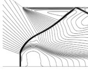
The reflection of a centred compression wave, that converges to a single point on the reflecting surface, is studied and compared with shock reflection. It is shown that the double solution domain, with both regular and Mach reflections, of centred compression wave reflection is enlarged with respect to shock reflection. For centred compression wave reflection, no clear triple point structure exists, and instead, the reflected shock and Mach stem form a smooth curved shock wave. Moreover, the relative Mach stem height, though decreasing almost linearly with the relative wedge trailing edge height as in shock reflection, has a lower bound when the trailing edge height increases, meaning that wedge height variation induced transition, that occurs in shock reflection, does not exist. The existence of this lower bound is due to the fact that beyond a certain value of the wedge trailing edge height, the wedge trailing edge encounters the wedge lower surface that generates the centred compression wave. The present study expands our knowledge of shock reflection, and may be useful for supersonic inlet design.

Type
JFM Papers
Copyright
© The Author(s), 2024. Published by Cambridge University Press

1. Introduction

Shock reflection in both a steady and unsteady flow is an important flow phenomenon (Ben-Dor Reference Ben-Dor2007). Consider just shock reflection in a steady supersonic flow as displayed in figure 1. Both regular reflection (as shown in figure 1a) and Mach reflection (as shown in figure 1b) may occur. The inflow Mach number $M_{0}$ satisfies $M_{0}>1$, a wedge of length $w$ and angle $\theta _{w}$ induces an incident shock wave ($i$), which reflects at the reflecting surface. For regular reflection, the reflection of the incident shock wave ($i$) produces a reflected shock wave ($r$). For Mach reflection, first observed by Mach (Reference Mach1878), the reflection of the incident shock wave ($i$) produces not only a reflected shock wave ($r$) but also a strong shock wave called the Mach stem ($m$), and the three shock waves are connected to a point known as the triple point ($T$), from which a slipline ($s$) is issued. The slipline separates the flow downstream of the reflected shock wave and the flow downstream of the Mach stem. The three shock waves and the slipline separate the flow into four regions (labelled $(0)$, $(1)$, $(2)$ and $(3)$ in figure 1b), the solutions of which in the vicinity of the triple point can be obtained using the three shock theory of Von Neumann (Reference Von Neumann1945).

Figure 1. Shock reflection configuration. (a) Regular reflection. (b) Mach reflection.

Various issues have been studied for steady shock reflection, among which are the criteria for transition to Mach reflection from regular reflection and vice versa, and the structure and size of Mach reflection.

For the first issue, Von Neumann (Reference Von Neumann1943) provided two transition criteria, which are represented by two curves in the plane $(M_{0},\theta _{w})$: one curve is called the detachment criterion and is a sufficient condition for Mach reflection, and the other is the von Neumann criterion and is a necessary condition of Mach reflection. These two curves enclose a region in the plane $(M_{0},\theta _{w})$ called the dual solution domain, within which both reflections may be possible (Henderson & Lozzi Reference Henderson and Lozzi1975; Hornung, Oertel & Sandeman Reference Hornung, Oertel and Sandeman1979). In this dual solution domain, whether we have Mach reflection or regular reflection depends on the history of the building of the actual steady flow. Hysteresis of the reflection type and solution occurs when changing the wedge angle or inflow Mach number from different directions (see Ben-Dor et al. (Reference Ben-Dor, Ivanov, Vasilev and Elperin2002) and Hornung (Reference Hornung2014) for a review of important works related to this subject). In numerical simulation, if a uniform initial flow at the dual solution domain is directly given, regular reflection will initially be observed and will eventually transition to Mach reflection (see, for instance, Mouton & Hornung Reference Mouton and Hornung2007). A regular reflection in the dual solution domain may also transit to Mach reflection through some strong upstream perturbation (Ivanov et al. Reference Ivanov, Klemenkov, Kudryavtsev, Fomin and Kharitonov1997, Reference Ivanov, Markelov, Kudryavtsev and Gimelshein1998; Ivanov, Kudryavtsev & Khotyanovskii Reference Ivanov, Kudryavtsev and Khotyanovskii2000; Kudryavtsev et al. Reference Kudryavtsev, Khotyanovsky, Ivanov and Vandromme2002; Li, Gao & Wu Reference Li, Gao and Wu2011).

For the second issue, one important question is the mechanism to determine the size of Mach reflection configuration. This has been considered as a challenging problem (see Ben-Dor (Reference Ben-Dor2007), p. 53). Hornung & Robinson (Reference Hornung and Robinson1982) argued that the Mach stem height is affected by the pressure decreasing information from the wedge trailing edge expansion fan and postulated a functional form of the Mach stem height, showing that the relative height of the Mach stem depends on the inflow Mach number, the wedge angle, the ratio of specific heats of gas and the relative height of the trailing edge. This functional form has been the basis for many subsequent theoretical modelling starting from the work of Azevedo (Reference Azevedo1989) and Azevedo & Liu (Reference Azevedo and Liu1993). The modelling relies on the use of the triple point solution, the characteristics that bring the trailing edge pressure into the sonic throat below the slipline and a quasi-one-dimensional modelling for flow below the slipline. Since then, more elaboration has been considered to improve the modelling (c.f. Li & Ben-Dor Reference Li and Ben-Dor1997; Mouton & Hornung Reference Mouton and Hornung2007; Gao & Wu Reference Gao and Wu2010; Bai & Wu Reference Bai and Wu2017, Reference Bai and Wu2021; Chernyshov, Savelova & Kapralova Reference Chernyshov, Savelova and Kapralova2021; Choe Reference Choe2022) and to extend to more complex flow (c.f. Schotz et al. Reference Schotz, Levy, Ben-Dor and Igra1997; Grasso & Paoli Reference Grasso and Paoli1999; Shoesmith & Timofeev Reference Shoesmith and Timofeev2021; Vinoth, Sushmitha & Rajesh Reference Vinoth, Sushmitha and Rajesh2022).

Past studies for symmetric shock reflection have mainly considered one incident shock wave. Recently, symmetric steady shock reflection with two incident shock waves have been considered (Guan, Bai & Wu Reference Guan, Bai and Wu2018, Reference Guan, Bai and Wu2020; Guan et al. Reference Guan, Bai, Lin and Wu2020). Both pre-Mach reflection and post-Mach reflection are identified. Pre-Mach reflection means that it is the first incident shock wave that has Mach reflection while the second incident shock will interact with the reflected shock of this reflection. Post-Mach reflection means that it is the second incident shock that has Mach reflection, and the first incident shock wave interacts with the Mach stem of this reflection. In case of pre-Mach reflection, the second incident shock wave elevates the Mach stem and may induce inverse Mach reflection below the von Neumann condition. In case of post-Mach reflection, the first incident shock wave intersects the Mach stem to produce a type IV shock interaction that produces a jet penetrating into the flow duct below the slipline.

Isentropic compression has been used in the design of the Busemann inlet (Busemann Reference Busemann1942), which may produce shockless flow (Miri Reference Miri2012). The full Busemann intake has a very long axial length, so that viscous loss due to a long boundary layer is important. To avoid viscous loss, Ogawa et al. (Reference Ogawa, Moder, Timofeev and Boyce2015) considered truncated and stunted intakes. They observed that this shortening of the intake may produce transition from regular reflection to Mach reflection. They then suggested further investigation for this transition.

The specific purpose of this paper is to study the reflection of a centred compression wave, that is, compression waves that converge to a single point at the reflecting surface. The study of such an ideal configuration not only expands our knowledge of shock reflection but also sheds some light on what could happen in isentropic compression application.

In § 2 the geometry of the wedge is defined to produce the required centred compression wave considered in this paper. Both regular reflection and Mach reflection will be displayed through numerical simulation. In § 3 we follow the transition analysis of shock reflection to derive the detachment condition and the von Neumann condition for centred compression wave reflection. The difference between the transition criteria of centred compression wave reflection and shock reflection, and the reasons for this difference, will be discussed. The study of Mach reflection in centred compression wave reflection will be provided in § 4. The flow structure and the influence of the relative wedge trailing edge height and the total wedge turning angle on the Mach stem height will be discussed, with comparison to the result of shock reflection. Concluding remarks will be provided in § 5. Numerical simulation is carried out for the compressible Euler equations in gas dynamics, using a second-order Roe scheme, in a similar way as in Bai (Reference Bai2023).

2. Reflection of a centred compression wave

Figure 2 displays the configuration for shock reflection considered traditionally and for centred compression wave reflection considered in this paper.

Figure 2. Reflection configuration. (a) Shock wave reflection. (b) Centred compression wave reflection.

2.1. Method to produce a centred compression wave

The centred compression wave is here generated from the lower wedge surface, which has a continuously increasing deflection angle, represented in figure 2(b) by a finite number of Mach waves for clarity.

Let $\theta _{w}$ be the accumulated deflection angle of the lower wedge surface to produce the compression waves. The lower surface producing the centred compression wave can be viewed as having an infinite number of turning or deflection, each with a deflection angle $\Delta \theta _{w}\rightarrow 0$. To define the wedge lower surface shape that produces the required centred compression wave, we adopt a coordinate system with the horizontal axis coinciding with the reflecting surface and the vertical axis passing through the leading edge $A_{1}$ of the wedge.

By centred compression wave reflection we mean all the Mach waves will intersect at a common point $N$ on the reflecting surface, as shown in figure 2(b). The Mach waves all converge to a single point (say $N$) if the coordinates of the wedge lower surface $(x,y)$ satisfy

(2.1)\begin{equation} \tan (\theta +\mu )=\frac{y}{x_{N}-x}, \end{equation}

where $\theta$, with $\tan \theta =-({{\rm d}y}/{{\rm d}\kern0.7pt x})$, is the local wedge angle compared with the horizontal axis (positive if downward) and $\mu =\arcsin ({1}/{M})$ is the Mach angle.

The shape given by (2.1) can also be written more explicitly as

(2.2)\begin{equation} \tan \left(\arcsin \frac{1}{M}-\arcsin \frac{{\rm d}y}{{\rm d}\kern0.7pt x}\right) =\frac{y}{ x_{N}-x}, \end{equation}

where the Mach number $M$ is determined by the Mach wave relation $\nu ( M) -\nu ( M_{0}) =-\theta$, or

(2.3)\begin{equation} \nu (M) -\nu (M_{0}) =\arctan \left(\frac{{\rm d}y}{{\rm d}\kern0.7pt x}\right). \end{equation}

Numerically, the centred compression wave may be represented by a finite number, say $K$, of discrete Mach waves $L_{k}$ with $k=1,2,\ldots,K$, each being produced due to a small wedge deflection ($\Delta \theta _{w}=\theta _{w}/K$) at points $A_{k}$ with $k=1,2,\ldots,K$, as shown in figure 2(b) where only five Mach waves are shown for clarity.

The wedge deflection angle at each discrete point $A_{k}$, compared with the inflow direction, is $\theta _{A_{k}}=k\Delta \theta _{w}$ with $k=1,2,\ldots,K$.

The vertical position $y_{A_{k}}$ at each turning point satisfies the following obvious geometrical relation:

(2.4) \begin{equation} \left\{\begin{array}{@{}l} y_{A_{k}}-y_{A_{k+1}}=(x_{A_{k+1}}-x_{A_{k}}) \tan (k\Delta \theta _{w}),\quad k=1,2,\ldots,K-1, \\ y_{A_{k}}-y_{R}=(x_{R}-x_{A_{k}}) \tan (k\Delta \theta_{w}),\quad k=K. \end{array}\right. \end{equation}

Here $y_{A_{1}}=H_{A_{1}}=H_{A}$ and $H_{A}$ denotes the inlet height.

A Mach wave $L_{k}$ of Mach angle $\mu _{A_{k}}=\arcsin ({1}/{M_{k-1}})$ is produced at $A_{k},$ where $M_{k-1}$ is the Mach number just upstream of the Mach wave generated at $A_{k}$. The Mach number $M_{k}$ is related to the flow deflection angle $\theta _{A_{k}}=k\Delta \theta _{w}$ by the Prandtl–Meyer wave relation applied to the present centred compression wave

(2.5)\begin{equation} \nu (M_{k}) -\nu (M_{0}) ={-}\theta _{A_{k}}, \end{equation}

where $\nu ( M)$ is the well-known Prandtl–Meyer function defined by

(2.6)\begin{equation} \nu (M) =\sqrt{\frac{\gamma +1}{\gamma -1}}\arctan \sqrt{\frac{ \gamma -1}{\gamma +1}(M^{2}-1)}-\arctan \sqrt{M^{2}-1}. \end{equation}

Alternatively, we may also use the differential form of the Mach wave relation

(2.7)\begin{equation} \frac{{\rm d} M}{M}={-}\frac{\left(1+\dfrac{\gamma -1}{2}M^{2}\right){\rm d}\theta } {\sqrt{M^{2}-1}}, \end{equation}

which, after integration, also gives (2.5).

For a centred compression wave, each Mach wave is required to reflect at a common point, here denoted $N(x_{N},0)$, on the reflecting surface, which imposes the following constraint for the horizontal position $x_{A_{k}}$ of $A_{k}$:

(2.8) \begin{equation} \left\{\begin{array}{@{}l} x_{A_{1}}=0, \\ x_{N}-x_{A_{k+1}}=\dfrac{y_{A_{k+1}}}{\tan (\mu _{A_{k+1}}+k\Delta \theta _{w})},\quad k=1,2,\ldots,K-1. \end{array}\right. \end{equation}

Here $x_{N}$, common to all Mach waves, is determined by that of the leading characteristics, i.e.

(2.9)\begin{equation} x_{N}=\frac{y_{A_{1}}}{\tan \mu _{A_{1}}}=\frac{H_{A}}{\tan \mu _{A_{1}}}. \end{equation}

Knowing $x_{A_{1}}=0,$ $y_{A_{1}}=H_{A}$, and given $y_{R}$, the expressions (2.4) and (2.8) can be used to find $x_{A_{2}}$ and $y_{A_{2}}$. More generally, the expressions (2.4) and (2.8) can be solved to give

(2.10) \begin{equation} \left\{\begin{array}{@{}l} x_{A_{k+1}}=\dfrac{y_{A_{k}}+x_{A_{k}}\tan (k\Delta \theta_{w}) -x_{N}\tan (\mu _{A_{k+1}}+k\Delta \theta _{w})}{\tan (k\Delta \theta _{w}) -\tan (\mu _{A_{k+1}}+k\Delta \theta _{w})}, \\ y_{A_{k+1}}=(x_{N}-x_{A_{k+1}}) \tan (\mu_{A_{k+1}}+k\Delta \theta _{w}), \end{array}\right. \end{equation}

so that $x_{A_{k+1}}$ and $y_{A_{k+1}}$ are explicitly related to $x_{A_{k}}$ and $y_{A_{k}}$.

There will be a limit of the allowable deflection angle $\theta _{w}$, and this limit occurs when the last point $A_{K}$ coincides with the trailing edge $R$. This restriction will be considered in § 4.2.

2.2. Numerical evidence of regular and Mach reflection for centred compression wave

Here we use numerical simulation to demonstrate the existence of both regular reflection and Mach reflection. In the meantime we perform a grid convergence study. A regular reflection and a Mach reflection for centred compression wave reflection are displayed in figure 3(a,b), respectively.

Figure 3. Mach number contours for centred compression wave reflection with $M_{0}=4$. (a) Regular reflection ($\theta _{w}=18^{\circ }$, $y_{R}/y_{A_{1}}=0.45$); (b) Mach reflection ($\theta _{w}=30^{\circ }$, $y_{R}/y_{A_{1}}=0.4$).

It is seen that, for regular reflection, there is a single reflected shock, similar to regular reflection of shock reflection. Mach reflection is largely different to that of shock reflection; see § 4.1 for discussions.

We have found that a large number of grids is required to resolve the centred compression wave and the reflected shock wave. To see this, we perform a grid refinement study. When the grid is refined, the wedge lower surface is also refined, in such way that the lower surface satisfies the shape function (2.1) if the grid size vanishes.

Figure 4 shows, for $M_{0}=4$ and $\theta _{w}=30^{\circ }$, the Mach number contours using four different grids of increasing density. Mesh C, which has $2000\times 400$ grid points, produces results very close to those using the denser mesh D. The influence of grid density on the Mach stem height $H_{T}$ is shown in table 1. The Mach stem height $H_{T}$ is defined as the height of the intersection point between the Mach stem and the leading characteristics of the centred compression wave. The Mach stem height varies less than $1.4\times 10^{-3}$ if we replace mesh D with mesh C, so we will use a mesh as dense as mesh C in the following computations.

Figure 4. Mach number contours for $M_{0}=4$, $\theta _{w}=30^{\circ }$ with different meshes. (a) Mesh A, $500\times 100$; (b) mesh B, $1000\times 200$; (c) mesh C, $2000\times 400$; (d) mesh D, $3000\times 600$.

Table 1. Mach stem height for different meshes at $M_{0}=4$ and $\theta _{w}=30^{\circ }$.

3. Transition conditions for the reflection of a centred compression wave

We follow Von Neumann (Reference Von Neumann1943) for shock reflection to derive the von Neumann condition and detachment condition for the reflection of a centred compression wave.

3.1. Transition conditions

Given $M_{0}$ and the total wedge deflection angle $\theta _{w}$, the flow parameters in region (1) of figure 2(b) downstream of the centred compression wave are simply given by the isentropic wave relations

(3.1)\begin{equation} \left\{\begin{array}{@{}c} \nu (M_{1}) -\nu (M_{0}) ={-}\theta _{w}, \\ p_{1}=p_{0}{\left(\dfrac{1+\dfrac{\gamma -1}{2}M_{0}^{2}}{1+ \dfrac{\gamma -1}{2 }M_{1}^{2}}\right)}^{{\gamma }/{(\gamma -1)}}, \end{array}\right. \end{equation}

where $\nu ( M)$ is the Prandtl–Meyer function defined by (2.6).

In case of regular reflection, the flow parameters in the region downstream of the reflected shock, denoted region (2) of figure 2(b), is now given by the oblique shock wave relation with flow deflection angle $\theta _{w}$,

(3.2) \begin{equation} \left\{\begin{array}{@{}c} \tan \theta _{w}=f_{\theta }(M_{1},\beta _{12}), \\ M_{2}=f_{M}(M_{1},\beta _{12}), \\ p_{2}=p_{1}f_{p}(M_{1},\beta _{12}), \end{array}\right. \end{equation}

where

(3.3) \begin{equation} \left\{\begin{array}{@{}l} f_{\theta }({M,\beta })=\dfrac{2({M}^{2}{\sin }^{2}{\beta }-1)}{({M}^{2} (\gamma +\cos {2\beta }) +2) \tan {\beta }}, \\ f_{M}(M,{\beta )}=\sqrt{\dfrac{(\gamma -1) {M}^{2}+2}{2\gamma {M}^{2}{\sin }^{2} {\beta }- (\gamma -1)}+\dfrac{2{M}^{2}{\cos }^{2}{ \beta }}{(\gamma -1) {M}^{2}{\sin }^{2} {\beta }+2}}, \\ f_{p}(M,{\beta )}=1+\dfrac{2\gamma }{\gamma +1}({M}^{2}{\sin }^{2}{ \beta }-1). \end{array}\right. \end{equation}

The detachment condition, denoted as $\theta _{w}=\theta _{w}^{(D)}(M_{0})$, is the value of $\theta _{w}$ such that the reflected shock reaches the detachment condition, i.e.

(3.4)\begin{equation} \tan \theta _{w}^{(D)}(M_{0})=\frac{2[(M_{1}^{2}-1)\tan ^{2} \beta_{m}-1]}{\tan \beta _{m}[(\gamma M_{1}^{2}+2)(1+\tan ^{2} \beta _{m})+M_{1}(1-\tan ^{2}\beta _{m})]}, \end{equation}

where $\beta _{m}$, given by

(3.5)\begin{equation} \sin ^{2}\beta _{m}=\frac{1}{\gamma M_{1}^{2}}\left[\frac{\gamma +1}{4} M_{1}^{2}-1+\sqrt{(1+\gamma )\left(1+\frac{\gamma -1}{2}M_{1}^{2}+\frac{\gamma +1 }{16}M_{1}^{4}\right)}\right], \end{equation}

is the shock angle $\beta$ at which ${{\rm d}\theta }/{{\rm d}\beta }$ vanishes.

The von Neumann condition is the condition for $\theta _{w}$, denoted as $\theta _{w}=\theta _{w}^{(N)}(M_{0})$, such that the pressure $p_{2}$ determined by (3.2) is equal to the pressure $p_{N}$ of a normal shock wave connecting to region $(0)$, i.e.

(3.6)\begin{equation} p_{2}=p_{N}=p_{0}\,f_{p}\left(M_{0},\frac{\rm \pi}{2}\right) \end{equation}

The transition criteria in the $M_{0}-\theta _{w}$ are displayed in figure 5, where we also show the transition criteria for conventional shock reflection. We observe that the von Neumann condition for centred compression wave reflection is lower than that for shock reflection, and, in contrast, the detachment condition for centred compression wave reflection is higher than that for shock reflection. Thus, the double solution domain for the centred compression wave reflection is larger than that for shock reflection.

Figure 5. Transition criteria, in the $M_{0}-\theta _{w}$ plan, for centred compression wave (CCW) reflection, compared with the transition criteria for shock wave reflection.

The observed difference between centred compression wave reflection and shock reflection can be heuristically understood. It is well known that to achieve the same flow deflection angle, isentropic Mach wave compression gives a larger pressure jump and a smaller Mach number decrease than shock compression, meaning that region (1) has a higher pressure and higher Mach number with centred compression wave reflection than that with a shock reflection. Thus, centred compression wave reflection has the same effect on reflection than shock reflection with a larger $\theta _{w}$. As a result, the transition curves for centred compression wave reflection could be seen as a shift to the left and compression of the transition curves for shock wave reflection, thus enlarging the double solution domain at the same abscissa.

The difference between centred compression wave reflection and shock reflection can also be explained using shock polars. Figure 6(a,b) gives the shock polars for $\theta _{w}=20^{\circ }$ and $\theta _{w}=27^{\circ }$, both with $M_{0}=4$.

Figure 6. Shock polars for centred compression wave (CCW) reflection, with $M_{0}=4$. Results are shown for (a) $\theta _{w}=20^{\circ }$ and (b) $\theta _{w}=27^{\circ }$. RR - Regular reflection; MR - Mach reflection.

At $\theta _{w}=20^{\circ }$, shock polars for shock reflection, marked with dashed lines, only permit regular reflection. The polar representing the reflected shock wave may intersect the axis (regular reflection) but not the strong part (upper branch) of the polar from the origin. Shock polars for centred compression wave reflection, marked with solid lines, however, allow both regular reflection and Mach reflection. According to figure 5, the condition with $M_{0}=4$ and $\theta _{w}=20^{\circ }$ lies at the regular reflection domain for shock reflection and the double solution domain for centred compression wave reflection.

At $\theta _{w}=27^{\circ }$, shock polars for shock reflection, marked with dashed lines, only permit Mach reflection. The polar representing the reflected shock wave can not intersect the axis but can intersect the strong part (upper branch) of the polar from the origin. Shock polars for centred compression wave reflection, marked with solid lines, however, allow both regular reflection and Mach reflection. According to figure 5, the condition with $M_{0}=4$ and $\theta _{w}=27^{\circ }$ lies at the Mach reflection domain for shock reflection and the double solution domain for centred compression wave reflection.

In the following we use numerical simulation to verify the conclusion from transition analysis.

3.2. Numerical verification of transition conditions

Numerical simulation is carried out for $M_{0}=4$ with a series of wedge deflection angles $\theta _{w}$, which span the Mach reflection region, double solution region and regular reflection region shown in figure 5 for both centred compression wave reflection and shock wave reflection. In case it is possible to have a double solution, there are various ways to get both regular reflection and Mach reflection. According to the studies for hysteresis phenomenon in transition (Ben-Dor et al. Reference Ben-Dor, Ivanov, Vasilev and Elperin2002; Hornung Reference Hornung2014), we may use a regular reflection solution (obtained for smaller $\theta _{w}$) as an initial condition to get regular reflection in the dual solution domain and a Mach reflection solution (obtained for larger $\theta _{w}$) as an initial condition to get Mach reflection in the dual solution domain. Using a uniform flow with $M_{0}=4$ everywhere as an initial solution, the steady solution of numerical simulation gives regular reflection in the double solution domain (Mouton & Hornung Reference Mouton and Hornung2007). To further demonstrate the possibility of Mach reflection, a Mach reflection solution with a lower Mach number, say $M_{0}=3$, is used as an initial solution and the numerical simulation is carried out with $M_{0}=4$ as the inflow condition until a steady solution is obtained.

The Mach number contours from numerical simulation with $M_{0}=4$ and $\theta _{w}=18^{\circ },20^{\circ },23^{\circ },27^{\circ }$ and $30^{\circ }$ are displayed in figure 7 for centred compression wave reflection and in figure 8 for shock reflection. The difference can also be seen from the hysteresis loop shown in figure 9 (more discussion about the Mach stem height will be discussed in the next section).

Figure 7. Mach contours for centred compression wave reflection, showing the regular reflection domain ($\theta _{w}=18^{\circ }$), double solution domain ($\theta _{w}=20^{\circ },23^{\circ }$ and $27^{\circ }$) and Mach reflection domain ($\theta _{w}=30^{\circ }$), with $M_{0}=4$.

Figure 8. Mach contours for shock reflection, showing the regular reflection domain ($\theta _{w}=20^{\circ }$), double solution domain ($\theta _{w}=22^{\circ },23^{\circ }$ and $24^{\circ }$) and Mach reflection domain ($\theta _{w}=26^{\circ }$), with $M_{0}=4$.

Figure 9. The hysteresis loop in the $(H_{T}/H_{A}-\theta _{w})$ (where $H_{T}$ denotes the Mach stem height and $H_{A}$ denotes the inlet height) plane with $M_{0}=4$. (a) Shock reflection, (b) centred compression wave reflection.

For centred compression wave reflection with $M_{0}=4$, the double solution lies in $19.43^{\circ }<\theta _{w}<28.80^{\circ }$ according to the critical condition displayed in figure 5.

For $\theta _{w}=18^{\circ }$, we only have regular reflection according to the critical condition displayed in figure 5. Numerically, we indeed only observe regular reflection and the numerical result is displayed in figure 7(a).

For $\theta _{w}=20^{\circ }$, we should have both regular and Mach reflection according to figure 5. As shown in figure 7(b,h), we indeed have both regular reflection and Mach reflection.

For $\theta _{w}=23^{\circ }$, we also should have both regular and Mach reflection according to figure 5. As shown in figure 7(c,g), we indeed have both regular reflection and Mach reflection.

For $\theta _{w}=27^{\circ }$, we also should have both regular and Mach reflection according to figure 5. As shown in figure 7(d,f), we indeed have both regular reflection and Mach reflection.

For $\theta _{w}=30^{\circ }$, we should have only Mach reflection according to figure 5. Numerically we indeed only obtain Mach reflection and the numerical result is shown in figure 7(e).

For shock reflection with $M_{0}=4$, the double solution lies in $20.85^{\circ }<\theta _{w}<25.61^{\circ }$ according to the classical von Neumann condition and detachment condition. The numerical results displayed in figure 8) show that the double solution occurs for $\theta _{w}=22^{\circ },23^{\circ }$ and $24^{\circ }$, while for $\theta _{w}=20^{\circ }$, we only have regular reflection and, for $\theta _{w}=26^{\circ }$, we only have Mach reflection.

4. Mach reflection configuration in centred compression wave reflection

In this section we use numerical simulation to study Mach reflection for a centred compression wave. First we clarify the structure of Mach reflection that is distinctive from Mach reflection by shock wave. Second we consider the influence of the wedge trailing edge relative height $g={y_{R}}/{H_{A}}$ on the Mach stem height and possible transition. Lastly, we consider the Mach stem height when the flow deflection angle $\theta _{w}$ of the centred compression wave increases.

4.1. Mach reflection that lacks a clear triple point

It is well known that, for Mach reflection by a shock wave, there is a triple point that connects the incident shock, a reflected shock, a Mach stem and a slipline. All these four discontinuities have a different angle in the vicinity of the triple point (see, for instance, figure 8eh). The flow between the slipline and the reflecting surface form a convergent–divergent duct that is quasi-one-dimensional.

However, the Mach reflection configuration of a centred comnpression wave, as shown in figure 7(eh), displays the following differing features. (a) The reflected shock is highly curved by the centred compression wave. These compression waves weaken the reflected shock wave, since they are from the opposite family. (b) The Mach stem appears to result simply from the reflection of the leading Mach wave. However, this is possible only if the Mach stem is an inverted one. Although the curvature of the Mach stem can not be clearly identified, it can be argued that it is an inverted Mach stem. Note that the inverted Mach stem is convex towards the upstream direction and that the initial angle of the slipline is negative (Henderson & Lozzi Reference Henderson and Lozzi1979; Hornung Reference Hornung1986; Hekiri & Emanuel Reference Hekiri and Emanuel2015). (c) There is no clear triple point, the reflected shock and Mach stem appear to form a single curved shock and there is no distinct slipline (rather there are shear layers). (d) The flow below the slipline is far from being quasi-one-dimensional. It is divergent in the initial part and is then convergent. The divergent part increases the pressure to balance the pressure increase of the impinging compression Mach waves, while the convergent part decreases the pressure to balance the pressure decrease due to the impinging wedge trailing edge expansion wave.

4.2. Influence of $g$ and absence of wedge height induced transition

For shock reflection, it has been shown that when the relative wedge trailing edge height $g$ is small, the relative Mach stem height ${H_{T}}/{H_{A}}$ (where $H_{A}=y_{A}$ is the inlet height) decreases almost linearly with $g$ (Li & Ben-Dor Reference Li and Ben-Dor1997; Schotz et al. Reference Schotz, Levy, Ben-Dor and Igra1997). This means that Mach reflection may transit to regular reflection by increasing $g$. Vuillon, Zeiton & Ben-Dor (Reference Vuillon, Zeiton and Ben-Dor1995) anticipated that such transition occurs before the wedge trailing edge expansion fan interacts with the incident shock. Later on, Li & Ben-Dor (Reference Li and Ben-Dor1997) found that this transition occurs after the wedge trailing edge expansion fan interacts with the incident shock. Bai (Reference Bai2023) determined the shape of the incident shock during interaction and found the exact condition for transition. Due to the interaction between the wedge trailing edge expansion fan and the incident shock, so the incident shock is weakened and the Mach stem height decreases with $g$ more slowly than a linear curve.

One would expect that, for centred compression wave reflection, we have a similar phenomenon, i.e. Mach reflection to regular reflection transition should occur for some large enough $g$. But, as we shall see, this does not happen.

Figure 10 displays, for $M_{0}=4$, $\theta _{w}=30^{\circ }$, the Mach stem heights for different $g$. Figure 11 show the Mach number contour lines. We observe that $H_{T}/H_{A}$ varies almost linearly with $g$, i.e. it holds that

(4.1)\begin{equation} \frac{H_{T}}{H_{A}}\approx Ag+B, \end{equation}

where $A$ and $B$ are independent of $g$. According to figure 10, the linear curve (4.1) would intersect the axis $g$ if $g$ goes beyond $0.498$. However, such a direct intersection is impossible.

Figure 10. Mach stem height as a function of $g$, with $M_{0}=4$ and $\theta _{w}=30^{\circ }$.

Figure 11. Mach contours for $M_{0}=4$, $\theta _{w}=30^{\circ }$ with different $g$. Results are shown for (a) $g=0.35$, (b) $g=0.375$, (c) $g=0.4$, (d) $g=0.41$.

In shock reflection the wedge trailing edge expansion fan prevents the direct intersection of a similar linear curve (4.1) with the $g$ axis. In fact, interaction between this expansion fan and the incident shock occurs when $g>g_{max}$, with

(4.2a,b)\begin{equation} g_{max }=\frac{h_{max }/w}{h_{max }/w+\sin \theta _{w}},\quad \frac{h_{max }}{w }=\frac{\cos \theta _{w}\tan \beta _{01}-\sin \theta _{w}}{\tan (\theta _{w}+\mu _{1}) -\tan \beta _{01}}\tan (\theta _{w}+\mu_{1}) \end{equation}

according to Li & Ben-Dor (Reference Li and Ben-Dor1997) and Bai (Reference Bai2023). Here $\mu _{1}$ is the Mach angle in region (1) of figure 1, $\beta _{01}$ is the shock angle of the incident shock wave. Due to this interaction, the linear decrease (4.1) is replaced by a nonlinear curve (see figures 9 and 14 of Bai Reference Bai2023).

For centred compression wave reflection, we only have linear variation as given by (4.1) and have no intersection, according to figure 10. In other words, we have pure linear variation as given by (4.1) for some small values of $g$ and for larger $g$, there is no solution!

In the case of centred compression wave reflection, the last Mach wave of the centred compression wave is parallel to the leading characteristics of the trailing edge expansion fan, since between two simple waves (here the compression Mach waves and the wedge trailing edge expansion fan) is one uniform flow region where the characteristics lines are parallel. Hence, no interaction between the centred compression wave and the trailing edge expansion fan occurs. But this does not mean that the curve (4.1) can intersect the axis $g$ more easily than in shock reflection. In fact, it does not intersect the axis $g$ at all. The reason is given below.

When $g$ increases, the last point (as point $A_{5}$ in figure 2) of the wedge deflection part that produces the centred compression wave will approach the trailing edge (R). Assume that these two points coincide at $g=g_{max}$, i.e. $g_{max}$ is the value of $g$ at which the last point ( $x_{A_{K}}$,$y_{A_{K}}$) given by (2.10) coincides with the trailing edge $(x_{R},y_{R})$. This means that the maximum allowable value of $g$ is restricted by the encounter of the last point $A_{K}$ with the trailing edge (R).

Figure 12 gives the maximum values $g_{max}$. Not enough compression waves can be produced when $g>g_{max}$. For the present case shown in figure 10, with $M_{0}=4$, $\theta _{w}=30^{\circ }$, we have $g_{max}\approx 0.426$ according to figure 12, which is far below $g=0.498$ required for intersection in figure 10.

Figure 12. The maximum value $g=g_{max}$ at which the last characteristics line of the centred compression wave coincide with the leading characteristics line of the trailing edge expansion wave.

In summary, for shock reflection with large $g$, it is the interaction between the wedge trailing edge expansion fan with the incident shock that prevents the intersection of a linear curve (4.1) with the axis $g$, while for centred compression wave reflection, when $g$ goes beyond some threshold shown in figure 12, the encounter of the last point ($x_{A_{K+1}}$, $y_{A_{K+1}}$) given by (2.10) with the trailing edge $(x_{R},y_{R})$ prevents any increase in $g$ at which the linear curve (4.1) intersects the axis $g$. However, transition from Mach reflection to regular reflection due to increasing $g$ can still occur for shock reflection, while this transition does not occur in centred compression wave reflection.

4.3. Influence of $\theta _{w}$

It is well known that, keeping other flow parameters fixed, increasing $\theta _{w}$ (or the shock angle of the incident shock wave) will increase the Mach stem height for shock reflection (see Hornung & Robinson Reference Hornung and Robinson1982). It is interesting to see whether the Mach stem height is increased or reduced when the incident shock is replaced by a centred compression wave.

For $M_{0}=4$, the Mach stem height variations as a function of the wedge angle $\theta _{w}$ are shown in figure 13 for both centred compression wave reflection and shock wave reflection, with $g=0.4$ and $0.45$.

Figure 13. Mach stem heights for centred compression wave reflection and shock wave reflection with $M_{0}=4$. Results are shown for (a) $g=0.4$ and (b) $g=0.45$.

We observed the following two phenomena.

  1. (1) For centred compression wave reflection, the relative Mach stem height $H_{T}/H_{A}$ varies with $\theta _{w}$ much more slowly than for shock reflection.

  2. (2) For $\theta _{w}$ larger than some value, the relative Mach stem height $H_{T}/H_{A}$ for centred compression wave reflection is smaller than that for shock reflection, while for $\theta _{w}$ smaller than some value, the relative Mach stem height $H_{T}/H_{A}$ for centred compression wave reflection is larger than for shock reflection.

We have shown in § 3 that, for centred compression wave reflection, the von Neumann condition in terms of $\theta _{w}$ is lower than that for shock reflection. Thus, below the von Neumann condition of shock reflection and above the von Neumann condition of centred compression wave reflection, we have a finite height of the Mach stem in centred compression wave reflection. This is why for relatively small $\theta _{w}$, the Mach stem height is higher in centred compression wave reflection than in shock reflection. For a higher value of $\theta _{w}$, we fail to find a simple reason to explain why shock reflection has a higher Mach stem than in centred compression wave reflection.

5. Concluding remarks

We have studied reflection of a centred compression wave in steady supersonic flow and compared the difference between centred compression wave reflection and shock reflection. As in shock reflection, both regular reflection and Mach reflection exist. The von Neumann condition and detachment condition for centred compression wave reflection are obtained in a similar way as in shock reflection. The Mach reflection configuration and the size of the Mach stem height are studied numerically.

It is shown that, in the $\theta _{w}$$M_{0}$ plane, the von Neuman condition of centred compression wave reflection is lower than that of shock reflection, while the detachment condition is higher, i.e. the double solution domain is larger in centred compression wave reflection.

The Mach reflection configuration of centred compression wave reflection is found to contain a single shock wave instead of three shock waves in Mach reflection of shock reflection, though one part could be considered as the Mach stem and the rest as the reflected shock. The flow duct below the slipline has a divergent part followed by a convergent part, to balance the pressure of the incident compression waves and the pressure of the wedge trailing edge expansion fan. Since the so-called Mach stem is directly produced by the leading characteristics of the centred compression wave, it is necessarily an inverted Mach stem.

It is found numerically that the relative Mach stem height $(H_{T}/H_{A})$ decreases almost linearly with the relative wedge trailing edge height $(g)$, similarly as in shock reflection. We find the existence of a maximum value of $g$ above which the last point of the wedge lower surface generating the centred compression wave encounters the wedge trailing edge and, as a result, this linear curve can not intersect the axis $g$. This is different to shock reflection, for which there is a maximum value of $g$ above which the wedge trailing edge expansion fan interacts with the incident shock. Moreover, no Mach reflection to regular reflection occurs by increasing $g$, and we simply do not have a solution for large $g$. This is different from shock reflection, where Mach reflection to regular reflection occurs for large $g$.

The Mach stem height increases with the wedge deflection angle ($\theta _{w}$) much more slowly than in shock reflection. For $\theta _{w}$ smaller than some value, the Mach stem height of centred compression wave reflection is higher than that of shock reflection, while for $\theta _{w}$ larger than some value, this trend is reversed.

For shock reflection, a number of studies have been devoted to estimate the height of the Mach stem height. However, since the flow below the slipline is highly two dimensional, it would be challenging to work out a Mach stem height model for the present centred compression wave reflection.

Acknowledgements

The author is grateful to all the three referees who provided valuable comments to help improve the paper greatly.

Funding

This work was supported by the Young Elite Scientist Sponsorship Program by CAST (no. YESS20210042), the National Natural Science Foundation of China (no. 52192632), National Key Project GJXM92579 and the Young Talent Support Plan of Beihang University.

Declaration of interests

The author reports no conflict of interest.

References

Azevedo, D.J. 1989 Analytical prediction of shock patterns in a high-speed wedge bounded duct. PhD thesis, Dept. Mech. & Aero. Engng, State University.Google Scholar
Azevedo, D.J. & Liu, C.S. 1993 Engineering approach to the prediction of shock patterns in bounded high-speed flows. AIAA J. 31, 8390.Google Scholar
Bai, C.Y. 2023 Shock reflection with incident shock/wedge trailing edge expansion fan interaction. J. Fluid Mech. 968, A21.CrossRefGoogle Scholar
Bai, C.Y. & Wu, Z.N. 2017 Size and shape of shock waves and slipline for Mach reflection in steady flow. J. Fluid Mech. 818, 116140.CrossRefGoogle Scholar
Bai, C.Y. & Wu, Z.N. 2021 A study of the dependence of the Mach stem height on the trailing edge height. Fluids 6 (9), 313.Google Scholar
Ben-Dor, G. 2007 Shock Wave Reflection Phenomena. Springer.Google Scholar
Ben-Dor, G., Ivanov, M., Vasilev, E.I. & Elperin, T. 2002 Hysteresis processes in the regular reflection to Mach reflection transition in steady flows. Prog. Aerosp. Sci. 38, 347387.CrossRefGoogle Scholar
Busemann, A. 1942 Die achsensymmetrische kegelige Uberschallstromung. Luftfahrtforschung 19, 137144.Google Scholar
Chernyshov, M.V., Savelova, K.E. & Kapralova, A.S. 2021 Approximate analytical models of shock-wave structure at steady Mach reflection. Fluids 6, 305.Google Scholar
Choe, S.G. 2022 A method for predicting Mach stem height in steady flows. Proc. Inst. Mech. Engrs. G 236 (1), 310.Google Scholar
Gao, B. & Wu, Z.N. 2010 A study of the flow structure for Mach reflection in steady supersonic flow. J. Fluid Mech. 656, 2950.Google Scholar
Grasso, F. & Paoli, R. 1999 An analytical study of Mach reflection in nonequilibrium steady flows. Phys. Fluids 11 (10), 31503167.Google Scholar
Guan, X.K., Bai, C.Y., Lin, J. & Wu, Z.N. 2020 Mach reflection promoted by an upstream shock wave. J. Fluid Mech. 903, A44.Google Scholar
Guan, X.K., Bai, C.Y. & Wu, Z.N. 2018 Steady Mach reflection with two incident shock waves. J. Fluid Mech. 855, 882909.Google Scholar
Guan, X.K., Bai, C.Y. & Wu, Z.N. 2020 Double solution and influence of secondary waves on transition criteria for shock interference in pre-Mach reflection with two incident shock waves. J. Fluid Mech. 887, A22.Google Scholar
Hekiri, H. & Emanuel, G. 2015 Structure and morphology of a triple point. Phys. Fluids 27, 056102.Google Scholar
Henderson, L.F. & Lozzi, A. 1975 Experiments on transition of Mach reflection. J. Fluid Mech. 68, 139155.Google Scholar
Henderson, L.F. & Lozzi, A. 1979 Further experiments on transition to Mach reflexon. J. Fluid Mech. 94, 541559.CrossRefGoogle Scholar
Hornung, H.G. 1986 Regular and Mach reflections of shock waves. Annu. Rev. Fluid Mech. 18, 3358.Google Scholar
Hornung, H.G. 2014 Mach reflection in steady flow. I. Mikhail Ivanov's contributions. II. Caltech stability experiments. AIP Conf. Proc. 1628, 13841393.CrossRefGoogle Scholar
Hornung, H.G., Oertel, H. & Sandeman, R.J. 1979 Transition to Mach reflection of shock waves in steady and pseudo-steady flows with and without relaxation. J. Fluid Mech. 90, 541560.Google Scholar
Hornung, H.G. & Robinson, M.L. 1982 Transition from regular to Mach reflection of shock waves. Part 2. The steady-flow criterion. J. Fluid Mech. 123, 155164.CrossRefGoogle Scholar
Ivanov, M.S., Klemenkov, G.P., Kudryavtsev, A.N., Fomin, V.M. & Kharitonov, A.M. 1997 Experimental investigation of transition to Mach reflection of steady shock waves. Dokl. Akad. Nauk 357 (5), 623627.Google Scholar
Ivanov, M.S., Kudryavtsev, A.N. & Khotyanovskii, D.V. 2000 Numerical simulation of the transition between the regular and Mach reflection of shock waves under the action of local perturbations. Dokl. Phys. 45 (7), 353357.CrossRefGoogle Scholar
Ivanov, M.S., Markelov, G.N., Kudryavtsev, A.N. & Gimelshein, S.E. 1998 Numerical analysis of shock wave reflection transition in steady flows. AIAA J. 36, 20792086.Google Scholar
Kudryavtsev, A.N., Khotyanovsky, D.V., Ivanov, M.S. & Vandromme, D. 2002 Numerical investigations of transition between regular and Mach reflections caused by free-stream disturbances. Shock Waves 1 (2), 157165.Google Scholar
Li, H. & Ben-Dor, G. 1997 A parametric study of Mach reflection in steady flows. J. Fluid Mech. 341, 101125.Google Scholar
Li, S.G., Gao, B. & Wu, Z.N. 2011 Time history of regular to Mach reflection transition in steady supersonic flow. J. Fluid Mech. 682, 160184.Google Scholar
Mach, E. 1878 Uber den verlauf von Funkenwellen in der Ebene und im Raume. Sitz.ber. Akad. Wiss. Wien 78, 819838.Google Scholar
Miri, S.H. 2012 Shock-less hypersonic intakes. Theses and dissertations. Paper 1361.Google Scholar
Mouton, C.A. & Hornung, H.G. 2007 Mach stem height and growth rate predictions. AIAA J. 45, 19771987.Google Scholar
Ogawa, H., Moder, S., Timofeev, E.V. & Boyce, R.R. 2015 Startability and Mach reflection hysteresis of shortened Busemann intakes for axisymmetric scramjet engines. In 29th International Symposium on Shock Waves 1. ISSW 2013 (ed. R. Bonazza & D. Ranjan). Springer.Google Scholar
Schotz, M., Levy, A., Ben-Dor, G. & Igra, O. 1997 Analytical prediction of the wave configuration size in steady flow Mach reflections. Shock Waves 7 (6), 363372.CrossRefGoogle Scholar
Shoesmith, B. & Timofeev, E. 2021 Modelling of Mach reflections in internal axisymmetric steady supersonic flow. Shock Waves 31 (8), 945957.Google Scholar
Vinoth, P., Sushmitha, J. & Rajesh, G. 2022 Prediction of Mach stem height in compressible open jets. Part 1. Overexpanded jets. J. Fluid Mech. 942, A48.Google Scholar
Von Neumann, J. 1943 Oblique reflection of shock. Explos. Res. Rep. 12. Navy Dept., Bureau of Ordinance.Google Scholar
Von Neumann, J. 1945 Refraction, intersection and reflection of shock waves. NAVORD Rep. 203–245. Navy Dept., Bureau of Ordinance.Google Scholar
Vuillon, J., Zeiton, D. & Ben-Dor, G. 1995 Reconstruction of oblique shock wave reflection in steady flows. Part 2. Numerical investigation. J. Fluid Mech. 301, 3750.CrossRefGoogle Scholar
Figure 0

Figure 1. Shock reflection configuration. (a) Regular reflection. (b) Mach reflection.

Figure 1

Figure 2. Reflection configuration. (a) Shock wave reflection. (b) Centred compression wave reflection.

Figure 2

Figure 3. Mach number contours for centred compression wave reflection with $M_{0}=4$. (a) Regular reflection ($\theta _{w}=18^{\circ }$, $y_{R}/y_{A_{1}}=0.45$); (b) Mach reflection ($\theta _{w}=30^{\circ }$, $y_{R}/y_{A_{1}}=0.4$).

Figure 3

Figure 4. Mach number contours for $M_{0}=4$, $\theta _{w}=30^{\circ }$ with different meshes. (a) Mesh A, $500\times 100$; (b) mesh B, $1000\times 200$; (c) mesh C, $2000\times 400$; (d) mesh D, $3000\times 600$.

Figure 4

Table 1. Mach stem height for different meshes at $M_{0}=4$ and $\theta _{w}=30^{\circ }$.

Figure 5

Figure 5. Transition criteria, in the $M_{0}-\theta _{w}$ plan, for centred compression wave (CCW) reflection, compared with the transition criteria for shock wave reflection.

Figure 6

Figure 6. Shock polars for centred compression wave (CCW) reflection, with $M_{0}=4$. Results are shown for (a) $\theta _{w}=20^{\circ }$ and (b) $\theta _{w}=27^{\circ }$. RR - Regular reflection; MR - Mach reflection.

Figure 7

Figure 7. Mach contours for centred compression wave reflection, showing the regular reflection domain ($\theta _{w}=18^{\circ }$), double solution domain ($\theta _{w}=20^{\circ },23^{\circ }$ and $27^{\circ }$) and Mach reflection domain ($\theta _{w}=30^{\circ }$), with $M_{0}=4$.

Figure 8

Figure 8. Mach contours for shock reflection, showing the regular reflection domain ($\theta _{w}=20^{\circ }$), double solution domain ($\theta _{w}=22^{\circ },23^{\circ }$ and $24^{\circ }$) and Mach reflection domain ($\theta _{w}=26^{\circ }$), with $M_{0}=4$.

Figure 9

Figure 9. The hysteresis loop in the $(H_{T}/H_{A}-\theta _{w})$ (where $H_{T}$ denotes the Mach stem height and $H_{A}$ denotes the inlet height) plane with $M_{0}=4$. (a) Shock reflection, (b) centred compression wave reflection.

Figure 10

Figure 10. Mach stem height as a function of $g$, with $M_{0}=4$ and $\theta _{w}=30^{\circ }$.

Figure 11

Figure 11. Mach contours for $M_{0}=4$, $\theta _{w}=30^{\circ }$ with different $g$. Results are shown for (a) $g=0.35$, (b) $g=0.375$, (c) $g=0.4$, (d) $g=0.41$.

Figure 12

Figure 12. The maximum value $g=g_{max}$ at which the last characteristics line of the centred compression wave coincide with the leading characteristics line of the trailing edge expansion wave.

Figure 13

Figure 13. Mach stem heights for centred compression wave reflection and shock wave reflection with $M_{0}=4$. Results are shown for (a) $g=0.4$ and (b) $g=0.45$.