Hostname: page-component-78c5997874-94fs2 Total loading time: 0 Render date: 2024-11-19T06:32:40.348Z Has data issue: false hasContentIssue false

Global receptivity analysis: physically realizable input–output analysis

Published online by Cambridge University Press:  03 February 2023
Omar Kamal*
Affiliation:
Department of Mechanical and Civil Engineering, California Institute of Technology, Pasadena, CA 91125, USA
Matthew T. Lakebrink
Affiliation:
The Boeing Company, Hazelwood, MO 63042, USA
Tim Colonius
Affiliation:
Department of Mechanical and Civil Engineering, California Institute of Technology, Pasadena, CA 91125, USA
*
Email address for correspondence: [email protected]

Abstract

In the context of transition analysis, linear input–output analysis determines the worst-case disturbances to a laminar base flow based on a generic right-hand-side volumetric/boundary forcing term. The worst-case forcing is not physically realizable, and, to our knowledge, a generic framework for posing physically realizable worst-case disturbance problems is lacking. In natural receptivity analysis, disturbances are forced by matching (typically local) solutions within the boundary layer to outer solutions consisting of free-stream vortical, entropic and acoustic disturbances. We pose a scattering formalism to restrict the input forcing to a set of realizable disturbances associated with plane-wave solutions of the outer problem. The formulation is validated by comparing with direct numerical simulations of a Mach 4.5 flat-plate boundary layer. We show that the method provides insight into transition mechanisms by identifying those linear combinations of plane-wave disturbances that maximize energy amplification over a range of frequencies. We also discuss how the framework can be extended to accommodate scattering from shocks and in shock layers for supersonic flow.

Type
JFM Rapids
Copyright
© The Author(s), 2023. Published by Cambridge University Press

1. Introduction

Boundary-layer receptivity analyses determine how free-stream vortical, entropic and acoustic waves excite instabilities. Several approaches have been developed to accomplish this inner-to-outer matching, such as forcing a flat-plate boundary layer with an induced travelling wave having the frequency of an incident acoustic wave and a wavenumber associated with surface irregularities (Crouch Reference Crouch1992). However, many studies (Goldstein Reference Goldstein1983; Duck, Ruban & Zhikharev Reference Duck, Ruban and Zhikharev1996; Qin & Wu Reference Qin and Wu2016; Ruban, Keshari & Kravtsova Reference Ruban, Keshari and Kravtsova2021) still rely upon asymptotic expansions, which often require additional approximations, such as restrictions to low frequencies (Fedorov Reference Fedorov2003). Although direct numerical simulations (DNS) can alleviate these challenges, many (expensive) calculations are needed to characterize the dominant natural receptivity mechanisms. This is especially apparent for design problems, where the inverse study is often more useful: What are the worst-case disturbances that lead to maximal amplification?

Input–output analysis provides a framework for this kind of optimization problem by determining surface or volumetric inhomogeneities, i.e. inputs, that lead to maximal amplification of disturbances, i.e. outputs. Trefethen et al. (Reference Trefethen, Trefethen, Reddy and Driscoll1993) introduced studying the pseudospectra of the ‘linearized Navier–Stokes evolution’ operator as a tool for understanding non-modal amplification of disturbances in Couette and Poiseuille flows. Monokrousos et al. (Reference Monokrousos, Åkervik, Brandt and Henningson2010) used the input–output framework to determine optimal amplification in the spatially evolving flat-plate boundary layer, and it has subsequently been used in a variety of contexts, including extensions to computing optimal disturbances in turbulent mean flows (Schmidt et al. Reference Schmidt, Towne, Rigas, Colonius and Brès2018). The framework has also been adapted to high-speed compressible flows (Nichols & Lele Reference Nichols and Lele2011; Bugeat et al. Reference Bugeat, Chassaing, Robinet and Sagaut2019; Nichols & Candler Reference Nichols and Candler2019; Bae, Dawson & McKeon Reference Bae, Dawson and McKeon2020; Cook et al. Reference Cook, Knutson, Nichols and Candler2020; Lugrin et al. Reference Lugrin, Beneddine, Leclercq, Garnier and Bur2021; Cook & Nichols Reference Cook and Nichols2022). Furthermore, there have been contemporary methodological advancements pertaining to the nature of the optimal forcing, such as using sparsity-promoting norms in computing localized forcing structures (Skene et al. Reference Skene, Yeh, Schmid and Taira2022).

However, while the inputs can be readily restricted to subspaces by, for example, forcing only in certain equations (mass, momentum or energy), and/or in certain flow regions (e.g. Jeun, Nichols & Jovanović Reference Jeun, Nichols and Jovanović2016), the resulting inhomogeneous problem is not physically realizable, in the sense that the sources are unconnected to any physical mechanism that produces them. In this work, we employ a scattering formalism to restrict input–output analysis to forcings that are associated with free-stream disturbances. We decompose the full linear solution into an incident component, representing vortical, entropic or acoustic disturbances to the free stream, and a scattered (or residual) component that is forced by the incident wave propagated through the linearized equations. This forcing approaches zero in the free stream where the incident waves satisfy the governing equations, but is non-zero within the shock- and boundary-layer regions, where it can be parametrized and optimized using the standard input–output (singular value decomposition) framework. This permits natural receptivity analysis to be performed directly in the global framework without recourse to asymptotic analysis (though with its own challenges, as we discuss).

The global optimal receptivity formalism is developed in § 2, after which the problem is simplified to high-speed flow over a two-dimensional (2-D) flat plate (ignoring any shock) in order to validate the methodology with previous results. In § 3, we employ the input–output scattering formalism with various free-stream waves and analyse the corresponding responses. Thereafter, we compute the optimal incident waves that maximize 2-D disturbance-energy amplification for a Mach 4.5 flat-plate boundary layer over a range of frequencies, showing how the input–output framework complements and extends traditional receptivity theory. In § 4, we summarize and discuss future work.

2. Methodology

2.1. Scattering ansatz

We begin with the non-dimensional, fully compressible Navier–Stokes equations, linearized about a time-independent base flow, such that

(2.1)\begin{equation} \boldsymbol{q}(x,y,z,t)=\bar{\boldsymbol{q}}(x,y,z)+\boldsymbol{q}'(x,y,z,t), \end{equation}

where $\boldsymbol {q}=[\rho,u,v,w,T]^{\rm T}$ is the state vector and $(x,y,z)$ are the streamwise, wall-normal and spanwise directions, respectively. We take these variables as non-dimensionalized by the free-stream density $\rho ^*_\infty$, sound speed $c^*_\infty$ and temperature $c^{*2}_\infty /{c^*_p}_\infty$, where $^*$ represents dimensional quantities. Note that length scales are normalized with $\delta ^*_0= \sqrt {{\nu ^*_\infty x^*_0} / {U^*_\infty } }$, where $x^*_0$ is the inlet $x$ coordinate.

After analytically linearizing about the steady laminar flow and transforming to the frequency domain, the equations may be written as

(2.2)\begin{equation} \boldsymbol{\mathcal{L}} {\hat{\boldsymbol{q}}} =0, \end{equation}

where

(2.3)\begin{align} \boldsymbol{\mathcal{L}} &={-}\mathrm{i} \omega \boldsymbol{\mathsf{G}} + \boldsymbol{\mathsf{A}} + \boldsymbol{\mathsf{A}}_x \frac{\partial}{\partial x} + \boldsymbol{\mathsf{A}}_y \frac{\partial}{\partial y} + \boldsymbol{\mathsf{A}}_z \frac{\partial}{\partial z} +\boldsymbol{\mathsf{A}}_{xx} \frac{\partial^2}{\partial x^2} +\boldsymbol{\mathsf{A}}_{yy}\frac{\partial^2}{\partial y^2} +\boldsymbol{\mathsf{A}}_{zz}\frac{\partial^2}{\partial z^2} \nonumber\\ &\quad +\boldsymbol{\mathsf{A}}_{xy}\frac{\partial^2}{\partial x \partial y} +\boldsymbol{\mathsf{A}}_{xz}\frac{\partial^2}{\partial x \partial z} +\boldsymbol{\mathsf{A}}_{yz}\frac{\partial^2}{\partial y \partial z}. \end{align}

We wish to solve these equations subject to inhomogeneous boundary conditions that represent free-stream vortical, acoustic and entropic waves far from the surface, and homogeneous boundary conditions that represent no-slip and adiabatic/isothermal conditions at the surface. Formally, we write the boundary conditions as

(2.4)\begin{equation} {\boldsymbol{\mathcal{C}}}{\hat{\boldsymbol{q}}} = {\hat{\boldsymbol{g}}}, \end{equation}

where ${\boldsymbol{\mathcal{C}}}$ is an appropriate differential operator and ${\hat {\boldsymbol {g}}}$ represents the incident waves at infinity. Practical implementation of the boundary conditions is discussed later.

Without loss of generality, we can recast this inhomogeneous boundary-value problem as volumetrically forced partial differential equations with homogeneous boundary conditions by using a scattering ansatz. We decompose the solution into incident and scattered components, ${\hat {\boldsymbol {q}}} = \hat {\boldsymbol {q}}^{{i}} + \hat {\boldsymbol {q}}^{{s}}$, where the incident component satisfies the inhomogeneous boundary conditions, ${\boldsymbol{\mathcal{C}}} \hat {\boldsymbol {q}}^{{i}} = {\hat {\boldsymbol {g}}}$. Then (2.2) and (2.4) become

(2.5a,b)\begin{equation} \boldsymbol{\mathcal{L}} \hat{\boldsymbol{q}}^{{s}} ={-}\boldsymbol{\mathcal{L}}\hat{\boldsymbol{q}}^{{i}}, \quad {\boldsymbol{\mathcal{C}}}\hat{\boldsymbol{q}}^{{s}} = 0. \end{equation}

For a known incident-wave solution, these equations can be solved for the scattered component. After discretization (details discussed in § 2.4), (2.5a,b) become

(2.6)\begin{equation} \boldsymbol{\mathsf{L}}\,\hat{\boldsymbol{q}}^{{s}} ={-} \boldsymbol{\mathsf{L}}' \hat{\boldsymbol{q}}^{{i}} \equiv {\hat{\boldsymbol{f}}}, \end{equation}

where the inhomogeneous boundary conditions have been imposed in the left-hand-side $\boldsymbol{\mathsf{L}}$ matrix but not in the right-hand-side $\boldsymbol{\mathsf{L}}'$ matrix. In discretizing, we have also truncated the computational domain to a region incorporating the boundary layer and a portion of the free stream (shock layer inclusive), and posed far-field artificial (non-reflecting) boundary conditions. We further specify that the incident component takes the form of appropriate linear vortical, entropic or acoustic waves in a uniform flow (whose analytical solution is known and given in § 2.3), such that ${\boldsymbol{\mathsf{L}}}' \hat {\boldsymbol {q}}^{{i}} \approx 0$ towards the free stream.

The support of the forcing term, $\hat {\boldsymbol {f}}$, is shown in figure 1, and is confined to the shock- and boundary-layer regions for supersonic flow, depicted by volumetric sources (blue) and surface sources (red). In the discretized case, these are not distinct and are both incorporated directly in ${\boldsymbol{\mathsf{L}}}' \hat {\boldsymbol {q}}^{{i}}$. The source originating at the shock surface includes the reflection and transmission of incident disturbances of each type to every other. In the linearized framework proposed here, we are implicitly linearizing about a fixed shock position, and this would also neglect effects associated with shock oscillations (Cook & Nichols Reference Cook and Nichols2022).

Figure 1. A depiction of $\mbox {supp}( {\boldsymbol{\mathsf{L}}}' \hat {\boldsymbol {q}}^{{i}})$: (a) supersonic case generally; and (b) idealized supersonic flat plate without shock layer. The depth of the blue shaded region corresponds to the strength of $\text {supp}({\boldsymbol{\mathsf{L}}}' \hat {\boldsymbol {q}}^{{i}})$, whereas the red dashed lines indicate surface scattering from the body and shock. The grey shaded region in panel (b) corresponds to the computational domain utilized.

The shock also gives rise to technical challenges, since we are discretizing about a discontinuous solution. As a first step towards establishing the general framework, in what follows we limit further analysis to the flat-plate scenario shown in figure 1(b), where any shock and shock layer are neglected and ${\boldsymbol{\mathsf{L}}}' \hat {\boldsymbol {q}}^{{i}}$ decays smoothly towards infinity (similar to the scenario in subsonic flow). We choose the computational domain depicted in the sketch, which also neglects scattering sources from any leading-edge geometry, and scattered waves that are generated from below and diffracted around the plate, which are expected to be small compared to direct irradiation. We choose the downstream extent of the computational domain on physical grounds, so that dominant instability mechanisms (as a function of Reynolds number) are captured within the domain.

Three potential sources of error may be identified in our framework. The first of these is discretization error, which is controlled by choosing a sufficiently fine grid. However, typical grids that are desirable for the scattered-field solution, i.e. ones that are highly stretched outside the boundary layer, present a challenge for incident waves of sufficiently high frequency, in that a direct computation of ${\boldsymbol{\mathsf{L}}}' \hat {\boldsymbol {q}}^{{i}}$ in this region is prone to large errors. This is alleviated by computing ${\boldsymbol{\mathsf{L}}}' \hat {\boldsymbol {q}}^{{i}}$ on a much finer grid and then interpolating the results onto the coarser computational mesh used for the solution of the scattered field. The remaining two errors are associated with posing the correct outer solution for $\hat {\boldsymbol {q}}^{{i}}$. It is desirable to use analytical solutions for these free-stream disturbances, but these are only readily available for the inviscid uniform-flow case. Then, depending on the choice of base flow, an asymptotic error arises in that the base flow may not exactly approach uniform flow (e.g. if a boundary-layer solution is utilized), thus yielding ${\boldsymbol{\mathsf{L}}}' \hat {\boldsymbol {q}}^{{i}} \ne 0$ in the far field, indicative of an artificial source of scattered waves. For example, if a boundary-layer solution is used for the base flow, then there is a spurious source of ${O}(Re^{-{1}/{2}})$. Moreover, our ${\boldsymbol{\mathsf{L}}}'$ includes viscous terms, and so ${\boldsymbol{\mathsf{L}}}' \hat {\boldsymbol {q}}^{{i}} \rightarrow {1}/{Re}$ in the far field rather than zero, and there are again artificial sources, which we term the viscous error.

In the present work, we control both uniform-flow and viscous errors by choosing a sufficiently high Reynolds number such that the true sources are much larger than the spurious ones. More specifically, the choice of the Reynolds number restricts the maximum cross-stream wavenumbers of the ansatz assumed for $\hat {\boldsymbol {q}}^{{i}}$ as explained next in §§ 2.2 and 2.3. We verify this approach by comparing our solutions with ones where the region outside the boundary layer is artificially zeroed in § 3. In principle, there are more sophisticated ways of minimizing these errors, such as using a DNS for the base flow or by choosing incident waves that account for viscosity.

2.2. Optimization

We may write the incident wave as a sum of fundamental solutions to the (assumed inviscid) exterior (uniform flow) problem,

(2.7)\begin{equation} \hat{\boldsymbol{q}}^{{i}} = \sum^N_{j=1} a_j \boldsymbol{\psi}_{j} \equiv \boldsymbol{\psi} {\boldsymbol{a}}, \end{equation}

where the $\boldsymbol {\psi }_{j}$ are each a fundamental solution and are placed as columns of the matrix $\boldsymbol {\psi }$. The specific form (plane waves) is enumerated in § 2.3. Now, let ${\boldsymbol{\mathsf{B}}} \equiv - {\boldsymbol{\mathsf{L}}}' \boldsymbol {\psi }$ so that (2.6) can be rewritten as

(2.8)\begin{equation} \boldsymbol{\mathsf{L}}\,\hat{\boldsymbol{q}}^{{s}} = \boldsymbol{\mathsf{B}} {\boldsymbol{a}}, \end{equation}

where the vector of amplitudes ${\boldsymbol {a}}$ is the input to the linearized system (analogous to the input forcing fields in the unconstrained problem).

We next define a global inner product,

(2.9)\begin{equation} \langle \boldsymbol{b},\boldsymbol{d} \rangle = \boldsymbol{b}^{\rm H} \boldsymbol{\mathsf{W}}_{xyz} \boldsymbol{\mathsf{W}}_e \,\boldsymbol{d} = \boldsymbol{b}^{\rm H} \boldsymbol{\mathsf{W}} \boldsymbol{d}, \end{equation}

where H indicates the Hermitian transpose and ${\boldsymbol{\mathsf{W}}}$ is a positive-definite weight matrix. This matrix ${\boldsymbol{\mathsf{W}}}$ is constructed as a product of ${\boldsymbol{\mathsf{W}}}_{xyz}$, a diagonal positive-definite matrix of quadrature weights, and ${\boldsymbol{\mathsf{W}}}_e$, an energy-weight matrix, so that $\langle {\cdot }, {\cdot }\rangle$ represents the volume-integrated quantity (up to a discretization error). The gain can thus be defined as a Rayleigh quotient

(2.10)\begin{equation} G^2 = \frac{\langle\hat{\boldsymbol{q}}^{{s}},\hat{\boldsymbol{q}}^{{s}}\rangle} {\boldsymbol{a}^{\rm H} {\boldsymbol{a}}} = \frac{{\hat{\boldsymbol{q}}^{{s}\,{\rm H}}} \boldsymbol{\mathsf{W}} \hat{\boldsymbol{q}}^{{s}}}{\boldsymbol{a}^{\rm H} {\boldsymbol{a}}} = \frac{\boldsymbol{a}^{\rm H} \boldsymbol{\mathsf{B}}^{\rm H} \boldsymbol{\mathsf{R}}^{\rm H} \boldsymbol{\mathsf{W}} \boldsymbol{\mathsf{R}} \boldsymbol{\mathsf{B}} {\boldsymbol{a}}} {\boldsymbol{a}^{\rm H} {\boldsymbol{a}}}, \end{equation}

with optimal solution

(2.11)\begin{equation} \{\hat{\boldsymbol{q}}^{{opt}}, {\boldsymbol{a}}^{{opt}}\} = \mbox{argmax}\,G, \end{equation}

where ${\boldsymbol{\mathsf{R}}} = {\boldsymbol{\mathsf{L}}}^{-1}$ is the global resolvent operator. In the optimization, we restrict $\Vert {\boldsymbol {a}} \Vert _2=1$ and scale each column of ${\boldsymbol{\mathsf{B}}}$ so that $\langle \boldsymbol {b}_{j}, \boldsymbol {b}_{j} \rangle =1$, which nullifies the arbitrary norm associated with $-{\boldsymbol{\mathsf{L}}}'\boldsymbol {\psi }_{j}$. Lastly, comparison with the unconstrained problem can be made by defining the following gains:

(2.12a,b)\begin{equation} G^{c} = ( \langle \hat{\boldsymbol{q}}^{s},\hat{\boldsymbol{q}}^{{s}} \rangle / \langle\, \hat{\boldsymbol{f}},{\hat{\boldsymbol{f}}}\rangle )^{1/2} , \quad G^{uc}=\langle\hat{\boldsymbol{q}}^{s},\hat{\boldsymbol{q}}^{{s}}\rangle^{1/2}, \end{equation}

where $\hat {\boldsymbol {f}} ={\boldsymbol{\mathsf{B}}} {\boldsymbol {a}}$ for the constrained problem and where $\langle \hat {\boldsymbol {f}}, \hat {\boldsymbol {f}}\rangle =1$ for the unconstrained optimization, thereby enforcing $G^c \leqslant G^{uc}$.

To summarize, the scattered-wave ansatz allows us to constrain the optimization to realistic input forcings given by solutions to the outer problem in the form of plane acoustic, vortical and entropic waves. We will find linear combinations of such waves that maximize the amplification (according to the chosen norm) of the response. The solutions can be directly compared with the worst-case disturbances for right-hand-side forcings that are not restricted to realizable disturbances to the outer problem.

2.3. Incident waves

Plane acoustic waves in the uniform (assumed inviscid) free stream take the form

(2.13)\begin{equation} \boldsymbol{\psi}^{a} = \hat{\boldsymbol{q}}^{{a}} \exp({\mathrm{i}(-\omega t + \alpha_a x + \kappa_a y + \beta_a z)}), \end{equation}

where $\alpha _a,\kappa _a,\beta _a \in \mathbb {R}$ are the acoustic wavenumbers in the $x$, $y$ and $z$ directions, respectively, and where $\omega '^2 = c_\infty ^2 ( \alpha _a^2 + \kappa _a^2 + \beta _a^2 )$ and the amplitude

(2.14)\begin{equation} \hat{\boldsymbol{q}}^{a} = \begin{bmatrix} 1 & \displaystyle{c_\infty {\alpha_a} \over \omega'} & \displaystyle{c_\infty {\kappa_a} \over \omega'} & \displaystyle{c_\infty {\beta_a} \over \omega'} & (\gamma-1)T_\infty \end{bmatrix}^{\rm T}, \end{equation}

both with $\omega ' = \omega -\alpha _a U_\infty$. These waves satisfy the Euler equations linearized about a uniform flow (taken in the $x$ direction with speed $U_\infty$).

In the 2-D case considered here, $\beta _a=0$, and the waves are parametrized with $\alpha _a$ (or a wave angle) at a specified real frequency, $\omega$. The ranges of permitted values of $\alpha _a$ are based on the aforementioned dispersion relation for the different Mach-number regimes. For those cases where $|\alpha _a|$ is unbounded, we limit it to the highest wavenumber that can be resolved over 10 grid points, so that we take $|\alpha _a| \leqslant {2 {\rm \pi}}/(10 \Delta x)$.

Planar vortical and entropic wave solutions in the uniform free stream are of the form

(2.15)\begin{equation} \boldsymbol{\psi}^{{v,e}} = \hat{\boldsymbol{q}}^{{v,e}} \exp({\mathrm{i}(-\omega t + \alpha_{v,e} x + \kappa_{v,e} y + \beta_{v,e} z)}), \end{equation}

where the amplitudes are

(2.16a,b)\begin{equation} \hat{\boldsymbol{q}}^{v} = \begin{bmatrix} 0 & -\dfrac{\kappa_v + \beta_v } {\alpha_v} & 1 & 1 & 0 \end{bmatrix}^{\rm T} \quad {\rm and} \quad \hat{\boldsymbol{q}}^{e} = \begin{bmatrix} -1 & 0 & 0 & 0 & T_\infty \end{bmatrix}^{\rm T}, \end{equation}

respectively. The wavenumbers $\alpha _{v,e}=\omega /M_\infty$, $\kappa _{v,e}$ and $\beta _{v,e}$ correspond to the Cartesian $x$, $y$ and $z$ directions, respectively, in which the latter two quantities are real but otherwise unconstrained. Realistic vortical and entropic disturbances will be compact and thus an infinite superposition of the plane waves. However, decomposing the disturbances into Fourier modes has the advantage of identifying those wavelengths of disturbances to which the boundary layer is most receptive. As in the acoustic waves, we limit our attention to the 2-D case ($\beta _{v,e}=0$) and set $\max (\kappa _{v,e})$ to the minimum of either those supported by at least 15 grid points within the boundary layer or those which satisfy $Re_{\lambda _{v,e}}\geqslant 2000$. The latter constraint is set to minimize the free-stream viscous error, while still retaining a broad spectrum for $\kappa _{v,e}$.

2.4. Computational details

From now, we restrict our attention to strictly 2-D flat-plate boundary layers. The linearized Navier–Stokes (LNS) equations are discretized with fourth-order central finite-difference schemes and closed with no-slip boundary conditions ($\hat {u}'=\hat {v}'=0$) and one-dimensional inviscid Thompson characteristic boundary conditions (Thompson Reference Thompson1987) at the wall-normal boundaries. Isothermal conditions ($\hat {T}'=0$) are enforced at the wall for the parametric study and those validating to Ma & Zhong (Reference Ma and Zhong2005), whereas adiabatic conditions ($\partial \hat {T}'/\partial y=0$) are used for all other analyses. We employ inlet and outlet sponges to model open boundaries. The full computational details of the code, CSTAT, are given in Kamal et al. (Reference Kamal, Rigas, Lakebrink and Colonius2021).

The computational domain contains wall-normal grid clustering in the boundary layer (Malik Reference Malik1990) and extends from $x^* \in [0.006,0.4]$ m and $y^* \in [0, 0.01]$ m with $N_x \times N_y = 3001 \times 250$. The base flow is computed using the Howarth–Dorodnitsyn transformation of the compressible Blasius equations. Note that each forcing vector $-{\boldsymbol{\mathsf{L}}}' \boldsymbol {\psi }_{j}$ is computed with a wall-normal resolution of $5N_y$ and interpolated back onto the stability grid to minimize free-stream discretization error.

Different inner products (and associated norm) can be used to measure the strength of the response. Hereafter, we exclusively employ the Chu energy (Chu Reference Chu1965) for both the forcing and response norms, which follows the previous compressible input–output analyses of Schmidt et al. (Reference Schmidt, Towne, Rigas, Colonius and Brès2018), Cook & Nichols (Reference Cook and Nichols2022) and Towne et al. (Reference Towne, Rigas, Kamal, Pickering and Colonius2022). The columns of the $\boldsymbol{\mathsf{B}}$ matrix, which correspond to the scattered forcings, are thus also normalized similarly.

2.5. Validation

We validate our methodology by comparing to DNS of a 2-D Mach 4.5 adiabatic-wall, flat-plate boundary layer from Ma & Zhong (Reference Ma and Zhong2003a,Reference Ma and Zhongb, Reference Ma and Zhong2005), which we subsequently refer to as MZ1, MZ2 and MZ3, respectively. A summary of the relevant computations from each paper is provided in table 1. For validation purposes, we focus on the case where the boundary layer is excited by free-stream slow and fast acoustic waves at incident angles of $\theta _\infty ^*=0^\circ$ and $\theta _\infty ^*=22.5^\circ$, respectively, processed through an oblique shock using DNS. Although the shock is neglected in our computations, the linear theoretical formulation of McKenzie & Westphal (Reference McKenzie and Westphal1968) predicts the maximum deflection of fast acoustic waves with $\theta _\infty ^* \in [0,90]^\circ$ to be just $\approx 1.24^\circ$. This is computed with a constant shock angle of $\theta _s^* \approx 13.69^\circ$ from figure 4 of MZ1. Furthermore, MZ2 found that, for incident fast acoustic waves, the transmitted waves of the same type are responsible for synchronizing with the boundary-layer modes (explained further later), and thus the other wave modes generated downstream of the shock are unimportant. Lastly, slow acoustic waves at $\theta _\infty ^*=0^\circ$ impinging on the shock generate predominantly the same type of waves propagating nearly parallel to the wall (MZ3). We can thus neglect the shock in comparing our results to MZ2 and MZ3.

Table 1. Summary of relevant DNS performed by MZ1 (Ma & Zhong Reference Ma and Zhong2003a), MZ2 (Ma & Zhong Reference Ma and Zhong2003b) and MZ3 (Ma & Zhong Reference Ma and Zhong2005) of a 2-D Mach 4.5 adiabatic-wall, flat-plate boundary layer.

In our computations, we force the LNS equations with $-{\boldsymbol{\mathsf{L}}}'\boldsymbol {\psi }_{j}$ corresponding to fast and slow acoustic waves at the aforementioned incident angles and compare the total solution ${\hat {\boldsymbol {q}}} = \hat {\boldsymbol {q}}^{{i}} + \hat {\boldsymbol {q}}^{s}$ to the DNS. In comparing results, we adopt the following nomenclature from local linear stability theory (LST): modes F1 and F2 are the sequential discrete modes emanating from the fast acoustic branch, whereas mode S originates from the slow continuous spectrum, such that the second mode corresponds to mode S during and post-synchronization with mode F1.

Figure 2(a) compares the wall-pressure amplitudes between the DNS and the present solution at $F={\omega ^*\nu ^*_\infty }/{{U_\infty ^{*2}}}=2.2 \times 10^{-4}$. The pressure amplitude has been normalized to agree at the peak of each curve, since both sets of computations are linear. For the DNS, linearity implies that the non-dimensional amplitudes of the disturbances were at least one order of magnitude larger than the maximum numerical noise while also sufficiently small to remain in the linear regime (MZ1). Great agreement is observed for the slow acoustic wave, and the agreement is satisfactory for the fast acoustic wave, especially in the region $0.1 < x^* < 0.2$ m, which corresponds to the location where the second Mack mode is dominant. We speculate that the discrepancy in the leading-edge region is due to the shock in the DNS being locally oriented at $\theta _s^* \approx 15.8^\circ$, which contrasts with the global shock angle of $\theta _s^* \approx 13.69^\circ$ used to estimate the maximum deflection of incident fast acoustic waves, resulting in larger local refraction when compared to further downstream. This likely affects the resonance with mode F1 (the dominant mode near the inlet), since it exhibits higher sensitivity to incident-disturbance angles compared to the second mode (see figure 3a). Finally, the density response for slow acoustic waves at $\theta _\infty ^*=0^\circ$ in figure 2(b) matches well with the corresponding figure 11 of MZ3.

Figure 2. (a) Wall-pressure amplitudes for the present ${\hat {\boldsymbol {q}}}$ solution compared to those of MZ2 and MZ3 with free-stream slow (SA) and fast (FA) acoustic waves at $M_\infty =4.5$ and $F=2.2 \times 10^{-4}$. (b,c) The corresponding density responses for SA (b) and FA (c).

Figure 3. (a) Optimal amplitude profiles with free-stream fast acoustic waves at $M_\infty =4.5$ and $F=2.2 \times 10^{-4}$. (b,c) The corresponding $\hat {\boldsymbol {q}}^{s}$ responses (the green isocontour is $\delta _{99}$). Coloured lines in panel (a) are the response coefficients from MZ2, the dashed lines are along the optimal angles from the scattering framework, and the dash-dotted line is the optimal amplitude profile with scattering sources restricted to $\delta _{99}$.

3. Optimal global receptivity analysis

We now investigate the inverse problem of determining the linear combination of free-stream disturbances that lead to the maximal flow response. We use the same base flow and parameters as in § 2.5.

To allow comparison with the results of MZ2 for the forward problem, we initially restrict our attention to downstream-propagating fast acoustic waves from above the plate, i.e. $\alpha _a \geqslant 0$ and $\kappa _a \leqslant 0$, with $F=2.2 \times 10^{-4}$. We discretize the corresponding incident wave angles $0 \leqslant \theta _\infty ^* \leqslant 90^\circ$ using $N = 1000$ points. The corresponding distribution of waves with amplitude $a$ is plotted against $\theta _\infty ^*$ in figure 3(a), with prominent peaks observed at incident wave angles of $25^\circ$ and $35^\circ$, and a less significant peak at $44^\circ$. We compare this curve to response coefficients computed by MZ2 for the forward problem computed over the range of angles. They measured approximate response coefficients for modes F1 and F2 by using the maximum wave amplitudes in their respective dominant regions, according to LST, whereas the second-mode response coefficients were calculated by Fourier-transforming the pressure from the global DNS (at the specified frequency) and selecting the second-mode amplitude, with its wavelength again inferred from LST.

The comparison allows us to interpret the optimal solution as one that directly excites the second mode by selecting the fast acoustic waves at $\theta _\infty ^*=25^\circ$, but also one that excites mode F1 over a range of angles where its response coefficient is largest (and larger than that of the second mode). The higher response coefficient for mode F1 is due to the synchronization between its wavenumber/wave speed and those of the free-stream fast acoustic waves at these angles, and largest near the leading edge due to the strongest base-flow non-parallelism, as is evident in figure 3(b). Downstream of the leading edge, the phase speeds of modes F1 and S approach one another, and by $x^*\approx 0.11$ m, these two modes fully synchronize, which incites the second mode. The second mode remains unstable until it passes through the branch II neutral point at $x^* \approx 0.155$ m (MZ2) and decays thereafter as modes F1 and S desynchronize, the latter of which is now the second mode. For $x^*>0.3$ m, the small growth and subsequent decay in figure 3(b) is due to the emergence of mode F2 caused by the wavenumber/wave speed synchronization with the fast acoustic waves.

The importance of mode F1 to second-mode amplification corroborates the finding of MZ2, and is further highlighted by comparing the respective gains from this optimal linear combination of fast acoustic waves, $G^c \approx 40$, with the gain obtained by limiting the input to only fast acoustic waves at $\theta _\infty ^*= 25^\circ$, which we computed as $G^c \approx 21$, a reduction of about 48 %.

Lastly, we demonstrate how the true scattering sources in our framework are significantly larger than the spurious ones induced by the three sources of error mentioned in § 2.1 by repeating the above computation and artificially removing any sources outside the boundary layer. The corresponding amplitude profile is shown in figure 3(a), which is quantitatively similar to the original solution, with $G^c$ decreasing by only ${\approx }2\,\%$.

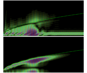
We next analyse the case where the free stream is restricted to vortical waves, again at $F=2.2 \times 10^{-4}$. As investigated by Schrader, Brandt & Henningson (Reference Schrader, Brandt and Henningson2009), there are two competing mechanisms for optimally perturbing the boundary layer using free-stream vortical disturbances: smaller wavelengths (large $\kappa _v$) are able to penetrate deeper into the boundary layer, but suffer faster viscous decay, whereas the opposite is true for larger wavelengths. The optimal distribution of vortical waves, shown in figure 4(a), shows two maxima corresponding to $\kappa _v \approx 0.014$ and $\kappa _v\approx 0.31$. Maximal excitation of disturbances is achieved by simultaneously subjecting the boundary layer to highly penetrating free-stream vortical modes and those that exhibit minimal viscous decay. Near the leading edge, free-stream vorticity penetrates the boundary layer and elicits a non-modal response characterized by large-scale streamwise jets emanating from the wall in the $\hat {u}'$ response field of figure 4(b). These jets are also seen to be modulated by modes F1 and S.

Figure 4. (a) Optimal amplitude profile with free-stream vortical waves at $M_\infty =4.5$ and $F=2.2 \times 10^{-4}$. (b,c) The corresponding $\hat {\boldsymbol {q}}^{s}$ responses (the green isocontour is $\delta _{99}$).

Downstream of the leading edge, the phase speed of mode F1 decreases, and by $x^*\approx 0.11$ m, mode F1 synchronizes with mode S to incite the second mode. During the second-mode growth, however, the streamwise jets remain as seen in figure 4(b). Once the second mode has decayed appreciably by $x^*\approx 0.18$ m, the jets are once again visible, but only weakly and for a short length, as they suffer viscous decay. This is because free-stream vortical disturbances with $\kappa _v\approx 0.31$, which corresponds to $\lambda _v \approx 1.5\delta _{99}$ at the inlet, optimally excite the jets, but also experience relatively large viscous decay.

Similar calculations were performed for slow acoustic waves, for entropic waves and for the gamut of all free-stream waves. The respective gains are summarized in table 2. Firstly, the slow acoustic waves yielded a gain ${\approx }1.9$ times greater than that of the fast acoustic waves, which corroborates the general understanding that slow waves dominate acoustically induced transition onset in adiabatic-wall high-speed boundary layers (MZ3; Balakumar Reference Balakumar2015). Vortical waves yielded a gain nearly identical to $G_{all}^c$, suggesting that transient streamwise jets excited by vortical disturbances is the dominant receptivity mechanism for the current configuration. Entropy waves, on the other hand, play no significant role at these conditions. Lastly, the unconstrained optimization (standard input–output) problem yielded a gain nearly 300 times greater than $G_{all}^c$, suggesting that the physically realizable inputs have a small projection onto the unconstrained (non-physically realizable) inputs. Conversely, a large number of unconstrained forcing modes would be required to represent the physical forcing.

Table 2. Gains from (un)constrained optimizations at $M_\infty =4.5$ and $F=2.2\times 10^{-4}$.

We now compute $G^c$ for the gamut of free-stream disturbances across a range of frequencies. Here, each wave mode (fast/slow acoustic, vortical and entropic) is discretized with $N=1000$ points, but in contrast to § 2.5, half the acoustic waves radiate above ($\kappa _a\leqslant 0$) while the other half radiate below ($\kappa _a\geqslant 0$) the plate. Additionally, $\alpha _a<0$ is included in the fast acoustic ansatz. The gain profile and the maximum amplitude from each wave mode, which reveals the dominant free-stream disturbance type, are shown in figure 5. The first mode is optimally excited at $F_{opt}\approx 0.1\times 10^{-4}$, but the gain rapidly decreases with increasing frequency up until $F\approx 0.7\times 10^{-4}$. Then, for $F > 1.1 \times 10^{-4}$, the second mode becomes the dominant instability and peaks at $F_{opt}\approx 1.4\times 10^{-4}$.

Figure 5. Plot of $G^c$ versus $F$ at $M_\infty =4.5$ with the gamut of free-stream waves with the corresponding maximum amplitude from each wave mode (fast/slow acoustic, vortical and entropic).

Across all frequencies, $|a|_{max}$ for entropic waves is the lowest, closely followed by fast acoustic waves. Although $|a|_{max}$ is attributed to a vortical wave at the lowest frequencies, the relative importance of slow acoustic waves steeply increases from $F \approx 0.05 \times 10^{-4}$ and eventually overtakes vortical waves at $F \approx 0.3 \times 10^{-4}$, before becoming subdominant again by $F \approx 0.9\times 10^{-4}$. The dominance of the vortical wave at high frequencies is likely attributed to the ‘swallowing’ effect (Fedorov & Khokhlov Reference Fedorov and Khokhlov2001) where mode F1 synchronizes with the continuous vorticity branch. The resulting mode F1 waves, as discussed above, maximize the amplification of the second mode. While the fast acoustic waves are closer in wavenumber to mode F1, the vortical waves are apparently more effective because they can simultaneously excite mode F1 (‘swallowing’ effect) and mode S (similar wavenumber).

4. Discussion and future work

We have developed a scattering ansatz to study optimal natural boundary-layer receptivity. The technique can be understood as a generalization of receptivity theory to determine the linear combinations of free-stream disturbances that give rise to the maximal disturbance amplification in the boundary layer. At the same time, it can be considered as a restriction of the forcing field in input–output analysis to a subspace associated with excitation by free-stream disturbances. As compared to many receptivity studies based on local methods, the global approach circumvents the need for asymptotics.

As a first application of the approach, we consider 2-D disturbances to a Mach 4.5 flat-plate boundary layer, for which the forward receptivity problem was previously solved using DNS (MZ2; MZ3). The results validate the approach and reveal optimal disturbance amplification scenarios. When the free stream is restricted to fast acoustic waves, maximal response is achieved by subjecting the boundary layer to acoustic waves with incident angles that optimally excite the second mode, but also, to a lesser extent, mode F1. The receptivity mechanism vastly changes, however, in the case of incident vortical waves, where an optimal combination of highly penetrating and minimally decaying incident waves produces a transient response characterized by large-scale streamwise jets emanating from the wall and modulated by modes F1 and S in the $\hat {u}'$ response field. Finally, the efficiency of our approach was demonstrated by computing the optimal receptivity for the same Mach 4.5 flat-plate boundary layer over a range of frequencies, highlighting where first-mode (low-frequency) and second-mode (high-frequency) instabilities are most receptive to different types of free-stream disturbances. While the configurations considered here are restricted, the methodology can be readily applied to three-dimensional disturbances and more complex geometries, and the scattering ansatz can include sources associated with the shock and shock layer.

Funding

This work was supported by The Boeing Company (CT-BA-GTA-1), ONR (N00014-21-1-2158) and NSERC (PGSD3-532522-2019).

Declaration of interests

The authors report no conflict of interest.

References

REFERENCES

Bae, H.J., Dawson, S.T.M. & McKeon, B.J. 2020 Resolvent-based study of compressibility effects on supersonic turbulent boundary layers. J. Fluid Mech. 883, A29.CrossRefGoogle Scholar
Balakumar, P. 2015 Receptivity of hypersonic boundary layers to acoustic and vortical disturbances (Invited). AIAA Paper 2015-2473.CrossRefGoogle Scholar
Bugeat, B., Chassaing, J.-C., Robinet, J.-C. & Sagaut, P. 2019 3D global optimal forcing and response of the supersonic boundary layer. J. Comput. Phys. 398, 108888.CrossRefGoogle Scholar
Chu, B.-T. 1965 On the energy transfer to small disturbances in fluid flow (Part I). Acta Mechanica 1 (3), 215234.CrossRefGoogle Scholar
Cook, D.A., Knutson, A., Nichols, J.W. & Candler, G.V. 2020 Matrix methods for input–output analysis of 2D and 3D hypersonic flows. AIAA Paper 2020-1820.CrossRefGoogle Scholar
Cook, D.A. & Nichols, J.W. 2022 Free-stream receptivity of a hypersonic blunt cone using input–output analysis and a shock-kinematic boundary condition. Theor. Comput. Fluid Dyn. 36 (1), 155180.CrossRefGoogle Scholar
Crouch, J.D. 1992 Non-localized receptivity of boundary layers. J. Fluid Mech. 244, 567581.CrossRefGoogle Scholar
Duck, P.W., Ruban, A.I. & Zhikharev, C.N. 1996 The generation of Tollmien–Schlichting waves by free-stream turbulence. J. Fluid Mech. 312, 341371.CrossRefGoogle Scholar
Fedorov, A.V. 2003 Receptivity of a high-speed boundary layer to acoustic disturbances. J. Fluid Mech. 491, 101129.CrossRefGoogle Scholar
Fedorov, A.V. & Khokhlov, A.P. 2001 Prehistory of instability in a hypersonic boundary layer. Theor. Comput. Fluid Dyn. 14 (6), 359375.CrossRefGoogle Scholar
Goldstein, M.E. 1983 The evolution of Tollmien–Sclichting waves near a leading edge. J. Fluid Mech. 127, 5981.CrossRefGoogle Scholar
Jeun, J., Nichols, J.W. & Jovanović, M.R. 2016 Input–output analysis of high-speed axisymmetric isothermal jet noise. Phys. Fluids 28 (4), 047101.CrossRefGoogle Scholar
Kamal, O., Rigas, G., Lakebrink, M.T. & Colonius, T. 2021 Input/output analysis of hypersonic boundary layers using the One-Way Navier–Stokes (OWNS) equations. AIAA Paper 2021-2827.CrossRefGoogle Scholar
Lugrin, M., Beneddine, S., Leclercq, C., Garnier, E. & Bur, R. 2021 Transition scenario in hypersonic axisymmetrical compression ramp flow. J. Fluid Mech. 907, A6.CrossRefGoogle Scholar
Ma, Y. & Zhong, X. 2003 a Receptivity of a supersonic boundary layer over a flat plate. Part 1. Wave structures and interactions. J. Fluid Mech. 488, 3178.CrossRefGoogle Scholar
Ma, Y. & Zhong, X. 2003 b Receptivity of a supersonic boundary layer over a flat plate. Part 2. Receptivity to free-stream sound. J. Fluid Mech. 488, 79121.CrossRefGoogle Scholar
Ma, Y. & Zhong, X. 2005 Receptivity of a supersonic boundary layer over a flat plate. Part 3. Effects of different types of free-stream disturbances. J. Fluid Mech. 532, 63109.CrossRefGoogle Scholar
Malik, M.R. 1990 Numerical methods for hypersonic boundary layer stability. J. Comput. Phys. 86 (2), 376413.CrossRefGoogle Scholar
McKenzie, J.F. & Westphal, K.O. 1968 Interaction of linear waves with oblique shock waves. Phys. Fluids 11 (11), 23502362.CrossRefGoogle Scholar
Monokrousos, A., Åkervik, E., Brandt, L. & Henningson, D.S. 2010 Global three-dimensional optimal disturbances in the Blasius boundary-layer flow using time-steppers. J. Fluid Mech. 650, 181214.CrossRefGoogle Scholar
Nichols, J.W. & Candler, G.V. 2019 Input–output analysis of complex hypersonic boundary layers. AIAA Paper 2019-1383.CrossRefGoogle Scholar
Nichols, J.W. & Lele, S.K. 2011 Global modes and transient response of a cold supersonic jet. J. Fluid Mech. 669, 225241.CrossRefGoogle Scholar
Qin, F. & Wu, X. 2016 Response and receptivity of the hypersonic boundary layer past a wedge to free-stream acoustic, vortical and entropy disturbances. J. Fluid Mech. 797, 874915.CrossRefGoogle Scholar
Ruban, A.I., Keshari, S.K. & Kravtsova, M.A. 2021 On boundary-layer receptivity to entropy waves. J. Fluid Mech. 929, A17.CrossRefGoogle Scholar
Schmidt, O.T., Towne, A., Rigas, G., Colonius, T. & Brès, G.A. 2018 Spectral analysis of jet turbulence. J. Fluid Mech. 855, 953982.CrossRefGoogle Scholar
Schrader, L.-U., Brandt, L. & Henningson, D.S. 2009 Receptivity mechanisms in three-dimensional boundary-layer flows. J. Fluid Mech. 618, 209241.CrossRefGoogle Scholar
Skene, C.S., Yeh, C.-A., Schmid, P.J. & Taira, K. 2022 Sparsifying the resolvent forcing mode via gradient-based optimisation. J. Fluid Mech. 944, A52.CrossRefGoogle Scholar
Thompson, K.W. 1987 Time dependent boundary conditions for hyperbolic systems. J. Comput. Phys. 68 (1), 124.CrossRefGoogle Scholar
Towne, A., Rigas, G., Kamal, O., Pickering, E. & Colonius, T. 2022 Efficient global resolvent analysis via the one-way Navier–Stokes equations. J. Fluid Mech. 948, A9.CrossRefGoogle Scholar
Trefethen, L.N., Trefethen, A.E., Reddy, S.C. & Driscoll, T.A. 1993 Hydrodynamic stability without eigenvalues. Science 261 (5121), 578584.CrossRefGoogle ScholarPubMed
Figure 0

Figure 1. A depiction of $\mbox {supp}( {\boldsymbol{\mathsf{L}}}' \hat {\boldsymbol {q}}^{{i}})$: (a) supersonic case generally; and (b) idealized supersonic flat plate without shock layer. The depth of the blue shaded region corresponds to the strength of $\text {supp}({\boldsymbol{\mathsf{L}}}' \hat {\boldsymbol {q}}^{{i}})$, whereas the red dashed lines indicate surface scattering from the body and shock. The grey shaded region in panel (b) corresponds to the computational domain utilized.

Figure 1

Table 1. Summary of relevant DNS performed by MZ1 (Ma & Zhong 2003a), MZ2 (Ma & Zhong 2003b) and MZ3 (Ma & Zhong 2005) of a 2-D Mach 4.5 adiabatic-wall, flat-plate boundary layer.

Figure 2

Figure 2. (a) Wall-pressure amplitudes for the present ${\hat {\boldsymbol {q}}}$ solution compared to those of MZ2 and MZ3 with free-stream slow (SA) and fast (FA) acoustic waves at $M_\infty =4.5$ and $F=2.2 \times 10^{-4}$. (b,c) The corresponding density responses for SA (b) and FA (c).

Figure 3

Figure 3. (a) Optimal amplitude profiles with free-stream fast acoustic waves at $M_\infty =4.5$ and $F=2.2 \times 10^{-4}$. (b,c) The corresponding $\hat {\boldsymbol {q}}^{s}$ responses (the green isocontour is $\delta _{99}$). Coloured lines in panel (a) are the response coefficients from MZ2, the dashed lines are along the optimal angles from the scattering framework, and the dash-dotted line is the optimal amplitude profile with scattering sources restricted to $\delta _{99}$.

Figure 4

Figure 4. (a) Optimal amplitude profile with free-stream vortical waves at $M_\infty =4.5$ and $F=2.2 \times 10^{-4}$. (b,c) The corresponding $\hat {\boldsymbol {q}}^{s}$ responses (the green isocontour is $\delta _{99}$).

Figure 5

Table 2. Gains from (un)constrained optimizations at $M_\infty =4.5$ and $F=2.2\times 10^{-4}$.

Figure 6

Figure 5. Plot of $G^c$ versus $F$ at $M_\infty =4.5$ with the gamut of free-stream waves with the corresponding maximum amplitude from each wave mode (fast/slow acoustic, vortical and entropic).