Hostname: page-component-586b7cd67f-rdxmf Total loading time: 0 Render date: 2024-11-22T21:52:36.096Z Has data issue: false hasContentIssue false

Gas-dynamic and mixing analysis of under-expanded hydrogen jets: effect of the cross section shape

Published online by Cambridge University Press:  29 August 2023
Giuseppe Anaclerio*
Affiliation:
Department of Mechanics, Mathematics and Management, Polytechnic University of Bari, Bari 70125, Italy
Tommaso Capurso
Affiliation:
Arts et Metiers Institute of Technology, LIFSE, CNAM, HESAM University, Paris 75013, France
Marco Torresi
Affiliation:
Department of Mechanics, Mathematics and Management, Polytechnic University of Bari, Bari 70125, Italy
*
Email address for correspondence: [email protected]

Abstract

Green hydrogen is expected to have a key role in the transition towards a carbon-neutral society, particularly in the transportation sector. Exploration of novel solutions for the direct injection of hydrogen in internal combustion engines (ICEs) is a main topic for both academia and industry. Here, the authors explore the gas-dynamic and mixing features of hydrogen under-expanded jets exiting from non-axisymmetric cross-sections, with the aim to provide guidelines for designing novel generations of ICE hydrogen injectors. Triangular and star shapes have been compared with elliptical and rectangular sections with different aspect ratios. Differences in the shock wave systems are reported, and explanations of the gas-dynamic mechanisms developed by each section are proposed. Non-uniformity in the radial expansion of the jet boundary has been noticed in all of the non-axisymmetric sections, leading to an axis switching of the jet in some cases. Differences in the radial mixing and axial jet penetration have been reported too, and a robust correlation with the vorticity distribution along the jet boundary has been observed.

Type
JFM Papers
Copyright
© The Author(s), 2023. Published by Cambridge University Press

1. Introduction

According to the International Energy Agency (IEA), renewable sources are expected to play a key role in the current energy transition scenario, as they will become the main source of electricity generation by 2025 (IEA 2020). Through the power-to-gas technology (Gahleitner Reference Gahleitner2013), an ever-increasing amount of green hydrogen is expected to be available in the near future. Green hydrogen will then have a central role in powering turbines, fuel cells and internal combustion engines (ICEs) (Capurso et al. Reference Capurso, Stefanizzi, Torresi and Camporeale2022). Regarding ICEs fuelled with hydrogen, the mixture formation inside the cylinder is a crucial aspect. Both academia and industry are concerned in developing novel solutions for a quicker homogenization of the charge. The direct injection (DI) of H$_2$ into the engine cylinder leads to the onset of under-expanded jets whose features affect the mixing process in the chamber (Wimmer et al. Reference Wimmer, Wallner, Ringler and Gerbig2005; Yamane Reference Yamane2018; Yip et al. Reference Yip, Srna, Yuen, Kook, Taylor, Yeoh, Medwell and Chan2019).

Under-expanded jets have been thoroughly investigated in the literature, as reported in the review by Franquet et al. (Reference Franquet, Perrier, Gibout and Bruel2015). Most of the research has focused on jets issuing from convergent and convergent–divergent ducts with circular cross-sections (Adamson & Nicholls Reference Adamson and Nicholls1959; Love et al. Reference Love, Grisby, Lee and Woodling1959; Crist, Glass & Sherman Reference Crist, Glass and Sherman1966; Velikorodny & Kudriakov Reference Velikorodny and Kudriakov2012), at different nozzle pressure ratios (NPRs) (Boynton Reference Boynton1967; Abbett Reference Abbett1971). For NPRs greater than 4, the onset of one or more strong normal shocks, the so-called Mach disks, has been deeply analysed. Position (Ashkenas & Sherman Reference Ashkenas and Sherman1964; Lewis & Carlson Reference Lewis and Carlson1964), diameter (Addy Reference Addy1981; Hatanaka & Saito Reference Hatanaka and Saito2012) and hysteretic behaviour (Gribben, Badcock & Richards Reference Gribben, Badcock and Richards2000; Irie et al. Reference Irie, Yasunobu, Kashimura and Setoguchi2003; Otobe et al. Reference Otobe, Yasunobu, Kashimura, Matsuo, Setoguchi and Kim2009) are among the main features that have been examined. Conversely, the influence of the nozzle cross-section shape has received less attention by the researchers. The available works are generally focused on elliptical and rectangular sections.

Rajakuperan & Ramaswamy (Reference Rajakuperan and Ramaswamy1977) numerically solved the under-expanded structure of elliptical jets, showing different shock patterns along the minor and major axis planes. A quicker growth of the boundary along the minor axis of the section was noted, ultimately leading downstream to the inversion of the axes (axis switching phenomenon). Menon & Skews (Reference Menon and Skews2005) analysed elliptical nozzles with aspect ratios (ARs) equal to 2 and 4 and pressure ratios from 4 to 6. They observed different dimensions of the Mach disk along the minor and major cross-section axes, which confirmed the axis switching of the jet observed by Rajakuperan. The axis switching was generically attributed to the different curvature of the exit section in the minor and major axes. Menon & Skews (Reference Menon and Skews2010) also observed that the barrel shock originates just after the nozzle exit section in the major axis plane, and later along the minor axis plane. Such a trend was further intensified for the higher ARs. This behaviour was generically attributed to the variable curvature of the elliptical section, but a clear mechanism for the quicker onset of the barrel shock along the major axis plane was not provided. Chauhan, Kumar & Rathakrishnan (Reference Chauhan, Kumar and Rathakrishnan2016) analysed different elliptical jets with ARs of 2, 4 and 6 and pressure ratios from 2 to 5, comparing results with a circular nozzle of the same area. They found superior levels of mixing for all the tested NPRs. Interestingly, the influence of the AR on the mixing level seemed to be dependent on the under-expansion intensity. At the lower NPRs, jets released from a section of ARs 4 and 6 featured a superior level of mixing, whereas a more intense mixing was promoted by the AR 2 nozzle at the higher NPRs. They attributed the higher mixing of the elliptical sections to the generation of eddies of different size (smaller in the major axis plane, greater in the minor) that enhance the different scales of the turbulent mixing. The same conclusions were drawn by Kumar & Rathakrishnan (Reference Kumar and Rathakrishnan2016) to explain the higher mixing provided by an AR 2 over-expanded elliptical jet issuing at Mach 2.

As reported in the literature, rectangular jets provide an enhanced mixing as well, mainly due to the higher level of turbulence generated by the shape (Makarov & Molkov Reference Makarov and Molkov2013). Teshima (Reference Teshima1994) experimentally analysed rectangular under-expanded jets for different ARs (2, 3, 4, 5, 62) and NPRs up to 500 using the laser induced fluorescence technique. Attention was paid to the transition from the regular to the Mach reflection of the incident shock waves. He noted that the Mach transition did not depend solely on the NPR but an influence of the inlet total pressure was observed. No detailed description of the shock system was provided. Computational studies have been carried out by Pao & Abdol-Hamid (Reference Pao and Abdol-Hamid1996), who reported a quicker growth of the boundary along the minor axis of the exit section similarly to the elliptical cases, and the rounding of the corners due to the turbulent mixing. For square sections, a 45$^\circ$ rotation of the jet boundary was also noticed. Menon & Skews (Reference Menon and Skews2010) used the laser vapour screen visualization technique to get ‘slices’ of the flow field of under-expanded jets discharged by rectangular and square nozzles for pressure ratios of 4 and 6. To the authors’ knowledge, he was the first to provide a detailed explanation of the near-field structure of such jets. Differently from circular nozzles, over-expanded conditions were recognized close to the corners of the outlet section, which caused the onset of four re-compression shock waves but did not performed any consideration regarding the effects of the Mach disk features. Along the radial direction, saddle shape profiles in the velocity and mass distributions were also observed. To the authors’ knowledge, these profiles have been mostly investigated in subsonic flows (see Trentacoste & Sforza Reference Trentacoste and Sforza1967; Sfeir Reference Sfeir1976). Krothapalli, Baganoff & Karamcheti (Reference Krothapalli, Baganoff and Karamcheti1981) and Zaman (Reference Zaman1996) attributed the saddle-shaped profile to the development of three-dimensional (3-D) vortex rings shed from the nozzle lips, in synergy with the streamwise vorticity of the secondary flows developed inside the nozzle.

In this paper, authors have analysed the gas-dynamic and mixing features of hydrogen under-expanded jets released by elliptical and rectangular jets. As much of the current research focuses on H$_2$ DI in ICEs, the authors have considered a convergent duct with the typical size of an automotive injector. Differently from most of the literature, we have analysed jets under a NPR of 10, which corresponds to a highly under-expanded condition. Indeed, H$_2$ DI feed pressure is expected to increase in the near future. Results observed in the rectangular cases have prompted the authors to further analyse a triangular-shaped section and a star one, which have been considered a way to deepen the gas-dynamic flow features developed by sections characterized by convex and concave angles. To such a purpose, 3-D Reynolds-averaged Navier–Stokes (RANS) simulations have been carried out, since the shock system development is mainly an inviscid phenomenon that does not require more advanced approaches (large-eddy simulations (LES), direct numerical simulations). Regarding the mixing analysis, although the LES simulations would provide closer results to the experiments (see Wang & McGuirk Reference Wang and McGuirk2013) than RANS, the latter are still reliable when one wants to perform analyses on a large number of cases. Numerical Schlieren pictures provide insights of the shock waves development along the characteristic planes of the jets. For the rectangular and elliptical sections, the dependence of the Mach disk position on the AR is described, together with an explanation of the observed shift toward the nozzle exit section. Such information can be useful in safety applications: in the Mach disk notional nozzle approach – a tool for quick simulations restricted to the far-field region – the knowledge of the Mach disk position is information required a priori (Harstad & Bellan Reference Harstad and Bellan2006; Winters & Evans Reference Winters and Evans2007). Moreover, differences in the nature of the shock system have been observed between the lower and higher AR elliptical jets. The jet boundary development and the H$_2$ distributions are reported as well, highlighting the dependence on the vorticity field settled around the jet. The vorticity distribution results are found to be well related to the intensity of the mixing and ultimately drives the deformation of the jet boundary.

2. Case study

In figure 1 a sketch of the computational domain is shown. It is basically made up of three zones: a cylindrical body (green) with a sufficiently large diameter to minimize the total pressure losses, a convergent nozzle ending with a constant section duct and a cylindrical discharging ambient with large dimensions to avoid confinement effects. Such a configuration creates a radial velocity field in the convergent section, which tends to zero in the constant section duct. Hence, flow can be considered axial at the outlet section. For a generic cross-section shape, $D_{nozzle,eq}$ has been defined as the diameter of the circular section with the same area. The length of the discharging chamber has been set equal to 35$D_{nozzle,eq}$. The position of the Mach disk is expected to be around 2$D_{nozzle,eq}$ and the length of the potential core about 26$D_{nozzle,eq}$ (see Franquet et al. Reference Franquet, Perrier, Gibout and Bruel2015). Consequently, the length of the discharging chamber has been deemed sufficient to solve the near-field zone of the jet. The diameter of the chamber has been set to 14$D_{nozzle,eq}$, enough to avoid the interaction with the boundary condition along the lateral surface. The convergent nozzle has been preferred to convergent–divergent configurations in order to analyse flows at sonic condition (Mach equal to 1) in the exit section. Moreover, a geometrical configuration of this kind can be considered an acceptable approximation of DI gaseous injectors for ICE applications (Yip et al. Reference Yip, Srna, Yuen, Kook, Taylor, Yeoh, Medwell and Chan2019).

Figure 1. Section of the numerical domain used in this work with the boundary conditions applied to the domain boundaries. On the right is a detailed view of the nozzle exit.

The choice of the cross-section area is coherent with benchmark experiments on H$_2$ DI ICE. All the nozzles have the same outlet area of 1.67 mm$^2$, which is the exit area of the circular injector equipping the H$_2$ optical engine tested at the Sandia National Laboratories (Wallner et al. Reference Wallner, Matthias, Scarcelli and Kwon2013). Sketches of the sections are reported in figure 2. For the rectangular and elliptical sections, ARs (defined as the ratio between the major, A, to minor, B, sides for the rectangular section, and between the major to the minor axes for the elliptical one) equal to 1.5, 5.0 and 8.0 have been taken into account. The AR 8.0 has been selected on the basis of manufacturing considerations: for the chosen outlet area, an elliptical section featuring an even higher AR would result in an excessive curvature along the minor axis plane. The minimum AR has been chosen to be close to one, while the AR 5 has been selected as a middle value between the maximum and minimum ARs. The triangular section is equilateral, while the star is composed of an inner central square sharing sides with four equilateral triangles. By examining this set of shapes, insights regarding the influence of constant curvature (circular section), continuously varying curvature (elliptical section), convex and concave angles (rectangular, triangular and star section) can be obtained.

Figure 2. Sketch of the nozzle section shapes analysed in this work. Here L, S, A and B indicate the dimensions of the different cross-sections; AR is the aspect ratio.

3. Numerical model and validation

In figure 3 a cut plane of the mesh employed in this work is reported, along with an enlargement downstream of the nozzle exit section. The mesh is made up of tetrahedral elements, which is a useful feature at such a stage of the study, in which no information about the orientation of the main eddies is available. Two levels of refinement can be observed in the enlargement. A mean cell size of 50 $\mathrm {\mu }$m has been applied in the near-field zone of the jet, where intense gas-dynamic phenomena are expected to occur. Externally to the near-field zone, an average cell size of 100 $\mathrm {\mu }$m has been deemed sufficient to effectively capture the mixing layer of the jet, responsible for the diffusion of the H$_2$ into the ambient fluid (see Anaclerio et al. Reference Anaclerio, Capurso, Torresi and Camporeale2023). The general physics behaviour of the flow is described by the following mass, momentum and energy equations:

(3.1)\begin{align} \left.\begin{array}{c@{}} \displaystyle{\dfrac{\partial \rho}{\partial t}} + \boldsymbol{\nabla}\boldsymbol{\cdot}(\rho\boldsymbol{v})= 0,\\ \displaystyle{\dfrac{\partial(\rho \boldsymbol{v})}{\partial t}} + \boldsymbol{\nabla}\boldsymbol{\cdot}(\rho \boldsymbol{v}\boldsymbol{v}) =-\boldsymbol{\nabla} p + \boldsymbol{\nabla} \boldsymbol{\cdot} \boldsymbol{\tau} + \rho \boldsymbol{f},\\ \displaystyle{\dfrac{\partial}{\partial t}}\left(\rho \left(e+\dfrac{v^2}{2}\right)\right) + \boldsymbol{\nabla}\boldsymbol{\cdot}\left(\rho \boldsymbol{v}\left(h+\dfrac{v^2}{2}\right)\right) = \boldsymbol{\nabla} \boldsymbol{\cdot} \left(k \boldsymbol{\nabla} T - \sum_{i}h_i\boldsymbol{J_i} + \boldsymbol{\tau} \boldsymbol{\cdot} \boldsymbol{v}\right). \end{array}\right\} \end{align}

Here $\rho$ is the local flow density, $\boldsymbol {v}$ the velocity vector, $p$ the static pressure, $\boldsymbol {\tau }$ the deviatoric stress tensor, $\boldsymbol {f}$ the mass forces vector, $e$ the internal energy, $h$ the enthalpy, $k$ the thermal conductivity, $T$ the temperature, $h_i$ the enthalpy of the $i$th species and $J_i$ the diffusion flux of the $i$th species (see (3.5)). In this work the steady form of the conservation equations has been solved. Indeed, as previously verified by the authors (see Anaclerio et al. Reference Anaclerio, Capurso, Torresi and Camporeale2023), the characteristic variation of the NPR during the injection in ICE applications is too small to produce hysteretic effects. Therefore, features of the shock system can be analysed by means of a steady computation. The coupled pressure-based algorithm has been used to solve the conservation equations. In the pressure-based solvers, the mass conservation equation is replaced by a pressure-corrected continuity equation, in such a way that the velocity field satisfies the continuity. In the coupled formulation the momentum and pressure-corrected continuity equations are solved simultaneously. Energy, turbulence and all of the other transport equations are solved successively. Even though the pressure-based formulation has been conceived for incompressible flows, its applicability has been extended to compressible regimes too (see Denner Reference Denner2018). Moreover, because of the coupling between the momentum equation and pressure-corrected continuity, the coupled scheme is closest to the density-based solver. The mixture has been modelled as a real gas, using the Redlich–Kwong equation of state (EoS). According to Bonelli, Viggiano & Magi (Reference Bonelli, Viggiano and Magi2013), this model is suitable for hydrogen numerical computations, because of the ability to closely match the experimental data of the National Institute of Standards and Technology in terms of compressibility factor. When comparing the ideal-gas model with the real-gas models for a high pressure injection (750 bar), Bonelli observed a higher intensity of the Mach disk shock when using the real-gas models. The same conclusion has been drawn by the authors for a 10 bar injection in a previous work (see Anaclerio et al. Reference Anaclerio, Capurso, Torresi and Camporeale2023) and, thus, the Redlich–Kwong EoS has been here adopted. The Redlich–Kwong EoS is one of the cubic EoS available in ANSYS Fluent®, whose general form is

(3.2)\begin{equation} p = \frac{RT}{v-b+c}-\frac{a}{v^{2}+v{\delta}+{\epsilon}}, \end{equation}

where $a$, $b$, $c$, $\delta$ and $\epsilon$ are parameters related to the fluid critical pressure and critical temperature ($p_{c}$, $T_{c}$), to the acentric factor $\omega$ and specific volume $v$. The acentric factor $\omega$ is defined as $\omega = -\log _{10}(\,{p_{sat}}/{p_{c}})$, where the saturation pressure $p_{sat}$ is evaluated for $T = 0.7T_c$. It is a measure of the non-sphericity of molecules, and influences the boiling point of the species. ANSYS Fluent® computes the generic critical constant $C_{cm}$ of the mixture (i.e. the critical pressure and critical temperature of the mixture) on the basis of the mass fractions $x_i$ and critical constants $C_{ci}$ of each ith component (i.e. the critical pressure and critical temperature of each component in the mixture) as

(3.3)\begin{equation} C_{cm} = \sum_{i=1}^N x_{i}C_{ci}. \end{equation}

In addition to the conservation of mass, momentum and energy, the injection process for a mixture of $N$ chemical species is captured by solving $N - 1$ transport equations in the form

(3.4)\begin{equation} \frac{\partial \rho Y_i}{\partial t} + \boldsymbol{\nabla}\boldsymbol{\cdot}{(\rho \boldsymbol{v} Y_{i})} =-\boldsymbol{\nabla}\boldsymbol{\cdot}{\boldsymbol{J_{i}}} + R_{i} + S_{i}, \end{equation}

where $\rho$ and $\boldsymbol {v}$ are the local density and velocity, $Y_{i}$ is the mass fraction for the ith species, $R_{i}$ is the rate of production by chemical reactions and $S_{i}$ is a user-defined source term. Here $\boldsymbol {J_{i}}$ is the diffusion flux of the ith species due to concentration and thermal gradients. For turbulent flows, it is computed as

(3.5)\begin{equation} \boldsymbol{J_{i}} =-\left(\rho D_{i,m} + \frac{\mu_{t}}{Sc_{t}}\right)\boldsymbol{\nabla} Y_{i}-D_{T,i}\frac{\boldsymbol{\nabla} T}{T}, \end{equation}

where $D_{i,m}$ is the mass diffusion coefficient, $\mu _{t}$ the turbulent viscosity, $Sc_{t}$ the turbulent Schmidt number and $D_{T,i}$ the thermal diffusion coefficient of the ith species, accounting for the Soret effect. To better estimate the diffusion of the chemical species, the kinetic theory model provided by ANSYS Fluent® has been exploited to compute the mass diffusion coefficient $D_{i,m}$. The nth species is computed by difference, since $\sum _{i=1}^N Y_i = 1$ must hold. At the inlet of the domain, a flow of pure hydrogen has been applied by setting the H$_2$ mass fraction to 1. Total conditions of 10 bar and 300 K have been imposed too. Both the right face and the lateral surfaces of the discharging cylinder have been treated as pressure outlet boundaries (see figure 1), setting a static pressure equal to 1 bar. To reduce the computational time, water vapour in the air has not been taken into account, thus solving transport equations only for H$_2$ and O$_2$. This choice is reasonable since the volume fraction of water vapour in both pressurized hydrogen and ambient air is negligible. For the aforementioned boundary conditions, the NPR results equal 10; hence, extremely under-expanded conditions are expected to be achieved. Therefore, significant variations of the temperature inside the jet are expected, leading to the adoption of the three parameters Sutherland law to model the local viscosity. Spatial derivatives have been discretized by means of a second-order accurate upwind scheme. Several studies are present in the literature to assess the most suitable turbulence model for RANS equations closure. According to Senesh & Babu (Reference Senesh and Babu2012), for round compressible jets, the Spalart–Allmaras model over-predicts the axial velocity decay rate and under-predicts the potential core length (i.e. the near-field zone where the gas-dynamic effects are predominant). The re-normalisation group (RNG) $k$-$\varepsilon$ better captures the potential core length, but the axial decay rate is again over-predicted. The standard $k$-$\varepsilon$ computes an axial decay rate slightly slower than the RNG model, but under-predicts the potential core length. Tide & Babu (Reference Tide and Babu2008) compared the Wilcox $k$-$\omega$ model against the shear stress transport (SST) $k$-$\omega$ using a jet at Mach number 0.9 as a benchmark. Both the models showed acceptable agreement with the experimental data, but the SST $k$-$\omega$ was found to be less sensitive to the mesh density, which is a favourable characteristic to exploit when 3-D simulations have to be carried out. To define the most suitable turbulence model, and to test the validity of the set-up previously described, a validation step has been deemed necessary. Two benchmarks have been carried out. In the first one, the experimental data provided by Ruggles & Ekoto (Reference Ruggles and Ekoto2014) have been exploited to assess the validity of the numerical results in terms of H$_{2}$ axial penetration. In this case, a rectangular nozzle ($\textrm {AR}=8$) has been tested applying a NPR equal to 10. In figure 4 the reciprocal of the H$_{2}$ axial mass fraction has been plotted against the non-dimensional axial position (being $r_{eq}$ the radius of the circular area with the same area). The $k$-$\varepsilon$, SST $k$-$\omega$ and Reynolds stress model (RSM) closures have been examined using the default configurations set by ANSYS Fluent®. As it can be observed, the SST $k$-$\omega$ provides the closest outcomes to the experimental data, and consequently, it has been chosen for the RANS closure. As a secondary step, the ability to capture the gas-dynamic features of the under-expanded jets has been analysed. In particular, a circular nozzle of 1 mm diameter under a NPR of 10 has been taken into account. As can be seen in the experimental Schlieren picture reported in figure 5 (see Hecht, Li & Ekoto Reference Hecht, Li and Ekoto2015), the Mach disk is located at about 2 mm from the nozzle exit section, which is coherent with the theoretical position computed by the following correlation (see Franquet et al. Reference Franquet, Perrier, Gibout and Bruel2015):

(3.6)\begin{equation} \frac{H_{disk}}{D_{nozzle}} = 0.63\sqrt{{\rm NPR}}. \end{equation}

Here $H_{disk}$ is the Mach disk position and $D_{nozzle}$ the nozzle exit diameter. In this case $H_{disk} = 1.99$ mm. As reported in table 1, the numerical position of the shock is correctly captured by the simulations. The cell size of 50 $\mathrm {\mu }$m in the near-field zone of the jet has been considered a good compromise between the accuracy of the results and the required computational time. Hence, this level of refinement and the discussed numerical set-up have been considered suitable for the further studies proposed in this work.

Figure 3. (a) Representation of the numerical grid on a section plane. (b) Detail of the mesh refinement on two boxes downstream of the nozzle exit section.

Figure 4. Comparison between the experimental (Ruggles & Ekoto Reference Ruggles and Ekoto2014) and numerical results of the reciprocal H$_2$ mass fraction ($Y_{H_2}$) along the axial direction ($z$) for an AR 8.0 rectangular jet, $\textrm {NPR} = 10$.

Figure 5. (a) Experimental Schlieren provided by Hecht et al. (Reference Hecht, Li and Ekoto2015). (b) Numerical Schlieren computed with a near-field cell size of 10 $\mathrm {\mu }$m.

Table 1. Mesh sensitivity analysis. Comparison of the Mach disk position for different grid refinements.

4. Results

4.1. Influence of the section shape

Comparisons among the different shapes have been performed applying identical total conditions at the inlet, in order to have the same choked mass flow rate. The Reynolds number, computed choosing $D_{nozzle,eq}$ as a reference length, is equal to $1.1\times 10^5$ at the outlet section. In figure 6 the longitudinal numerical Schlieren of the jet issuing from the circular section nozzle is shown. The distinctive features widely described in the literature are visible. An expansion fan occurs at the nozzle exit (the white v-shaped area starting at the nozzle exit section), due to the pressure difference between the exit section and the surrounding ambient. The weak waves of the fan reflect at the jet boundary and turn into compression waves, whose coalescence leads to the formation of the barrel shock. This feature begins to be visible slightly downstream of the exit section and is characterized by a convergent shape. At $\textrm {NPR}=10$ the regular reflection of the barrel shock at the axis is no longer possible. Hence, a Mach disk normal to the flow is formed. In figure 6 it appears to have a negligible curvature, conversely to other cases shown in the following. The Mach reflection is completed by the formation of a reflected shock emanating from the point shared by the Mach disk and the barrel shock. Flow just downstream of the Mach disk is subsonic, while it is still supersonic after passing through the reflected shock. As a consequence, a shear layer is needed to divide the two flows. It appears to be convergent, resulting in a subsequent flow acceleration after the Mach disk (see figure 7), which is however not sufficient to repeat the pattern.

Figure 6. Numerical Schlieren picture of the under-expanded jet obtained from the circular section, $\textrm {NPR} = 10$, $T_0 = 300$ K, on a longitudinal section plane.

Figure 7. Mach number along the axis of the circular jet, $\textrm {NPR} = 10$.

The above-mentioned flow pattern is perfectly axisymmetric and easy to describe. Moreover, it is characterized by an axisymmetric H$_2$ penetration and distribution along either the radial and axial directions. Significant differences from the classical shock-expansion structure of circular jets have been observed in the non-circular sections.

4.1.1. Triangular section

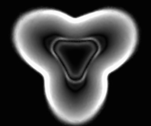
The equilateral triangular section has been selected to investigate the influence of acute angles on the shock-expansion system. In figure 8 the longitudinal Schlieren pictures are reported. Here, some major differences with respect to the classical circular nozzle are present. As it can be observed along the symmetry plane in figure 8(a), the barrel shock forms almost immediately from the upper vertex, while the onset is delayed from the edge of the triangle. The reasons behind the shock formation are indeed quite different. At the vertex (convex zone), the interaction between the fans originating from two consecutive sides leads to a locally over-expanded flow: pressure drops below the ambient pressure, and consequently, a shock wave quickly forms to re-compress the flow. The over-expanded condition is visible in figure 9(a), reporting the static pressure contours at the exit section of the nozzle: while the static pressure is equal to 284 000 Pa along the edges, a minimum of about 70 000 Pa is reached at the corners, which is below the ambient pressure of 100 000 Pa. The re-compression shock wave is the barrel shock visible in figure 8(a). At the basis, the classical formation of the barrel shock takes place. However, coalescence of the expansion waves is quicker for higher curvatures (i.e. for smaller radii of the osculating circles): in this case, the edge curvature equal to zero leads to a very delayed formation of the barrel shock. Such a trend is visible in figure 8(b), in which the shock-expansion system is symmetrical. To clarify the structure of the shock system, the shock detection method proposed by Lovely and Haimes (see Lovely & Haimes Reference Lovely and Haimes1999) has been exploited to produce figure 9(b). Here, the three corner shocks are clearly visible. They result to point towards the axis, eventually reflecting and forming a Mach disk normal to the axis, followed by a reflected shock. In figure 10 the numerical Schlieren pictures relative to five planes normal to the axis are shown to further draw insights of the shock system. At 0.5 mm from the nozzle exit, it can be observed that the over-expansion condition leads to the onset of the corner shock waves. Moving further downstream, the shock waves become wider (see figure 10b,c) and eventually reflect (figure 10d). In this specific case, the reflection is irregular; hence, a lateral Mach disk and the related reflected waves form. The incident shock system is then made up of the three corner shocks, their Mach disks and the lateral reflected waves. The incident shock system points towards the jet axis, causing the onset of a strong normal Mach disk. After this, the shear layer and the reflected shock propagate downstream (both shown in figure 10(e)). Another distinctive feature observable in the Schlieren pictures is the growth of the jet boundary. The boundary expands faster from the centre of the edges and slower from the vertices, resulting in a deformation that leads to a three-lobe jet. This behaviour is related to the higher level of the vorticity magnitude (i.e. the vorticity module) at the centre of the edges. In figure 11(a) the vorticity magnitude distribution along the jet perimeter immediately downstream of the exit section is superimposed to the jet boundary of figure 10(e). As can be observed, the higher vorticity leads to a faster deformation of the boundary from the middle of the sides, ultimately generating the three-lobe shape observed at 3.2 mm from the exit section. Thus, the high vorticity magnitude zones behave as traction points governing the deformation of the boundary. In figure 11(b) the velocity magnitude is shown immediately downstream of the exit section. Higher velocities are found along the jet boundary, because the flow, ejected in the proximity of the wall, meets the expansion fan earlier with respect to the flow released from the inner section. As the velocity module must be unique at the centre of the shape, higher velocity gradients are expected where the distance between the shape centre and the triangle side is minimum (see figure 11b). This can be considered the reason why a higher vorticity module has been observed in the middle of the side edges.

Figure 8. Longitudinal numerical Schlieren picture of the under-expanded jet from the triangular section: (a) in the symmetry plane, and (b) in a plane parallel to the triangle base passing for the centre of the triangle.

Figure 9. (a) Contours of the static pressure at the nominal exit section of the triangular nozzle, and (b) 3-D shock structure of the jet by means of the shock detection method proposed by Lovely & Haimes (Reference Lovely and Haimes1999).

Figure 10. Normal numerical Schlieren pictures of the jet issuing from the triangular section on five different planes normal to the jet axis: at (a) 0.5 mm, (b) 1.0 mm, (c) 1.5 mm, (d) 2.7 mm and at (e) 3.2 mm from the exit section.

Figure 11. (a) Vorticity magnitude contours at the triangular nozzle exit section superimposed to the jet boundary developed further downstream. The high vorticity zones behave as traction points, driving the deformation of the boundary. (b) Velocity magnitude immediately downstream of the exit section: higher velocity is observed along the perimeter due to the earlier expansion of the outer flow.

4.1.2. Star-shaped section

The triangular section has a convex shape. Consequently, it has been deemed interesting to analyse the jet structure developed by a nozzle section with convex and concave features: the star-shaped section. This shape has eight vertices: four equal to 60$^\circ$ and four equal to 210$^\circ$, alternatively arranged. Figure 12(a) reports the numerical Schlieren along a plane passing through two opposite convex vertices. As already observed in the triangular nozzle, the onset of shock waves just downstream of the exit section is found. Conversely, in the plane passing through two opposite concave vertices, see figure 12(b), the occurrence of the barrel shock is delayed. As already discussed for the triangular section, the onset of the shock waves emanating from the convex vertices is due to the over-expanded condition occurring when the angle is acute, as shown in the pressure contours reported in figure 13(a). In the same picture, it can be observed that concave vertices (obtuse angles) are not subject to the over-expanded condition, since the expansion fans do not cross in the proximity of concave vertices. The 3-D shock system is reported in figure 13(b), where it can be observed that the re-compression corner shocks reflect along the axis forming a normal Mach disk, followed by its reflected shock. Schlieren pictures normal to the jet axis are reported in figure 14. At the exit section the jet holds the same shape of the nozzle. At 0.7 mm, the corner shock waves propagating from the convex vertices are visible. Further downstream, they expand (1.4 mm) and reflect each against the other in an irregular way (note, in the picture at 2.1 mm, the formation of the lateral Mach disks and reflected shocks). At 2.8 mm the Mach disk normal to the jet axis has already formed, and consequently, the shear layer and the reflected shocks can be observed. Regarding the jet boundary, it can be noted that the growth is faster along the diagonals of the inner square with respect to the tip vertices of the triangles. This behaviour can be justified observing the vorticity contours immediately downstream of the nominal exit section (figure 15): the higher values are found at the concave vertices, where the enhanced turbulent diffusion leads to a much quicker growth of the boundary along the diagonals of the square. Thus, as already discussed for the triangular case, zones characterized by a higher vorticity magnitude behave as traction points, more quickly stretching the jet boundary towards the surrounding ambient. Such zones are once again the closest points to the shape centre, confirming that greater vorticity levels are due to the higher velocity gradients.

Figure 12. Longitudinal numerical Schlieren picture of the under-expanded jet from the star nozzle: (a) in a plane passing through the vertices of the triangles, and (b) in a plane along the diagonal of the inner square.

Figure 13. (a) Contours of static pressure at the exit section of the star shaped nozzle and (b) 3-D visualization of the shock system developed by the star nozzle, reconstructed by means of the shock detection method proposed by Lovely & Haimes (Reference Lovely and Haimes1999).

Figure 14. Normal numerical Schlieren pictures of the jet issuing from the star section on five different planes normal to the jet axis: (a) at the nozzle exit, and at (b) 0.7 mm, (c) 1.4 mm, (d) 2.1 mm and (e) 2.8 mm from the exit section.

Figure 15. Vorticity magnitude contours at the star nozzle exit section superimposed to the jet boundary developed further downstream. Also in this case the high vorticity zones behave as traction points, driving the deformation of the boundary.

4.1.3. Elliptical section

In figure 16 the numerical Schlieren pictures are reported for a jet issuing from the AR 1.5 elliptical nozzle. It can be observed that the occurrence of the barrel shock is quicker along the major axis plane, whereas it has a lower intensity along the minor axis plane. This behaviour can be explained looking at figure 17, which reports a sketch of the leading waves of the fans originating at the endpoints of the major and minor axes. Since the pressure $\bar p$ just after the expansion fans at the axis location must be unique, the inclination of the fan from the major axis must be lower (i.e. $\alpha <\theta$ in figure 17). As a consequence, reflection of the expansion waves and coalescence of the compression ones is quicker along the major axis plane, resulting in an earlier formation of barrel shock. Hence, it can be concluded that the coalescence is faster for higher curvatures, and vice versa. What has been described is confirmed by both the 3-D shock system in figure 18 and the normal Schlieren reported in figure 19. At 0.7 mm from the nozzle exit, the incident barrel shock is only visible at the extremes of the major axis, whereas it begins to be observable along the minor axis at 2.1 mm from the exit section. At the imposed NPR of 10, the incident shock system reflects in an irregular way, forming a normal Mach disk followed by its shear layer and the reflected shock, both visible at 3.5 mm downstream of the exit section. In the sequence reported in figure 19, the axis switching phenomenon can be observed: the boundary expands faster along the minor axis plane as an effect of the higher level of the vorticity magnitude (whose distribution has not been reported for the sake of brevity).

Figure 16. Longitudinal numerical Schlieren pictures of the jet issuing from the elliptical nozzle with $\textrm {AR} = 1.5$: (a) major axis plane and (b) minor axis plane.

Figure 17. Sketch of the expansion fans leading waves emanating from the major and minor axes of the elliptical section. Here $\alpha$ and $\theta$ represent the wave inclination from the major and minor axes, whereas $\bar p$ stands for the pressure level at the axis just after the fans.

Figure 18. Shock system developed by the elliptical section, reconstructed by means of the shock detection method proposed by Lovely & Haimes (Reference Lovely and Haimes1999).

Figure 19. Normal numerical Schlieren pictures of the jet issuing from the elliptical nozzle with $\textrm {AR} = 1.5$, on three different planes normal to the jet axis: at (a) 0.7 mm, (b) 2.1 mm and (c) 3.5 mm from the exit section.

4.1.4. Rectangular section

The shock system developed by a rectangular nozzle of AR 1.5 is reported in the longitudinal planes in figure 20. Also in this case, the barrel shock forms earlier along the major axis plane, resulting in the barrel shock being more intense in the major axis plane and less intense in the minor axis plane. Differently from the elliptical case previously analysed, such a trend cannot be justified by different curvatures along the section perimeter. What has been observed can be explained by looking at figure 21, which reports the static pressure contours at the nozzle exit section along with the 3-D shock system, and figure 22, which shows the normal Schlieren pictures. Similarly to the triangular and star-shaped sections, the coexistence of the expansion fans at the vertices of the exit section leads to an over-expanded condition. As a consequence, four re-compression shock waves occur at the vertices, as visible in figures 21(b) and 22(a). At 2.1 mm from the exit section, the re-compression waves have met along the major axis plane, resulting in the barrel shock visible in figure 20(a). Along the minor axis plane, the barrel shock is still not visible because the shock waves have not met yet. At 2.5 mm the reflection of the shock waves is irregular, leading to the formation of a lateral Mach disk and the related reflected waves. Similarly to the triangular and star sections, the incident shock system is then made of the four corner shocks, the lateral Mach disk and the reflected shocks. The incident system points towards the axis and reflects forming a normal Mach disk, followed by the shear layer and the reflected shock, both visible at 3.0 mm from the exit section. The growth of the jet boundary is very slow at the corners and faster from the centre of the sides. As in the previous cases, higher values of the vorticity magnitude have been observed in the centre of the longer sides, which are once again the closest points to the section centre (a picture of the vorticity distribution has not been reported for the sake of brevity). Such high vorticity zones lead to a faster growth along the minor axis plane, resulting in the four-lobe boundary at 3.0 mm from the exit plane (figure 22d).

Figure 20. Longitudinal numerical Schlieren pictures of the jet issuing from the rectangular nozzle with $\textrm {AR} = 1.5$: (a) major axis plane and (b) minor axis plane.

Figure 21. (a) Static pressure contours at the nominal exit section for the AR 1.5 rectangular nozzle and (b) visualization of the 3-D shock system, reconstructed by means of the shock detection method proposed by Lovely & Haimes (Reference Lovely and Haimes1999).

Figure 22. Normal numerical Schlieren pictures of the jet issuing from the rectangular nozzle with $\textrm {AR} = 1.5$ on four different planes normal to the jet axis: at (a) 0.7 mm, (b) 2.1 mm, (c) 2.5 mm and (d) 3.0 mm from the exit section.

4.2. Influence of the AR

The rectangular and elliptical sections previously described have been further analysed. Holding the same total conditions and the same nozzle exit area, the AR has been varied to get insights of the influence on the structure and mixing characteristics of the jets. The results of the AR 1.5 cases have been compared with the outcomes relative to nozzles with ARs equal to 5.0 and 8.0. In figure 23 the longitudinal Schlieren of the elliptical sections are reported. The first row refers to the AR 5.0 case, while the second one to the AR 8.0 case. In both the cases, the barrel shock along the minor axis plane is not well defined, looking like a band rather than a thin shock. This can be attributed to the progressively lower curvature of the section perimeter along the minor axis plane, as a result of which the weak compression waves are not able to coalesce. For both sections, however, the barrel shock along the major axis plane is well defined, forming just downstream of the exit section. While the normal Mach disk looks like a thin flat discontinuity for the elliptical section with an AR of 1.5, a rising curvature can be observed as the AR increases. The shear layer in the AR 5.0 case constitutes a convergent duct on the major axis plane (as already observed for the circular nozzle), whilst it looks straight along the minor axis. In the AR 8.0 case the normal Mach disk and the barrel shocks form a single curve without any angular point along the major axis plane. Moreover, the subsequent shear layer does not look as a continuous surface, since it is not visible in the major axis plane. Hence, it can be imagined as formed by two surfaces that do not meet in the major axis plane. Looking at the normal Schlieren pictures reported in figure 24, the onset of re-compression shock waves along the major axis can be appreciated, followed by a lateral Mach reflection as previously described for the rectangular sections. From the pictures of the static pressure contours reported in figure 25, the origin of the shock waves can be attributed once again to an over-expanded condition, similarly to what was already described for sections characterized by convex angles. For the AR 5.0 case, the minimum pressure is found along the major axis and is equal to 33 000 Pa. For the AR of 8.0, the drop is even greater, reaching a minimum of 20000 Pa. Hence, when increasing the ARs, the high curvature profile at the extremes of the major axis acts like a convex angle, with an interaction between the fans that lowers the static pressure below the ambient pressure. Similarly to the elliptical cases, the AR has been found to deeply influence the flow field of the rectangular jets. The longitudinal and normal Schlieren of the jets issuing from rectangular nozzles with an AR equal to 5.0 and 8.0 are reported in figures 26 and 27, respectively. The genesis of the incident shock system is similar to the AR 1.5 case, formerly described, with an over-expanded condition at the four corners of the exit section. For the AR 5.0 case, the minimum pressure is equal to 55 000 Pa, dropping to 33 000 Pa in the AR 8.0 case. Consequently, the barrel shock in the major axis plane forms as a consequence of the interaction of the re-compression corner shock waves, while the curvature equal to zero of the sides does not guarantee the coalescence of the weak compression waves in the minor axis plane. A slight curvature of the normal Mach disk is visible in the major plane in the AR 5.0 case. For the AR 8.0 case, the structure of the shock system in the same plane is quite different. As shown in figure 26(c), the Mach disk is divided into three parts: a central outward curved disk and two lateral inward curved disks. Such a condition might be dependent on the specific geometry employed in this work, and the authors are willing to deepen the causes in a future work.

Figure 23. Longitudinal numerical Schlieren pictures for the elliptical nozzles: (a) AR 5.0 – major axis plane, (b) AR 5.0 – minor axis plane, (c) AR 8.0 – major axis plane, (b) AR 8.0 – minor axis plane.

Figure 24. Normal numerical Schlieren pictures for the jet issuing from the elliptical nozzle with $\textrm {AR} = 5.0$ on two different planes normal to the jet axis: at (a) 0.7 mm and (b) 2.1 mm from the nozzle exit section.

Figure 25. Static pressure contours at the nozzle exit section for (a) the AR 5.0 elliptical nozzle and (b) the AR 8.0 elliptical nozzle.

Figure 26. Longitudinal numerical Schlieren pictures for the rectangular nozzles: (a) AR 5.0 – major axis plane, (b) AR 5.0 – minor axis plane, (c) AR 8.0 – major axis plane, (b) AR 8.0 – minor axis plane.

Figure 27. Normal numerical Schlieren pictures for the jet issuing from the rectangular nozzle with $\textrm {AR} = 5.0$ on two different planes normal to the jet axis: at (a) 0.5 mm and (b) 2.0 mm from the nozzle exit section.

In figure 28(a,b) the evolution of the Mach number along the axis is reported for the elliptical and rectangular cases, respectively. The circular case is shown for comparison too. For both shapes, as the AR increases, the expansion process is faster and the position of the Mach disk progressively moves towards the nozzle exit section. Hence, the equation commonly reported in the literature to assess the position of the Mach disk (Franquet et al. Reference Franquet, Perrier, Gibout and Bruel2015) is here corrected as

(4.1)\begin{equation} \frac{H_{disk}}{D_{nozzle,eq}} = C({\rm AR}) C_H\sqrt{{\rm NPR}}, \end{equation}

with $C(\textrm {AR})$ being a corrective coefficient depending on the AR. In figure 29 we report the $C(\textrm {AR})$ for three different NPRs (10, 15, 20). Whatever the NPR, $C(\textrm {AR})$ is well approximated by a linear regression, whose coefficients are reported in table 2 along with the coefficient of determination $R^2$. An explanation for the drift of the Mach disk can be drawn looking at the shape of the static pressure isosurfaces downstream the nozzle exit, which look like ‘domes’ centred along the jet axis (figure 30). The dome shape is the result of the different tilt of the expansion fans along the two axes, as previously shown in figure 17. In the rectangular sections, for all the ARs considered, it has been observed that the fans originating from the major sides have the same inclination. Hence, as visible in figure 31, when increasing the AR, the distance between the major sides lowers, leading to a quicker pressure drop along the axis. As a result, the expansion fans from the minor sides must have a higher tilt angle (with respect to the streamwise direction), and the pressure isosurfaces are progressively flattened towards the nozzle exit section. This can be considered the reason why a progressively higher pressure drop is found at the corners of the exit section. Because of this, the re-compression corner shocks must be more intense as the AR increases, therefore being more inclined with respect to the streamwise direction. The higher tilt of the re-compression corner shocks can then be considered the reason why the Mach disk moves towards the exit section. A similar mechanism takes place for the elliptical sections too. Fans from the minor axis are found to incrementally have a higher tilt as the AR increases, eventually reaching the same inclination found in the rectangular section when the AR is 8.0, because the curvature tends to zero. Consequently, pressure isosurfaces are flattened towards the exit section, leading to a higher level of over-expansion along the major axis. Also in this case, then, the re-compression shock waves must be more intense, resulting in a higher inclination and eventually shifting the Mach disk towards the nozzle exit section.

Figure 28. Mach number evolution along the jet axis for the (a) elliptical and (b) rectangular nozzles, and its dependency on the AR.

Figure 29. Plot of $C(\textrm {AR})$ for the (a) elliptical sections and (b) rectangular sections at three different NPRs (10, 15, 20).

Table 2. Coefficients of the linear interpolation (and related coefficient of determination $R^2$) for the corrective factor $C(\textrm {AR}) = m(\textrm {AR}) + q$.

Figure 30. Example of an isosurface pressure contour at the exit section of a rectangular nozzle ($\textrm {NPR} = 10$, $\textrm {AR} = 5$).

Figure 31. Sketch illustrating the influence of the area ratio over the expansion fans geometry.

In figures 32 and 33 the H$_2$ axial mass fractions are reported. For both shapes, the axial decay is similar to the circular section case when $\textrm {AR} = 1.5$. Conversely, as the AR increases, the axial decay is faster, suggesting a higher radial spread due to a quicker H$_2$–air mixing in the external layer of the jet. The same trend is confirmed by the radial plots at ten equivalent diameters from the exit section, reported in figure 34. In particular, a saddle-shaped profile is observed in the AR 8.0 rectangular nozzle, which is indicative of a ‘split’ of the jet into two parts. The saddle-shaped profile has been analysed by several authors in the literature, and it has been mostly ascribed to the vorticity developed by the rectangular section (Van der Hegge Zijnen Reference Van der Hegge Zijnen1958; Grinstein Reference Grinstein2001; Vouros et al. Reference Vouros, Panidis, Pollard and Schwab2015). At the same AR, the axial decay is faster for the rectangular section than the elliptical. The triangular and star-shaped sections show an axial decay similar to the AR 1.5 rectangular case and to the AR 5.0 elliptical case, respectively (see figures 32 and 33). The faster mixing and the axial decay rate can be linked to a lower hydraulic diameter, i.e. to the larger perimeter of the section. At the same time, they can be associated to the level of vorticity magnitude generated in the mixing layer. In table 3 the mean levels of vorticity magnitude, computed on the isosurface characterized by a H$_2$ mass fraction of 0.1, are reported. For the elliptical and rectangular sections, it can be seen that the vorticity increases with the AR, suggesting a more intense mass exchange promoted by the turbulent eddies. Moreover, at a fixed AR, vorticity is higher for the rectangular section with respect to the elliptical one, reflecting the faster axial decay of the rectangular sections. The triangular section has a level of vorticity close to the AR 1.5 rectangular section, and the star to the AR 5.0 elliptical section. Hence, the authors believe vorticity can be the basic parameter to explain the different levels of mixing shown in figures 3234.

Figure 32. Hydrogen axial distribution for the circular, elliptical and star nozzles.

Figure 33. Hydrogen axial distribution for the circular, rectangular and triangular nozzles.

Figure 34. Hydrogen radial distributions at 10 equivalent diameters from the exit section for the circular, elliptical and rectangular sections: (a) AR 1.5 cases, (b) AR 5.0 cases and (c) AR 8.0 cases.

Table 3. Mean vorticity (s$^{-1}$) computed on the isosurface characterized by a mass fraction of hydrogen equal to 0.1.

Another analysis is herein presented to provide the reader with quantitative information about the mixing process determined by the different sections. To such a purpose, an analysis based on the normalized standard deviation of the H$_2$ mass fraction ($\sigma (Y_{H_2})/\bar Y_{H_2}$) has been carried out. Starting from the nozzle exit plane, nine sections normal to the jet axis have been considered, evenly spaced at two equivalent diameters. Along these planes, the standard deviation of the H$_2$ mass fraction has been computed together with its mean value. In figures 3537 the outcomes of the analysis are reported. In all of the cases, the evolution of the aforementioned parameter $\sigma (Y_{H_2})/\bar Y_{H_2}$ shows an almost constant level with a marked reduction along the streamwise direction. This behaviour might be due to air entertainment phenomena, which will be discussed in a future work. In the end, a progressive homogenization of the mass distribution is achieved. Having said that, each section is characterized by a different evolution. The circular section, which is reported in all the plots as a benchmark, shows the highest level of the parameter and the slowest tendency to produce a uniform H$_2$ distribution, coherently with the observations previously discussed. In figure 35 the star-shaped and triangular jets have been compared. They show a similar behaviour, which might be due to their close vorticity level, as reported in table 3. This confirms a correlation between the vorticity level and the observed mixing. Besides, star-shaped and triangular jets show a faster homogenization with respect to the circular case. The same analysis has been performed for the elliptical and rectangular sections. Faster homogenization of the mass distribution has been observed when increasing the AR for both the elliptical (figure 36) and rectangular (figure 37) sections, confirming the enhanced mixing at the higher ARs. Moreover, as already observed in figure 32, the circular and AR 1.5 elliptical sections have an almost identical influence over the jet. Indeed, as reported in figure 37, trends of the standard deviation are closely overlapped. From a technological point of view, this means that small deviations of the cross-section from the standard circular one, for example, due to uncontrolled manufacturing process or small erosion, do not affect the overall mixing. On the other hand, narrower shapes (high AR), as in the case of vessel fractures, considerably alter the hydrogen distribution in the proximity of the leakage. Eventually, the star-shaped and triangular sections show a similar trend as for the elliptical and rectangular sections with $\textrm {AR}=1.5$. This analysis corroborates once more the correlation between the vorticity level and the hydrogen spreading. In the future new injectors will be investigated trying to control (limiting or enhancing) the level of flow vorticity and, hence, the evolution of hydrogen spreading.

Figure 35. Plot of the normalized standard deviation of the H$_2$ mass fraction distribution along the streamwise direction for the circular (black), star-shaped (green) and triangular (red) sections.

Figure 36. Plot of the normalized standard deviation of the H$_2$ mass fraction distribution along the streamwise direction for the circular (black) and elliptical (orange) sections.

Figure 37. Plot of the normalized standard deviation of the H$_2$ mass fraction distribution along the streamwise direction for the circular (black) and rectangular (blue) sections.

5. Conclusions

In this work, H$_2$ under-expanded jets have been characterized by means of computational fluid dynamics simulations, whose numerical model has been validated against the experimental data provided by Hecht et al. (Reference Hecht, Li and Ekoto2015) and Ruggles & Ekoto (Reference Ruggles and Ekoto2014). Attention has been paid to the influence of the nozzle cross-section shape on the gas-dynamic structure of the jets. To such an extent, non-conventional sections like the triangular and star-shaped sections have been examined. In this way, the effect of convex and concave angles on the Prandlt–Mayer fans released at the exit section lips have been assessed. Convex angles have been found to step up the interaction between the fans, resulting in the formation of over-expanded regions immediately downstream of the exit section. Differently, no pressure drop has been observed in the proximity of the concave vertices, suggesting the absence of the fans superposition. The over-expansion condition quickly promotes the onset of re-compression shock waves, which become evident immediately downstream of the exit section. This trend can be appreciated in the symmetry plane of the triangular section as well as in the symmetry plane of the star-shaped section passing through the convex vertices. For this section, the delayed formation of the barrel shock along the symmetry plane passing through the concave angles confirms the absence of the fans interaction. Elliptical and rectangular sections with different ARs have been studied too. In the elliptical jet characterized by an AR of 1.5, the coalescence of the weak compression waves depends on the local curvature of the section profile. Along the major axis plane, the higher curvature promotes the formation of the barrel shock, whose onset is quicker with respect to the minor axis plane. At the higher ARs, over-expansion is found along the major axis plane, which leads to the development of re-compression shock waves as observed in all the rectangular sections. The corner shock waves interact laterally through a Mach reflection, and along the streamwise direction causing a strong Mach disk. The simple correlation proposed by the literature to predict the position of the Mach disk in circular jets has been modified for the rectangular and elliptical sections, introducing a corrective factor that, for a fixed NPR, linearly depends on the AR. An explanation for the drift of the Mach disk towards the nozzle exit section for increasing ARs has been proposed, based on geometrical considerations regarding the expansion fans propagating from the nozzle lips. Indeed, as the AR increases, stronger over-expansions have been observed, which ultimately lead to higher inclinations of the re-compression shocks with a consequent shift of their reflection along the axis. The growth of the jet boundaries has been reported in Schlieren pictures normal to the jet axis. Generally, a faster growth has been noted along the minor axis planes in both the rectangular and elliptical nozzles. In the AR 1.5 elliptical case the axis switching has been observed, whereas the AR 1.5 rectangular jet reaches a symmetrical shape at 3 mm from the nozzle exit section. In the triangular case the different growth rates along the perimeter lead to a 180$^\circ$ rotation of the jet boundary with respect to the nozzle exit section. A 45$^\circ$ rotation has been found in the star section case. In all the cases, the quicker growth is observed in regions characterized by higher levels of the vorticity magnitude, which correspond to the closest points to the shape centre. Therefore, the higher vorticity can be attributed to the more intense velocity gradients. All the sections show different mass fraction decay rates and, consequently, different levels in the intensity of the radial mixing. In particular, for the rectangular and elliptical sections, a clear trend between the AR and the axial decay rate has been observed. For the lower AR, penetration is higher, while higher AR shapes promote a greater radial mixing. Thus, elliptical and rectangular injectors with a lower AR could be employed when a fast homogenization of the mixture inside the ICE cylinder is required. Conversely, a higher AR injector could be a suitable design solution when an axial stratification of the charge is desired.

Funding

This work was partly supported by the Italian Ministry of University and Research under the Programme ‘Department of Excellence’ Legge 232/2016 (grant no. CUP - D93C23000100001) and partly supported under the National Recovery and Resilience Plan (NRRP), mission 4 component 2 investment 1.3 - call for tender no. 1561 of 11.10.2022 of Ministero dell'Università e della Ricerca (MUR); funded by the European Union – NextGenerationEU. Project code PE0000021, concession decree no. 1561 of 11.10.2022 adopted by Ministero dell'Università e della Ricerca (MUR), CUP - D93C22000900001, project title ‘Network 4 Energy Sustainable Transition – NEST.’

Declaration of interests

The authors report no conflict of interest.

References

Abbett, M. 1971 Mach disk in underexpanded exhaust plumes. AIAA J. 9 (3), 512514.CrossRefGoogle Scholar
Adamson, T.C. & Nicholls, J.A. 1959 On the structure of jets from highly underexpanded nozzles into still air. J. Aerosp. Sci. 26 (1), 1624.CrossRefGoogle Scholar
Addy, A.L. 1981 Effects of axisymmetric sonic nozzle geometry on Mach disk characteristics. AIAA J. 19 (1), 121122.CrossRefGoogle Scholar
Anaclerio, G., Capurso, T., Torresi, M. & Camporeale, S.M. 2023 Numerical characterization of hydrogen under-expanded jets with a focus on internal combustion engines applications. Intl J. Engine Res. doi:10.1177/14680874221148789.CrossRefGoogle Scholar
Ashkenas, H. & Sherman, F.S. 1964 The structure and utilization of supersonic free jets in low density wind tunnels. Proceedings of the 4th International Symposium on Rarefied Gas Dynamics, vol. 2(7), pp. 84–105. Academic Press.Google Scholar
Bonelli, F., Viggiano, A. & Magi, V. 2013 A numerical analysis of hydrogen underexpanded jets under real gas assumption. Trans. ASME J. Fluids Engng 135 (12), 121101.CrossRefGoogle Scholar
Boynton, F.P. 1967 Highly underexpanded jet structure - exact and approximate calculations. AIAA J. 5 (9), 17031704.CrossRefGoogle Scholar
Capurso, T., Stefanizzi, M., Torresi, M. & Camporeale, S.M. 2022 Perspective of the role of hydrogen in the 21st century energy transition. Energy Convers. Manag. 251, 114898.CrossRefGoogle Scholar
Chauhan, V., Kumar, S.M.A. & Rathakrishnan, E. 2016 Aspect ratio effect on elliptical sonic jet mixing. Aeronaut. J. 120 (1230), 11971214.CrossRefGoogle Scholar
Crist, S., Glass, D.R. & Sherman, P.M. 1966 Study of the highly underexpanded sonic jet. AIAA J. 4 (1), 6871.CrossRefGoogle Scholar
Denner, F. 2018 Fully-coupled pressure-based algorithm for compressible flows: linearisation and iterative solution strategies. Comput. Fluids 175, 53–65.CrossRefGoogle Scholar
Franquet, E., Perrier, V., Gibout, S. & Bruel, P. 2015 Free underexpanded jets in a quiescent medium: a review. Prog. Aerosp. Sci. 77, 2553.CrossRefGoogle Scholar
Gahleitner, G. 2013 Hydrogen from renewable electricity: an international review of power-to-gas pilot plants for stationary applications. Intl J. Hydrogen Energy 38, 2039–2061.CrossRefGoogle Scholar
Gribben, B.J., Badcock, K.J. & Richards, B.E. 2000 Numerical study of shock-reflection hysteresis in an underexpanded jet. AIAA J. 38 (2), 275283.CrossRefGoogle Scholar
Grinstein, F.F. 2001 Vortex dynamics and entrainment in rectangular free jets. J. Fluid Mech. 437, 69101.CrossRefGoogle Scholar
Harstad, K. & Bellan, J. 2006 Global analysis and parametric dependencies for potential unintended hydrogen-fuel releases. Combust. Flame 144 (1), 89102.CrossRefGoogle Scholar
Hatanaka, K. & Saito, T. 2012 Influence of nozzle geometry on underexpanded axisymmetric free jet characteristics. Shock Waves 22 (5), 427434.CrossRefGoogle Scholar
Hecht, E.S., Li, X. & Ekoto, I.W. 2015 Validated equivalent source model for an under-expanded hydrogen jet. Tech. Rep. SAND2015-3211C. Sandia National Laboratories.Google Scholar
IEA 2020 Renewables 2020 - analysis and forecast to 2050.Google Scholar
Irie, T., Yasunobu, T., Kashimura, H. & Setoguchi, T. 2003 Characteristics of the Mach disk in the underexpanded jet in which the back pressure continuously changes with time. J. Therm. Sci. 12 (2), 132137.CrossRefGoogle Scholar
Krothapalli, A., Baganoff, D. & Karamcheti, K. 1981 On the mixing of a rectangular jet. J. Fluid Mech. 107, 201220.CrossRefGoogle Scholar
Kumar, S.M.A. & Rathakrishnan, E. 2016 Characteristics of a supersonic elliptic jet. Aeronaut. J. 120 (1225), 495519.CrossRefGoogle Scholar
Lewis, C.H. & Carlson, D.J. 1964 Normal shock location in underexpanded gas and gas-particle jets. AIAA J. 2 (4), 776777.CrossRefGoogle Scholar
Love, E.S., Grisby, C.E., Lee, L.P. & Woodling, M.J. 1959 Experimental and theoretical studies of axisymmetric free jets. NASA Tech. Rep. NASA-TR-R-6.Google Scholar
Lovely, D. & Haimes, R. 1999 Shock detection from computational fluid dynamics results. 14th Computational Fluid Dynamics Conference. AIAA.CrossRefGoogle Scholar
Makarov, D. & Molkov, V. 2013 Plane hydrogen jets. Intl J. Hydrogen Energy 38 (19), 80688083.CrossRefGoogle Scholar
Menon, N. & Skews, B.W. 2005 3-D shock structure in underexpanded supersonic jets from elliptical and rectangular exits. Shock Waves: Proceedings of the 24th International Symposium on Shock Waves, vol. 1. Springer.CrossRefGoogle Scholar
Menon, N. & Skews, B.W. 2010 Shock wave configurations and flow structures in non-axisymmetric underexpanded sonic jets. Shock Waves 20, 175–190.Google Scholar
Otobe, Y., Yasunobu, T., Kashimura, H., Matsuo, S., Setoguchi, T. & Kim, H.D. 2009 Hysteretic phenomenon of underexpanded moist air jet. AIAA J. 47 (12), 27922799.CrossRefGoogle Scholar
Pao, S.P. & Abdol-Hamid, K.S. 1996 Numerical simulation of jet aerodynamics using the three-dimensional Navier–Stokes code PAB3D. NASA Tech. Paper 3596, 158.Google Scholar
Rajakuperan, E. & Ramaswamy, M.A. 1977 Computation of the near field structure of underexpanded jets from elliptic sonic nozzle. CFD J. 6 (2), 79101.Google Scholar
Ruggles, A.J. & Ekoto, I.W. 2014 Experimental investigation of nozzle aspect ratio effects on underexpanded hydrogen jet release characteristics. Intl J. Hydrogen Energy 39 (35), 2033120338.CrossRefGoogle Scholar
Senesh, K. & Babu, V. 2012 Numerical simulation of subsonic and supersonic jets. https://arc.aiaa.org/doi/pdf/10.2514/6.2005-3095.Google Scholar
Sfeir, A.A. 1976 The velocity and temperature fields of rectangular jets. Intl J. Heat Mass Transfer 19 (11), 12891297.CrossRefGoogle Scholar
Teshima, K. 1994 Structure of supersonic freejets issuing from a rectangular orifice. Prog. Astronaut. Aeronaut. 158, 375380.Google Scholar
Tide, P.S. & Babu, V. 2008 A comparison of predictions by SST and Wilcox $k$-$\omega$ models for a Mach 0.9 jet. https://arc.aiaa.org/doi/pdf/10.2514/6.2008-24.CrossRefGoogle Scholar
Trentacoste, N. & Sforza, P. 1967 Further experimental results for three- dimensional free jets. AIAA J. 5 (5), 885891.CrossRefGoogle Scholar
Van der Hegge Zijnen, B.G. 1958 Measurements of the velocity distribution in a plane turbulent jet of air. Appl. Sci. Res. A 7 (4), 256276.CrossRefGoogle Scholar
Velikorodny, A. & Kudriakov, S. 2012 Numerical study of the near-field of highly underexpanded turbulent gas jets. Intl J. Hydrogen Energy 37 (22), 1739017399.CrossRefGoogle Scholar
Vouros, A.P., Panidis, T., Pollard, A. & Schwab, R.R. 2015 Near field vorticity distributions from a sharp-edged rectangular jet. Intl J. Heat Fluid Flow 51, 383394, theme special issue celebrating the 75th birthdays of Brian Launder and Kemo Hanjalic.CrossRefGoogle Scholar
Wallner, T., Matthias, N.S., Scarcelli, R. & Kwon, J.C. 2013 Evaluation of the efficiency and the drive cycle emissions for a hydrogen direct-injection engine. Proc. Inst. Mech. Engrs D: J 227 (1), 99109.CrossRefGoogle Scholar
Wang, P.C. & McGuirk, J.J. 2013 Large eddy simulation of supersonic jet plumes from rectangular con-di nozzles. Intl J. Heat Fluid Flow 43, 6273.CrossRefGoogle Scholar
Wimmer, A., Wallner, T., Ringler, J. & Gerbig, F. 2005 H$_2$-direct injection – a highly promising combustion concept. SAE Tech. Paper 2005-01-0108.CrossRefGoogle Scholar
Winters, W.S. & Evans, G.H. 2007 Final report for the ASC gas–powder two-phase flow modeling project. Tech. Rep. SAND2006-7579. Sandia National Laboratories.Google Scholar
Yamane, K. 2018 Hydrogen Fueled ice, Successfully Overcoming Challenges Through High Pressure Direct Injection Technologies: 40 Years of Japanese Hydrogen Ice Research and Development. SAE International.Google Scholar
Yip, H.L., Srna, A., Yuen, A.C.Y., Kook, S., Taylor, R.A., Yeoh, G.H., Medwell, P.R. & Chan, Q.N. 2019 A review of hydrogen direct injection for internal combustion engines: towards carbon-free combustion. Appl. Sci. 9 (22), 4842.CrossRefGoogle Scholar
Zaman, K.B.M.Q. 1996 Axis switching and spreading of an asymmetric jet: the role of coherent structure dynamics. J. Fluid Mech. 316, 127.CrossRefGoogle Scholar
Figure 0

Figure 1. Section of the numerical domain used in this work with the boundary conditions applied to the domain boundaries. On the right is a detailed view of the nozzle exit.

Figure 1

Figure 2. Sketch of the nozzle section shapes analysed in this work. Here L, S, A and B indicate the dimensions of the different cross-sections; AR is the aspect ratio.

Figure 2

Figure 3. (a) Representation of the numerical grid on a section plane. (b) Detail of the mesh refinement on two boxes downstream of the nozzle exit section.

Figure 3

Figure 4. Comparison between the experimental (Ruggles & Ekoto 2014) and numerical results of the reciprocal H$_2$ mass fraction ($Y_{H_2}$) along the axial direction ($z$) for an AR 8.0 rectangular jet, $\textrm {NPR} = 10$.

Figure 4

Figure 5. (a) Experimental Schlieren provided by Hecht et al. (2015). (b) Numerical Schlieren computed with a near-field cell size of 10 $\mathrm {\mu }$m.

Figure 5

Table 1. Mesh sensitivity analysis. Comparison of the Mach disk position for different grid refinements.

Figure 6

Figure 6. Numerical Schlieren picture of the under-expanded jet obtained from the circular section, $\textrm {NPR} = 10$, $T_0 = 300$ K, on a longitudinal section plane.

Figure 7

Figure 7. Mach number along the axis of the circular jet, $\textrm {NPR} = 10$.

Figure 8

Figure 8. Longitudinal numerical Schlieren picture of the under-expanded jet from the triangular section: (a) in the symmetry plane, and (b) in a plane parallel to the triangle base passing for the centre of the triangle.

Figure 9

Figure 9. (a) Contours of the static pressure at the nominal exit section of the triangular nozzle, and (b) 3-D shock structure of the jet by means of the shock detection method proposed by Lovely & Haimes (1999).

Figure 10

Figure 10. Normal numerical Schlieren pictures of the jet issuing from the triangular section on five different planes normal to the jet axis: at (a) 0.5 mm, (b) 1.0 mm, (c) 1.5 mm, (d) 2.7 mm and at (e) 3.2 mm from the exit section.

Figure 11

Figure 11. (a) Vorticity magnitude contours at the triangular nozzle exit section superimposed to the jet boundary developed further downstream. The high vorticity zones behave as traction points, driving the deformation of the boundary. (b) Velocity magnitude immediately downstream of the exit section: higher velocity is observed along the perimeter due to the earlier expansion of the outer flow.

Figure 12

Figure 12. Longitudinal numerical Schlieren picture of the under-expanded jet from the star nozzle: (a) in a plane passing through the vertices of the triangles, and (b) in a plane along the diagonal of the inner square.

Figure 13

Figure 13. (a) Contours of static pressure at the exit section of the star shaped nozzle and (b) 3-D visualization of the shock system developed by the star nozzle, reconstructed by means of the shock detection method proposed by Lovely & Haimes (1999).

Figure 14

Figure 14. Normal numerical Schlieren pictures of the jet issuing from the star section on five different planes normal to the jet axis: (a) at the nozzle exit, and at (b) 0.7 mm, (c) 1.4 mm, (d) 2.1 mm and (e) 2.8 mm from the exit section.

Figure 15

Figure 15. Vorticity magnitude contours at the star nozzle exit section superimposed to the jet boundary developed further downstream. Also in this case the high vorticity zones behave as traction points, driving the deformation of the boundary.

Figure 16

Figure 16. Longitudinal numerical Schlieren pictures of the jet issuing from the elliptical nozzle with $\textrm {AR} = 1.5$: (a) major axis plane and (b) minor axis plane.

Figure 17

Figure 17. Sketch of the expansion fans leading waves emanating from the major and minor axes of the elliptical section. Here $\alpha$ and $\theta$ represent the wave inclination from the major and minor axes, whereas $\bar p$ stands for the pressure level at the axis just after the fans.

Figure 18

Figure 18. Shock system developed by the elliptical section, reconstructed by means of the shock detection method proposed by Lovely & Haimes (1999).

Figure 19

Figure 19. Normal numerical Schlieren pictures of the jet issuing from the elliptical nozzle with $\textrm {AR} = 1.5$, on three different planes normal to the jet axis: at (a) 0.7 mm, (b) 2.1 mm and (c) 3.5 mm from the exit section.

Figure 20

Figure 20. Longitudinal numerical Schlieren pictures of the jet issuing from the rectangular nozzle with $\textrm {AR} = 1.5$: (a) major axis plane and (b) minor axis plane.

Figure 21

Figure 21. (a) Static pressure contours at the nominal exit section for the AR 1.5 rectangular nozzle and (b) visualization of the 3-D shock system, reconstructed by means of the shock detection method proposed by Lovely & Haimes (1999).

Figure 22

Figure 22. Normal numerical Schlieren pictures of the jet issuing from the rectangular nozzle with $\textrm {AR} = 1.5$ on four different planes normal to the jet axis: at (a) 0.7 mm, (b) 2.1 mm, (c) 2.5 mm and (d) 3.0 mm from the exit section.

Figure 23

Figure 23. Longitudinal numerical Schlieren pictures for the elliptical nozzles: (a) AR 5.0 – major axis plane, (b) AR 5.0 – minor axis plane, (c) AR 8.0 – major axis plane, (b) AR 8.0 – minor axis plane.

Figure 24

Figure 24. Normal numerical Schlieren pictures for the jet issuing from the elliptical nozzle with $\textrm {AR} = 5.0$ on two different planes normal to the jet axis: at (a) 0.7 mm and (b) 2.1 mm from the nozzle exit section.

Figure 25

Figure 25. Static pressure contours at the nozzle exit section for (a) the AR 5.0 elliptical nozzle and (b) the AR 8.0 elliptical nozzle.

Figure 26

Figure 26. Longitudinal numerical Schlieren pictures for the rectangular nozzles: (a) AR 5.0 – major axis plane, (b) AR 5.0 – minor axis plane, (c) AR 8.0 – major axis plane, (b) AR 8.0 – minor axis plane.

Figure 27

Figure 27. Normal numerical Schlieren pictures for the jet issuing from the rectangular nozzle with $\textrm {AR} = 5.0$ on two different planes normal to the jet axis: at (a) 0.5 mm and (b) 2.0 mm from the nozzle exit section.

Figure 28

Figure 28. Mach number evolution along the jet axis for the (a) elliptical and (b) rectangular nozzles, and its dependency on the AR.

Figure 29

Figure 29. Plot of $C(\textrm {AR})$ for the (a) elliptical sections and (b) rectangular sections at three different NPRs (10, 15, 20).

Figure 30

Table 2. Coefficients of the linear interpolation (and related coefficient of determination $R^2$) for the corrective factor $C(\textrm {AR}) = m(\textrm {AR}) + q$.

Figure 31

Figure 30. Example of an isosurface pressure contour at the exit section of a rectangular nozzle ($\textrm {NPR} = 10$, $\textrm {AR} = 5$).

Figure 32

Figure 31. Sketch illustrating the influence of the area ratio over the expansion fans geometry.

Figure 33

Figure 32. Hydrogen axial distribution for the circular, elliptical and star nozzles.

Figure 34

Figure 33. Hydrogen axial distribution for the circular, rectangular and triangular nozzles.

Figure 35

Figure 34. Hydrogen radial distributions at 10 equivalent diameters from the exit section for the circular, elliptical and rectangular sections: (a) AR 1.5 cases, (b) AR 5.0 cases and (c) AR 8.0 cases.

Figure 36

Table 3. Mean vorticity (s$^{-1}$) computed on the isosurface characterized by a mass fraction of hydrogen equal to 0.1.

Figure 37

Figure 35. Plot of the normalized standard deviation of the H$_2$ mass fraction distribution along the streamwise direction for the circular (black), star-shaped (green) and triangular (red) sections.

Figure 38

Figure 36. Plot of the normalized standard deviation of the H$_2$ mass fraction distribution along the streamwise direction for the circular (black) and elliptical (orange) sections.

Figure 39

Figure 37. Plot of the normalized standard deviation of the H$_2$ mass fraction distribution along the streamwise direction for the circular (black) and rectangular (blue) sections.