


1. Introduction
Historically, the ground effect, which refers to increased lift-to-drag ratios experienced by fixed-wing aircraft near a fixed surface, has been widely studied (Coulliette & Plotkin Reference Coulliette and Plotkin1996; Rozhdestvensky Reference Rozhdestvensky2006). In nature, unsteady flapping swimmers also take advantage of the ground effect to improve their locomotion performance (Blake Reference Blake1983; Webb Reference Webb1993, Reference Webb2002; Park & Choi Reference Park and Choi2010; Blevins & Lauder Reference Blevins and Lauder2013; Ryu et al. Reference Ryu, Park, Kim and Sung2016). For instance, bacteria swim close to solid surfaces (Berke et al. Reference Berke, Turner, Berg and Lauga2008), steelhead trout (Webb Reference Webb1993), mandarin fish (Blake Reference Blake1979) and batoids and flatfishes (Quinn, Lauder & Smits Reference Quinn, Lauder and Smits2014a) spend a significant amount of time near solid boundaries, while gliding pelicans (Stokes & Lucas Reference Stokes and Lucas2021), flying fish (Davenport Reference Davenport1994) and swordfish (Lee et al. Reference Lee, Jong, Chang and Wu2009) prefer to swim/fly near the (free) water surface. In the realm of biolocomotion, ‘ground’ can be categorised into solid boundaries and free surfaces. In recent years, numerous studies (Gao & Lu Reference Gao and Lu2008; Tang et al. Reference Tang, Huang, Gao and Lu2016; Zhong et al. Reference Zhong, Han, Moored and Quinn2021; Aju et al. Reference Aju, Gong, Pham, Kaushik and Jin2022) have investigated the impact of solid boundaries on the thrust and efficiency of unsteady flapping swimmers. Experimental and numerical simulations have demonstrated that both rigid and flexible flapping bodies can benefit from enhanced thrust while maintaining almost the same efficiency close to solid boundaries (Quinn et al. Reference Quinn, Lauder and Smits2014a,Reference Quinn, Moored, Dewey and Smitsb; Mivehchi, Dahl & Licht Reference Mivehchi, Dahl and Licht2016).
The physical mechanisms of performance enhancement arising from the presence of a solid boundary are attributed to two factors, namely the added mass and the circulatory effect (Brennen Reference Brennen1982; Mivehchi et al. Reference Mivehchi, Zhong, Kurt, Quinn and Moored2021). The scaling laws derived by Mivehchi et al. (Reference Mivehchi, Zhong, Kurt, Quinn and Moored2021) indicate that as the distance to the ground decreases, there is an increase in the added mass and a decrease in the influence of shed vortices. Both variations play a crucial role in the enhanced thrust and input power.
In contrast to the above understanding of solid boundaries, the ground effect originating from free surfaces is not yet fully understood. Understanding the unsteady ground effect of free surfaces would not only elucidate the performance of swimmers in nature but also help improve the design of unsteady underwater propulsors that can efficiently swim near the water surface, taking into account the possible ground effect. Several recent investigations have explored the influence of a free surface on flapping bodies, particularly emphasising energy harvesting. For example, Bandyopadhyay (Reference Bandyopadhyay2002) conducted experiments examining the impact of pectoral wings on manoeuvring and station-keeping in the presence of oncoming surface waves. In this context, the Froude number is employed as a method to attain high manoeuvrability, independent of the deformation of the free surface. Filippas & Belibassakis (Reference Filippas and Belibassakis2014) explored oscillating wings as dynamic thrusters, enhancing a ship's overall propulsion in wave conditions. The heave motion of the flapping propulsor is initiated by the ship's movements, while the pitching motion is controlled actively. In the presence of waves, the thrust coefficient is noted to significantly surpass its value in an infinite domain, with a maximum gain reaching 20 %. Unlike the investigation conducted by Filippas & Belibassakis (Reference Filippas and Belibassakis2014), Deng et al. (Reference Deng, Wang, Kandel and Teng2022) proposed that the free surface has a detrimental impact on the efficiency of energy harvesting through lift force and pitching moment. A similar conclusion has also been drawn by Zhu et al. (Reference Zhu, Cheng, Geng and Zhang2022). Notably, Chung (Reference Chung2016) was the first who examined the thrust and propulsive efficiency of a flapping plate near an otherwise quiescent free surface, but due to limitations in the parameter space studied (only one Reynolds number and two Froude numbers were considered), the biological implications remain unclear.
The goal of this study is to systematically investigate the impact of a free surface on the propulsive performance of a flapping plate through numerical simulations, focusing on the Froude number dependence and Reynolds number dependence. The key findings of this study include the following: (a) a free surface also induces a ground effect, but unlike the ground effect resulting from a solid boundary where the efficiency of the flapping body remains relatively constant, the free surface can greatly reduce the required input power, leading to significantly higher swimming efficiency; and (b) there exists an optimal Froude number of approximately 0.6, where the efficiency enhancement is at its maximum.
2. Physical model and numerical settings
A sketch of the numerical model is shown in figure 1. A flapping plate, which mimics the motion of an unsteady swimmer, is heaved and pitched harmonically at the leading edge while subject to an incoming flow (Chung Reference Chung2016). The governing equations for the fluid motion are the two-phase, incompressible Navier–Stokes equations (Calderer et al. Reference Calderer, Guo, Shen and Sotiropoulos2018; He et al. Reference He, Yang, Sotiropoulos and Shen2022):
 \begin{gather} \boldsymbol{\nabla}\boldsymbol{\cdot}\boldsymbol{u}=0, \end{gather}
 \begin{gather}\frac{\partial \boldsymbol{u}}{\partial t}+\boldsymbol{u} \boldsymbol{\cdot} \boldsymbol{\nabla} \boldsymbol{u}=\frac{1}{\rho(\phi)}\left[-\boldsymbol{\nabla} p+\boldsymbol{\nabla} \boldsymbol{\cdot}(\mu(\phi) \boldsymbol{S})+\rho(\phi) \boldsymbol{g}\right]+\boldsymbol{f}, \end{gather}
where  $\boldsymbol {u}$ represents the velocity,
  $\rho (\phi )$ is the fluid density,
  $p$ is the pressure,
  $\mu (\phi )$ is the dynamic viscosity,
  $\boldsymbol {S}=(\boldsymbol {\nabla } \boldsymbol {u}+\boldsymbol {\nabla } \boldsymbol {u}^{{\rm T}}) / 2$ is the strain rate tensor,
  $\boldsymbol {g}$ is the gravitational acceleration and
  $\boldsymbol {f}$ is the force exerted by the flapping plate on the fluid. Note that
  $\rho (\phi )$ and
  $\mu (\phi )$ are fluid-phase-dependent (see figure 1). In our simulations,
  $\rho _1/\rho _2$ and
  $\mu _1/\mu _2$ are fixed at
  $1.226 \times 10^{-3}$ and
  $1.565 \times 10^{-2}$, respectively, to reflect the difference between water and air. The flapping motion of the plate is prescribed as
  $y_{h}(t)=h_{1} \sin (2 {\rm \pi}f t)$ and
  $\alpha (t)=\alpha _{1} \sin (2 {\rm \pi}f t+\delta )$, where
  $y_{h}(t)$ is the instantaneous heaving position,
  $h_{1}$ is the amplitude of heaving motion,
  $f$ is the frequency,
  $\alpha (t)$ is the instantaneous pitch angle,
  $\alpha _{1}$ is the amplitude of pitching motion and
  $\delta$ is the phase angle. If choosing the incoming flow velocity
  $U_\infty$ as the characteristic velocity scale and the plate chord length
  $C$ as the characteristic length scale, several important dimensionless parameters arise, namely:
 \begin{equation} \left.\begin{gathered} \bar{A}=\frac{2 A}{C}, \quad\bar{H}=\frac{H_0}{C}, \\ Re=\frac{\rho_2 U_\infty C}{\mu_2}, \quad St=\frac{2f A}{U_{\infty}}, \quad Fr=\frac{U_\infty}{\sqrt{gC}}, \end{gathered}\right\} \end{equation}
which are the dimensionless peak-to-peak amplitude ( $A$ is the cumulative amplitude of the coupled motion), dimensionless submergence depth (
 $H_0$ is the depth of the plate leading edge from the free surface), Reynolds number, Strouhal number and Froude number, respectively. Because we have set the characteristic velocity scale and length scale to be the incoming velocity and chord length, respectively, the dimensionless
  $U$ and
  $L$ in the simulations have unit values by definition. Therefore, cases with different
  $Re$ are the equivalent of having different normalised numerical
  $\mu _2/\rho _2$. Similarly, different
  $Fr$ and
  $St$ correspond to different normalised numerical
  $g$ and
  $f$, respectively. In contrast to the scenario where no free surface is present, the Froude number
  $Fr$ is now an important parameter that determines how deformable the free surface is. The fluid–structure interaction in the simulation is achieved by an external-forcing immersed boundary method (He et al. Reference He, Yang, Sotiropoulos and Shen2022), while the free surface is captured by the coupled level set and volume-of-fluid method (Sussman & Puckett Reference Sussman and Puckett2000). The latter method utilises an interface reconstruction algorithm, which accurately captures the nonlinear evolution of the free surface while ensuring mass conservation. The integrated solver has been tested and benchmarked extensively (Yang, Deng & Shen Reference Yang, Deng and Shen2018; Gao, Deane & Shen Reference Gao, Deane and Shen2021; He et al. Reference He, Yang, Sotiropoulos and Shen2022) for two-phase flows coupled with fluid–structure interaction.

Figure 1. Schematic diagram illustrating the unsteady propulsion of a flapping plate in the vicinity of a free surface. Aquatic animals such as dolphins and flying fish often approach the water surface before gliding or taking off, but the mechanisms by which they utilise the free surface to enhance their propulsive efficiency over long distances remain unclear (Deng et al. Reference Deng, Zhang, Liu and Mao2019). Here,  $\rho _2$,
  $U_{\infty }$ and
  $C$ are chosen as the characteristic density, velocity and length, respectively. All other physical quantities are made dimensionless using these parameters. In the simulations, the caudal fin region is simplified into a flapping plate and the animal body part is not considered.
3. Free-surface-induced ground effect at  $Re=200$

The values of the physical parameters used in this section are listed in table 1. In the simulations,  $Re = 200$,
  $h_{1} = 0.25$,
  $\alpha _{1} = 15^\circ$,
  $\delta = -{\rm \pi} /{2}$ and
  $W={C}/{20}$ (thickness of the plate). A similar prescribed motion has been adopted in many previous studies for flapping swimmers (Li & Lu Reference Li and Lu2012; Wu et al. Reference Wu, Qiu, Shu, Zhao and Wang2015; Chung Reference Chung2016), modelling the effect of caudal fin and cetacean-like swimmers. For generality, we vary
  $Fr$,
$Fr$,  $St$ and
  $\bar {H}$, resulting in a total of 102 simulations. Throughout the simulations, we ensure that the flapping plate did not come into contact with the free surface. The collected data were then averaged over 40 cycles after achieving a statistically stationary state.
Table 1. Control parameters adopted in the simulations. Four  $Fr$ and three
  $St$ values are chosen, while the dimensionless submergence depths
  $\bar {H}$ vary from very close to very far from the free surface.

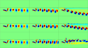
We begin by illustrating the effects of a free surface on the flow structure, as depicted in figure 2. When  $Fr$ is low, i.e. 0.2, the surface deformation is negligible, and the vortex dynamics is similar to that observed in the presence of a solid boundary (Li & Lu Reference Li and Lu2012), wherein the negative and positive vortices tend to approach each other and create dipoles that deflect away from the boundary. The surface wave does not synchronise with the motion of the flapping plate, i.e. the gap distance between the free surface and the plate varies non-uniformly. As
  $Fr$ increases to 0.6, the surface deformation becomes significant, and the gap distance between the surface and the plate remains relatively constant along the gap, giving rise to a streamlined surface wave. Simultaneously, the wake moves straight downstream, with no further deflection. As
  $Fr$ increases to 0.8, the surface deformation becomes more pronounced, and the wake behind the flapping plate loses its coherence. At some instances, localised surface sharpening and breaking can be observed. Note that the large deformation (curvature) of the free surface, not just the flapping of the plate, generates vorticities. Furthermore, at low
  $Fr$, surface waves propagate both upstream and downstream, whereas at high
  $Fr$, surface waves move downstream only. This phenomenon is explained in the following section, in conjunction with figure 4(b). Another noteworthy finding is that when
  $St=0.3$, the flow structure is affected less by the surface deformation. However, for
  $St=0.45$ and
  $St=0.6$, the impact of surface deformation on the flow structure becomes more evident.

Figure 2. Instantaneous free surface and vortex structure snapshots with  $\bar {H} = 0.5$: (a–c)
  $Fr = 0.2$, (d–f)
  $Fr = 0.4$, (g–i)
  $Fr = 0.6$ and (j–l)
  $Fr = 0.8$; (a,d,g,j)
  $St = 0.3$, (b,e,h,k)
  $St = 0.45$ and (c,f,i,l)
  $St = 0.6$. All the contour plots are at the same time instant
  $t=0.0T$, where
  $T$ is the cycle time.
In the following analysis, we systematically examine how the free surface impacts propulsion performance. Three crucial performance metrics have been established, namely the time-averaged thrust force coefficient  $C_T$, the time-averaged input power coefficient
  $C_P$ and the efficiency
  $\eta =C_T/C_P$. Coefficients
  $C_T$ and
  $C_P$ are defined as
 \begin{equation} C_T=\frac{2\left \langle\displaystyle\oint\nolimits_{S}f_x\,{\rm d}s \right \rangle}{\rho_{2} {U^{2}_{\infty}} \mathcal{C}}, \quad C_P=\frac{2\left \langle\displaystyle\oint\nolimits_{S}\boldsymbol{f} \boldsymbol{\cdot}{\boldsymbol{u}}\,{\rm d}s \right\rangle}{\rho_{2} {U^{3}_{\infty}} \mathcal{C}}, \end{equation}
respectively, where  $f_x$ represents the horizontal component of the fluid–structure interaction force
  $\boldsymbol {f}$. Two intriguing phenomena can be observed in figure 3. First, at
  $St=0.3$, there is no net thrust, and swimming closer to the surface results in a transition from drag to thrust for all
  $Fr$. However, as the surface deformation increases (higher
  $Fr$), this transition can occur only by swimming very close to the boundary. Thus, we conclude that the deformation of the free surface alone does not facilitate the drag-to-thrust transition. Second, in contrast, at a higher
  $St=0.45$ and
  $St=0.6$, there is a net thrust. When
  $Fr=0.2$, the free-surface deformation is minimal, and if the plate moves closer to the boundary, the thrust initially increases, accompanied by an increase in the input power (Dai, He & Zhang Reference Dai, He and Zhang2016). This leads to a relatively constant or slightly decreasing efficiency, similar to the effects observed with a solid boundary (Quinn et al. Reference Quinn, Moored, Dewey and Smits2014b). Interestingly, with the same flapping motion, as
  $Fr$ increases, the required input power and induced thrust both decrease, resulting in higher efficiency than in cases where the plate is far away or
  $Fr$ is small. Furthermore, the propulsive efficiency is notably maximised at an optimal Froude number of
  $Fr = 0.6$.

Figure 3. (a) Power input coefficient  $C_{P}$, (b) thrust coefficient
  $C_{T}$ and (c) efficiency
  $\eta$ as a function of the dimensionless submergence depth
  $\bar {H}$. The simulations reveal three distinct regimes: a significant-ground-effect regime (pink) for
  $\bar {H}<1$, a minor-ground-effect regime (blue) for
  $1<\bar {H}<3$ and a no-ground-effect regime (yellow) for
  $\bar {H}>3$. There is an optimal propulsive efficiency when the Froude number
  $Fr = 0.6$ and when there is net thrust in the system.
To explain the performance enhancement and the existence of an optimal  $Fr$, we first examine the flow structure illustrated in figure 2. As stated above, when the free surface undergoes deformation, a streamlined flow is induced around the flapping plate. However, we do not anticipate resonance between the free surface and the flapping plate due to the streamlined shape. Such resonance could cause more energy to accumulate in the surface waves, necessitating more input power. To support this claim, we present figure 4, which displays the frequency and propagation direction of the dominant surface waves associated with free-surface deformation. We define the dimensionless frequency as
  $\overline {f_S}={f_S}/{f}$ and the dimensionless propagation velocity as
  $\overline {V_S}={V_S}/{U_{\infty }}$. The frequency
  $f_S$ and the propagation velocity
  $V_S$ are obtained by analysing the spatial and temporal data of the surface elevation based on the Fourier transform.

Figure 4. Frequency and propagation velocity of the induced surface waves. (a) The dimensionless frequency  $\overline {f_S}$. When
  $St$ is 0.3, all cases exhibit close to the plate motion frequency. When
  $St$ is 0.45 and 0.6, at the optimal
  $Fr$, the system lies away from resonance. (b) The dimensionless propagation velocity
  $\overline {V_S}$. When
  $Fr$ is 0.2, the free-surface wave can propagate both upstream and downstream. When
  $Fr$ is 0.4, the wave can propagate slightly upstream and mostly downstream. When
  $Fr$ is 0.6 and 0.8, the wave can travel only downstream. The line colours and patterns are the same as those in figure 3.
Figure 4 illustrates a comparison of the frequency between the flapping plate and the induced surface wave, as well as the propagation velocity of the surface wave. At the small  $Fr$ value (
 $Fr=0.2$), the frequency of the free surface matches that of the flapping plate, resulting in resonance between them. As a result, the surface waves absorb a significant amount of energy from the fluid. However, as
  $Fr$ increases, the system moves away from resonance, and at the optimal
  $Fr=0.6$, the frequency ratio between the surface and plate ranges from 0.5 to 0.8; therefore, no resonance occurs at all. The presence or absence of resonance can also impact the propagation velocity of the surface waves, as presented in figure 4(b). At
  $Fr=0.2$, the wave speed is much faster than the incoming flow, and the wave propagates both upstream and downstream. However, at higher
  $Fr$ values, the wave speed becomes much smaller, requiring less energy to transport. Furthermore, because the wave speed is slower than the incoming flow, the surface waves can propagate only downstream, i.e. not upstream.
Another important factor to consider is the impact of added mass in different scenarios. The added mass stems from the kinetic energy added to a fluid by an object moving in an unsteady manner. In reality, the object's influence extends throughout the entire fluid, not limited to a specific region around the boundary. However, despite this broader influence, the concept of added mass remains invaluable in elucidating fundamental flow physics for objects moving in viscous flow (Fernando, Weymouth & Rival Reference Fernando, Weymouth and Rival2020; Reijtenbagh, Tummers & Westerweel Reference Reijtenbagh, Tummers and Westerweel2023). Figure 5 provides an illustration of the added mass in three distinct cases: a sphere positioned far from a boundary, a sphere positioned near a solid boundary and a sphere positioned close to a free surface (Brennen Reference Brennen1982). Here we only show the sphere cases because for sphere cases there exist exact solutions, even for spheres close to a solid boundary (Brennen Reference Brennen1982). When swimming in close proximity to a solid boundary (or at low  $Fr$), the added mass tends to increase as the fluid between the boundary and the body accelerates. Consequently, to maintain the same movement, both the input power and the thrust need to increase. This concept of increased added mass from Brennen (Reference Brennen1982) has been used to elucidate the scaling of lift or drag for a flapping foil near a solid boundary (Mivehchi et al. Reference Mivehchi, Zhong, Kurt, Quinn and Moored2021; Han et al. Reference Han, Zhong, Mivehchi, Quinn and Moored2024). In contrast, with a free surface, the streamlined shape of the surface allows it to follow the shape of the body, leading to less fluid acceleration between the free surface and the body. As a result, the added mass for the free surface case can be smaller than for the case where the sphere is far from the boundary. A decrease in the added mass leads to a reduction in the required power input and an increase in efficiency. Now we could also explain why there is an optimal
  $Fr$ and why the
  $Fr$ effect is not monotonic. When
  $Fr$ is very small, the free surface has negligible impact, resembling a solid boundary. On the other hand, at high
  $Fr$, significant surface deformation may occur, potentially leading to the breakup of the surface waves, which is also undesirable in performance. The added mass effect is shown in figure 6, which illustrates the horizontal and vertical velocities around the plate and in the wake region. We observe a decrease in the kinetic energy associated with the perturbed fluid within the computational domain as the Froude number increases (both horizontal and vertical velocities decrease with increasing
  $Fr$). Excessive
  $Fr$ values may lead to surface breakup, resulting in enhanced energy consumption, highlighting the existence of an optimal
  $Fr$.
$Fr$.

Figure 5. Schematic diagram of the added mass  $M_a$ under various conditions. Here, we show an example of a sphere for which there exist exact relations (Brennen Reference Brennen1982);
  $r$ is the radius of the sphere,
  $s$ is the distance from the centre of the sphere to the boundary,
  $\rho _{fluid}$ is the liquid density and
  $K$ is the added mass coefficient. When the sphere is close to the free surface,
  $K$ can be reduced to 0.5.

Figure 6. Instantaneous free surface and velocity component snapshots with  $\bar {H} = 0.5$ and
  $St = 0.45$: (a,b)
  $Fr = 0.2$, (c,d)
  $Fr = 0.4$, (e,f)
  $Fr = 0.6$ and (g,h)
  $Fr = 0.8$; (a,c,e,g) velocity component
  $U$ and (b,d,f,h) velocity component
  $V$.
$V$.
Another effect worth noticing is that when  $\bar {H}$ decreases from 3 to 1 (see figure 3), the initial decrease in thrust occurs because, at a greater distance from the free surface, the free surface effectively behaves like a solid boundary. As a result, the added mass increases, leading to a reduction in thrust. The reduction in added mass occurs only when the plate is sufficiently close to the free surface, causing deformation and minimising the added mass. This phenomenon is again consistent with the findings by Brennen (Reference Brennen1982), where he demonstrated that even a sphere approaching the free surface experiences an initial increase followed by a subsequent decrease in added mass.
4. Local dynamics
To better illustrate how the local free-surface deformation varies in relation to the kinematics of the flapping plate, figure 7 shows the instantaneous shape of the free surface at two distinct time instants: one when the plate is moving upward (figure 7 top panels) and one when the plate is moving downward (figure 7 bottom panels). When the plate is moving upward, the surface deformation is minimal for the  $Fr=0.2$ case. In contrast, for
  $Fr=0.6$ and
  $Fr=0.8$, the surface deformation closely follows the kinematics of the flapping plate. Notably, for
  $Fr=0.8$, the surface shape changes drastically behind the plate, forming a cliff-like structure, especially for larger
  $St$. A similar pattern is observed when the plate is moving downward.

Figure 7. Instantaneous free-surface deformation near the flapping plate for various  $Fr$ values, all with a consistent depth of
  $\bar {H} = 0.5$. The solid black lines represent the position of the flapping plate, while the coloured lines depict the instantaneous positions of the water–air interfaces at different
  $Fr$.
$Fr$.
The effect of local surface deformation dynamics is also reflected in the thrust and input power throughout one cycle. In figure 8, we present the instantaneous thrust force and input power over one cycle for different cases. Higher  $St$ leads to higher instantaneous thrust and input power. Notably, in the first half-cycle, where the plate moves downward from its initial position and then upward, and in the second half-cycle, where the plate first moves upward and then downward, the
  $Fr=0.2$ case shows almost the same thrust but significantly different input power. In contrast, for other
  $Fr$ values, the thrust varies considerably between the two half-cycles, while the input power remains quite similar. This suggests that when surface deformation is minimal, the instantaneous input power can increase significantly as the plate moves closer to the surface due to the acceleration of fluids between the plate and the non-deformable surface, as previously noted. For higher
  $Fr$ values, however, the surface deformation is closely linked to the kinematics of the flapping plate, resulting in much smaller differences in input power between the two cycles, especially for
  $Fr=0.6$ and
  $Fr=0.8$. On the other hand, thrust generation is not significantly associated with streamlined surface deformation.

Figure 8. Instantaneous thrust force  $C_T$ and input power
  $C_P$ for various
  $Fr$ values, all at a constant depth of
  $\bar {H} = 0.5$. In the first half-cycle, the plate moves downward from its initial position and then upward. In the second half-cycle, the plate moves upward and then downward.
5. Reynolds number dependence
This section is dedicated to enhancing our comprehension of the  $Re$ dependence. Here we focus on cases with
  $Re=400$ and
  $Re=600$, and we maintain fixed values of
  $Fr=0.6$ and
  $St=0.45$ while varying
  $\bar {H}$.
Snapshots capturing the instantaneous free surface and vortex structures at  $Re=400$ and
  $Re=600$ are illustrated in figure 9. A comparative analysis unveils both similarities and distinctions when compared with
  $Re=200$. The overall flow structure remains akin to that of the
  $Re=200$ scenario, where the wake is deflected downward when the plate is away from the surface (
 $\bar {H}> 1$), resembling cases with a solid boundary (Quinn et al. Reference Quinn, Moored, Dewey and Smits2014b). As the plate approaches the surface, the wake deflection diminishes. However, a notable difference at higher
  $Re$ is the emergence of high-curvature regions around the surface and the generation of small vortices near these areas, leading to an increased likelihood of surface breakups.

Figure 9. Instantaneous free surface and vortex structure snapshots for  $Re = 400$ and
  $Re=600$: (a,c)
  $Re = 400$ and (b,d)
  $Re = 600$; (a,b)
  $\bar {H} = 0.6$ and (c,d)
  $\bar {H} = 1.0$. For all cases,
  $Fr = 0.6$ and
  $St = 0.45$.
Figure 10 depicts the power input coefficient  $C_{P}$, thrust coefficient
  $C_{T}$ and efficiency
  $\eta$ in relation to the dimensionless submergence depth
  $\bar {H}$ for
  $Re=400$ and
  $Re=600$. The outcomes again closely resemble those for
  $Re=200$. Specifically, there is a trend of decreasing input power and increasing thrust as the flapping plate approaches the free surface, resulting in an overall enhancement in efficiency. The uniformity observed across various
  $Re$ values suggests that the mechanism influencing the enhanced propulsive performance of the flapping plate in the previous sections remains valid within the explored
  $Re$ range. Further investigation into even higher
  $Re$ regimes is warranted to comprehensively understand the
  $Re$ dependence, especially in the context of real-world applications where
  $Re$ tends to be significantly higher.

Figure 10. (a) Power input coefficient  $C_{P}$, (b) thrust coefficient
  $C_{T}$ and (c) efficiency
  $\eta$ as a function of the dimensionless submergence depth
  $\bar {H}$ with
  $Re=400$ and
  $Re=600$. Here
  $Fr$ is fixed at 0.6 and
  $St$ is fixed at 0.45. The overarching pattern observed for
  $Re=200$ remains comparable to the outcomes obtained for
  $Re=400$ and
  $Re=600$.
6. Concluding remarks
In summary, we have employed a two-fluid coupled immersed boundary method to investigate the ground effect of a flapping plate near a free surface. We observe that when  $Fr$ is small, the free-surface effect is similar to that of a solid boundary, where both the input power and thrust increase while the efficiency remains constant. However, we have discovered a new type of ground effect caused by the streamlined surface shape and decreased added mass when the surface deformation is significant, leading to decreased power input and increased efficiency. We have also analysed data from the literature on real swimmers and found that their
  $Fr$ values are consistent with the optimal
  $Fr$ value of 0.6 that we have determined in our simulations. Although our model is simple, we find that it provides a fundamental framework for understanding the ground effect originating from a free surface.
In reality, fins from aquatic animals are not always oriented vertically (most aquatic mammals), with many instances featuring horizontal orientations (most fish). We aim to delve deeper into understanding this phenomenon, exploring dependencies on Reynolds numbers to much higher ones and three-dimensional effects in future studies. Finally, we remark that in this study, the parameter space is investigated by varying one dimensionless parameter while keeping the other dimensionless parameters fixed. Because the computational costs of the simulation are high, only a limited number of parameter values are simulated. After computing power has a substantial increase in the future, more extensive combinations in the parameter space should be studied to obtain insights into the biological systems in nature.
Acknowledgements
We thank Daniel B. Quinn and Keith W. Moored for helpful discussions. L.S. was supported by the University of Minnesota. We also thank the HPC systems of Max Planck Computing and Data Facility (MPCDF) for the allocation of computational time.
Funding
We gratefully acknowledge financial support from the Max Planck Society, the German Research Foundation (DFG) from grants 521319293, 540422505 and 550262949 and the Daimler and Benz Foundation.
Declaration of interests
The authors report no conflict of interest.


 Open access