1. Introduction
The hypersonic airbreathing flight achieved by scramjet engines has gained worldwide interest (Urzay Reference Urzay2018), and many representative advances (Feng et al. Reference Feng, Huang, Zhu, Wang, Sun, Wang and Cai2021, Reference Feng2022; Tian et al. Reference Tian, Zhu, Sun, Wang, Huang, Feng, Yan, Sun and Cai2022) in recent years have brought it further towards application realization. However, it is still a complex and pressing challenge to develop a scramjet engine capable of hypersonic airbreathing flight over a wide speed range and broad altitude range. One promising approach is the use of an axisymmetric cavity configuration with transverse fuel injection in the scramjet combustor (Bulman & Siebenhaar Reference Bulman and Siebenhaar2006; Boyce et al. Reference Boyce, Tirtey, Brown, Creagh and Ogawa2011).
The axisymmetric scramjet is simple in configuration but has many advantages. It is structurally more compact and has a small wetted area, resulting in lower internal drag and thermal protection requirements. In addition, its absence of corner boundary-layer effects is also a major advantage. However, although the optical observation experiments of rectangular model scramjets can now achieve high spatio-temporal resolution (Liu et al. Reference Liu, Baccarella, Hammack, Lee, Carter and Do2017a,Reference Liu, Baccarella, Lee, Hammack, Carter and Dob; Baccarella et al. Reference Baccarella, Lee, Liu, Elliott, Freund and Lee2020), it is still not easy to obtain the transient flame structures inside axisymmetric scramjet engines. This is mainly due to the inherent limitations of complex curved profiles design/manufacturing and testing facility operating conditions, which result in precious few reports of optical observations of axisymmetric scramjets. Recently, pioneering calculation and experimental work on axisymmetric scramjets has been achieved by teams at the University of Queensland (Vanyai et al. Reference Vanyai, Grieve, Street, Denman, Mcintyre, Veeraragavan, Wheatley and Smart2019, Reference Vanyai, Landsberg, Mcintyre and Veeraragavan2021; Landsberg et al. Reference Landsberg, Vanyai, Mcintyre and Veeraragavan2021) and the University of Illinois (Liu et al. Reference Liu, Baccarella, Landsberg, Veeraragavan and Lee2019a,Reference Liu, Baccarella, Mcgann and Leeb; Baccarella et al. Reference Baccarella, Liu, Mcgann, Lee and Lee2021). Liu et al. (Reference Liu, Baccarella, Landsberg, Veeraragavan and Lee2019a,Reference Liu, Baccarella, Mcgann and Leeb) and Baccarella et al. (Reference Baccarella, Liu, Mcgann, Lee and Lee2021) first experimentally investigated the flow and combustion structure inside an axisymmetric supersonic combustor with a total temperature of 2200 K and a total pressure of 165 kPa. These conditions correspond to a flight Mach number of 7~8 and a unit Reynolds number of approximately 3 × 10⁵. The laminar-like corrugated flames observed by the hydroxyl (OH) planar laser-induced fluorescence (PLIF) technique present the supersonic combustion snapshot under low chamber pressure and low Reynolds number. Equally importantly, the studies by Landsberg et al. (Reference Landsberg, Vanyai, Mcintyre and Veeraragavan2021), Vanyai et al. (Reference Vanyai, Landsberg, Mcintyre and Veeraragavan2021) focused on comparable flight conditions and first captured hydroxyl planar laser-induced fluorescence (OH-PLIF) images at the exit of the axisymmetric supersonic combustor.
However, higher-Reynolds-number conditions are also quite common for the combustion organization environment within a scramjet combustor, e.g. when the vehicle operates at flight Mach number 4~6 (Segal Reference Segal2009; Urzay Reference Urzay2018; Liu, Baccarella & Lee Reference Liu, Baccarella and Lee2020). In these circumstances, the flow structures and combustion regimes are of equal concern. A high Reynolds number enhances turbulence, thereby facilitating the fuel–air mixing, and thus improving combustion efficiency and heat release rates. Meanwhile, the flame is affected by the flow field disturbance and undergoes more obvious morphological changes, which may be manifested as folding and stretching of the flame, or even flame quenching (Poinsot & Veynante Reference Poinsot and Veynante2005). Therefore, further in-depth studies on the flow structures and flame morphology in high-Reynolds-number conditions can help to deepen the understanding of the supersonic combustion flow field under a wide range of flight conditions.
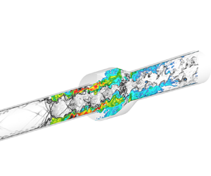
In this study, the flow and flame structures, as well as the combustion characteristics in an axisymmetric cavity-based scramjet combustor with an optically accessible test section under Mach 6 flight conditions, are investigated experimentally and numerically. With a total temperature of 1800 K and a total pressure of 1.36 MPa, the instantaneous flame structures are visualized by OH-PLIF, broadband flame emission and CH* chemiluminescence, and the wall pressure profiles are recorded by the pressure taps along the flow path. The chamber pressure ranges from approximately 0.8 to 3.5 atmospheres, and the inflow unit Reynolds number is approximately 1 × 10⁷, which are quite different from the axisymmetric model scramjet experiment reported by Liu et al. (Reference Liu, Baccarella, Landsberg, Veeraragavan and Lee2019a). To have a clearer quantitative understanding of the combustion flow field, efficient and accurate numerical methods based on the hybrid Reynolds-averaged Navier–Stokes/large-eddy simulation (HRL) framework are used here. In particular, the combustion model adopted is the recently proposed pressure-related flamelet/progress variable (FPV) model. It overcomes the shortcoming that the pressure is treated as a constant in the flamelet-like models, and it is shown to be able to accurately describe the supersonic combustion flow field where the pressure is far from homogeneous, as presented in our previous simulation study (Tang et al. Reference Tang, Wang, Huang, Sun and Wang2022a, Reference Tang, Wang, Yu, Huang, Sun, Wang, Zhao, Yang and Xiong2023b, Reference Tang, Wang, Yu, Huang, Sun, Wang, Zhao, Yang and Xiong2024). To sum up, the objective of this study is to reveal, by numerical and experimental means, the flow and flame structures, as well as the combustion regimes in the axisymmetric cavity-based combustor characterized by high Reynolds number.
2. Experimental configuration and optical measurement
2.1. Experimental configuration
The experiment was carried out on a direct-connected test rig at the National University of Defense Technology, as shown in figure 1(a), and the conditions for the 0.18-equivalent-ratio case are attached in the table next to it. The experiment simulates the Mach 6 flight conditions, corresponding to an inflow with a total temperature of 1800 K, a total pressure of 1.36 MPa and a mass flow rate of 400 g s−1. The high-enthalpy inflow is supplied by the air heater, which uses a reasonable ratio of alcohol and pure oxygen to burn and heat the air. The mass flow rate of alcohol is 28.2 g s−1, the mass flow rate of oxygen is 84.7 g s−1 and the mass flow rate of air is 287.1 g s−1. Then the airflow is accelerated by the Mach 2.5 Laval nozzle and enters the isolator. The ethylene fuel was injected from 46 mm upstream of the cavity into the supersonic flow field at an angle of 45°, and the 16 orifices were evenly distributed in the circumferential direction with a diameter of 0.75 mm. The Reynolds number at the isolator entrance is approximately 1 × 10⁷ under the current operating conditions. More details about this test rig can be found in Li et al. (Reference Li2023) and Yan et al. (Reference Yan, Sun, Tang, Li, Wang, Yang, Li, Tian, Chen and Zhu2024).
As shown in figure 1, the model scramjet engine was designed in an axisymmetric configuration, with a straight isolator of 35 mm inner diameter. The combustor features an axisymmetric cavity, with a depth of 11 mm and a length of 62 mm. The inclination angle of the cavity aft wall is 22.5°, and the downstream diverging section spans a full length of 360 mm, with an expansion angle of 2°. Two materials of the combustor and diverging section were used in the experiments. The metal test section with pressure taps was used for pressure measurement, while the combustor and diverging section made of quartz glass were used for optical observation.
The ethylene fuel was ignited by the pilot hydrogen flame. The pilot hydrogen flame was first established, and then ethylene fuel was injected and ignited. After that, the pilot hydrogen would be switched off and the ethylene flame would continue to burn independently for 600 ms. To this end, a pilot hydrogen injection module, a spark plug and an ethylene injection module were designed in sequence upstream of the cavity. The pilot hydrogen was injected at 83 mm upstream of the ethylene injection module through eight evenly spaced 1 mm diameter orifices.
The experiment designed three cases with equivalence ratios (ERs) of 0.06, 0.12 and 0.18, corresponding to ethylene mass flow rates of approximately 1.7 g s−1, 3.3 g s−1 and 4.9 g s−1, respectively. The mass flow rate was measured by a turbine flowmeter with an uncertainty of ±1.5 %.
2.2. Optical measurement
The broadband flame emission, CH* chemiluminescence and OH-PLIF imaging technique, and wall pressure measurement were used in the experiments. Wall pressure was measured by a pressure transducer connected to 16 pressure taps, broadband flame emission and CH* chemiluminescence were captured by a high-speed camera and OH-PLIF signals were captured by an ICCD camera with a bandpass filter.
The schematic diagram of the optical diagnostic system for OH-PLIF observation is shown in figure 2. A solid-state Nd:YAG laser (Spectral Physics) emitting ~532 nm radiation with a pulse energy of 350 mJ and a pulse frequency of 10 Hz was used to pump up a dye laser (PrecisionScan, Sirah Lasertechnik). The dye laser system produced a dye laser which was then frequency doubled at 283.55 nm with a pulse energy of approximately 3.5 mJ. The dye laser was tuned to excite the Q1(8) transition of OH X2Π-A2Σ+(0,1). The laser beam passed through three cylindrical lenses: a −15 mm cylindrical lens, a +290 mm cylindrical lens and a +500 mm cylindrical lens. Finally, the beam was expanded into a sheet with a width of approximately 100 mm and a thickness of 500 μm. The laser sheet entered the axisymmetric cavity combustor from top to bottom, and an ICOMS camera (Lambert GEV_B2020M) was used to capture OH-PLIF images from the side. A lens (100 mm F/2.8 CERCO, from Sodern) and a bandpass filter (Edmund 310/20) were installed in front of the ICCD camera to better collect the PLIF signals. A delay generator (DG645) was used to ensure that the ICCD camera could accurately capture the fluorescence signals.
A high-speed camera (Photon FASTCAM SA-Z) with a lens (AF Nikkor 24 mm f/2.8D) was employed to capture broadband flame emission and CH* chemiluminescence. A bandpass filter (Edmund 430/20) was used to capture the CH* chemiluminescence. The calibration, filtering and statistical processing of the images are similar to the studies of Vanyai et al. (Reference Vanyai, Grieve, Street, Denman, Mcintyre, Veeraragavan, Wheatley and Smart2019, Reference Vanyai, Landsberg, Mcintyre and Veeraragavan2021) and Wan et al. (Reference Wan, Zhu, Sun, Zheng, Zhou, Huang, Wang, Liu, Wu and Wang2023).
In addition, 16 pressure taps along the flow path were connected by tubing to the pressure scanner (PSI NetScanner 9116) to measure wall pressure. The measurement uncertainty is ±0.05 % full scale with a sampling frequency of 200 Hz.
3. Experimental results and discussion
Figure 3 shows the averaged images of broadband flame emission and CH* chemiluminescence for the three ERs, and the flame edges are outlined with white lines. Here, the flame edges are outlined by luminance thresholding. The images are normalized relative to the maximum intensity of brightness to make them comparable. The broadband flame emission is recorded by the high-speed camera at 20 000 fps, and the CH* chemiluminescence is recorded at 2000 fps. All images within the ~0.6 s effective operating time of the scramjet combustor are used for averaging. The broadband flame emission brightness is usually considered to correlate with the heat release rate in the combustion and can therefore be used to visualize the flame or heat release distribution (An, Wang & Sun Reference An, Wang and Sun2021; Landsberg et al. Reference Landsberg, Vanyai, Mcintyre and Veeraragavan2021; Rising et al. Reference Rising, Morales, Geikie and Ahmed2021; Tian et al. Reference Tian, Shi, Zhong and Le2021). Whereas the CH group is a hallmark of the extensive occurrence of combustion chain reactions, and CH* chemiluminescence can be used to identify the relative amount of heat released during the combustion process of hydrocarbon fuels (Allison et al. Reference Allison, Frederickson, Kirik, Rockwell, Lempert and Sutton2017; Baumgardner & Harvey Reference Baumgardner and Harvey2020; Cao et al. Reference Cao, Brod, Yokev and Michaels2021; Wang et al. Reference Wang, He, Tang, Li, Tian, Wan, Zhu and Sun2023).
In the broadband flame emission results, the white dashed line is the outline of the unobstructed effective observation area, the blue box line is the outline of the actual inner flow channel and the white solid line is the outline of the image edge. It can be found that the combustion heat release zones are mainly distributed in the cavity and its upstream position, and the difference in luminescence intensity reflects the difference in combustion heat release intensity at different ERs. In addition, the cavity is also heated and luminescent in the case of ER = 0.18. The CH* chemiluminescence results further show that the heat release zone is primarily concentrated in the upstream of the cavity. As the ER decreases, the heat release intensity decreases, and the location of the heat release zone gradually moves slightly downstream. Overall, the stabilized combustion can be observed in the jet wake at all three ERs, thanks to the recirculation zones formed by the transverse jets on the one hand, and the high total temperature environment that drives auto-ignition as an assistant mechanism on the other hand.
Figure 4 shows the instantaneous and averaged OH-PLIF images, with the yellow dashed line representing the contour of the combustor flow channel. Although OH is an intermediate product, it generally appears in the reaction mixing layer adjacent to the thermal product zone. Therefore, the OH-PLIF technique is often used to characterize the product zone, and it has been successfully used in many representative experiments to capture fine instantaneous flame structures in supersonic combustion flow fields (Micka & Driscoll Reference Micka and Driscoll2012; Gamba & Mungal Reference Gamba and Mungal2015; Fulton et al. Reference Fulton, Edwards, Cutler, Mcdaniel and Goyne2016).
It can be visualized that thick, hot flames are observed in the jet wake for the 0.12 and 0.18 ERs, with the flame tongues highly creased and intruding into the main flow, suggesting that there is intense combustion heat release in the upstream jet wake. High-temperature flames are also evident in the interior of the axisymmetric cavity. At the ER of 0.06, it is observed that the high-temperature product zone is mainly in the cavity, and the wrinkles on the edge of the flame are relatively small. In the upstream of the cavity, its OH-PLIF signals are relatively weak. However, combined with the results of CH* chemiluminescence, it can be inferred that there is also a certain intensity of combustion in the upstream jet wake. It is speculated that some signals near the wall may be masked due to scattering or distortion of the thick glass tube.
The pressure measurement results along the flow path are shown in figure 5. As the ER increases, the pressure rise caused by combustion gradually increases, which reflects the difference in heat release intensity. Among them, at the ERs of 0.12 and 0.18, there is a significant pressure rise upstream of the fuel injection, and the peak pressure appears near the rear wall of the cavity. Compared with the cold flow field, the chamber pressure is significantly increased in the combustion flow field. In contrast, at the ER of 0.06, the pressure upstream of the cavity does not increase significantly, and the pressure rise in the combustor is also relatively smaller. Overall, the pressure peaks at the cavity and gradually decreases in the downstream expansion section. This trend is mainly related to the change in cross-sectional area of the flow path as well as heat addition. The constriction of the flow path by the cavity rear wall leads to a deceleration of the flow and an increase in pressure, while heat addition from combustion or viscous heating also leads to an increase in static pressure.
To sum up, the jet-wake flame stabilization mode is the main mechanism for maintaining combustion stability under the current high total temperature conditions. The high heat release zone is mainly concentrated in the jet wake upstream of the cavity, where the flame presents as thick and hot, and the flame tongue is folded and twisted, apparently intruding into the mainstream, indicating a fast combustion heat release process.
4. Computational methodology and validation
To reveal the typical flow field characteristics and combustion regimes under the current high-Reynolds-number conditions, further numerical studies were mainly carried out for the ER = 0.18 case.
4.1. Numerical method
The numerical calculations were performed using an in-house three-dimensional unsteady compressible flow solver coupled with a pressure-related FPV model, and the program was implemented through a hybrid parallel algorithm of MPI and CUDA. The code was examined in our previous study (Tang et al. Reference Tang, Wang, Huang, Sun and Wang2022a,Reference Tang, Wang, Li, Huang, Sun, Wang, Zhao and Yub, Reference Tang, Wang, Yu, Huang, Sun, Wang, Zhao, Yang and Xiong2023b, Reference Tang, Wang, Yu, Huang, Sun, Wang, Zhao, Yang and Xiong2024). To reduce the computational cost, the HRL approach was employed, which is based on the work of Baurle (Reference Baurle2017). The turbulence model in the RANS part is a classical turbulent kinetic energy k and specific dissipation rate $\omega$ Shear-Stress Transport (SST) turbulence model (Menter Reference Menter1994), and the one-equation sub-grid-scale model proposed by Yoshizawa & Horiuti (Reference Yoshizawa and Horiuti1985) is used in the large eddy simulation (LES) part. The governing equations include the spatially filtered mass, momentum and total energy equations as well as the transport equations for the mixture fraction $\tilde{Z}$, the unnormalized progress variables ${\tilde{Y}_C}$ and the mixture fraction variance $\widetilde {{{Z^{\prime\prime}}^2}}$, and the ideal gas equation is also adopted. More details can be found in Tang et al. (Reference Tang, Wang, Yu, Huang, Sun, Wang, Zhao, Yang and Xiong2024).
The flamelet-like models are a class of efficient and intuitive combustion models (Pitsch Reference Pitsch2006). Since their promotion to supersonic combustion by Oevermann (Reference Oevermann2000), they have been continuously developed for the numerical simulation of compressible reactive flows (Saghafian et al. Reference Saghafian, Terrapon and Pitsch2015b; Ladeinde & Lou Reference Ladeinde and Lou2017; Drozda, Quinlan & Drummond Reference Drozda, Quinlan and Drummond2020; Tang et al. Reference Tang, Wang, Huang, Sun, Wang, Zhao and Yu2023a), and among which the FPV model is widely used for its ability to completely map the flamelet solution space (Pierce & Moin Reference Pierce and Moin2004; Ihme & Pitsch Reference Ihme and Pitsch2008a,Reference Ihme and Pitschb). The FPV model relies on a pre-tabulated flamelet database. This requires first solving the flamelet equations to obtain a laminar flamelet database, and then using the beta and delta probability density functions (PDFs) for the mixture fraction and the progress variable, respectively. In this way, during the reactive flow simulations, the scalars $\tilde{Z}$, $\widetilde {{{Z^{\prime\prime}}^2}}$and $\tilde{C}$ are solved and used to query the flamelet database, and the thermo-chemical state, including the species mass fractions and heat release rate, can be interpolated. Therefore, the FPV model can allow for efficient computation.
However, since the pressure pulsations in the supersonic combustion flow field are significant, the standard FPV model using a flamelet database tabulated at constant pressure is insufficient to accurately describe the complex combustion system (Gao, Jiang & Lee Reference Gao, Jiang and Lee2017). Pressure is a key influencing factor on the combustion heat release rate, and therefore its effect should be emphasized in combustion modelling, as some previous studies have pointed out (Saghafian et al. Reference Saghafian, Shunn, Philips and Ham2015a; Ladeinde, Lou & Li Reference Ladeinde, Lou and Li2019). To take into account pressure effects without significantly increasing computational cost, the recently proposed pressure-related FPV model (Tang et al. Reference Tang, Wang, Huang, Sun and Wang2022a) is adopted, with the flamelet equations solved by FlameMaster (Pitsch Reference Pitsch1998). In this model, apart from the key model parameters $\tilde{Z}$, $\widetilde {{{Z^{\prime\prime}}^2}}$and $\tilde{C}$, the local pressure is additionally introduced to scale and interpolate the flamelet database. The tabulation temperature for the oxidant side and the fuel side are 1000 K and 300 K, respectively. To obtain the pressure scaling coefficient table, the tabulation pressures are set to 0.5, 1.0, 1.5, 2.0, 2.5 and 3.0 bar at first according to the experimental pressure range, and then the pressure scaling coefficient table can be calculated and stored. In the flow computing phase, the mass fraction of all species, progress variable source term and heat release rate can be directly obtained from the benchmark flamelet database, and the pressure scaling is implemented to account for pressure effects. Details of its implementation and validation can be found in our previous studies (Tang et al. Reference Tang, Wang, Huang, Sun and Wang2022a, Reference Tang, Wang, Yu, Huang, Sun, Wang, Zhao, Yang and Xiong2023b, Reference Tang, Wang, Yu, Huang, Sun, Wang, Zhao, Yang and Xiong2024).
The study utilizes the UCSD ethylene/air combustion mechanism (UCSD 2016) with the unity Lewis number assumption. The optimized progress variable (Tang et al. Reference Tang, Wang, Li, Huang, Sun, Wang, Zhao and Yu2022b) in this study is ${Y_\textrm{C}} = {Y_{\textrm{CO}}} + 0.37185{Y_{{\textrm{H}_\textrm{2}}\textrm{O}}}$, and the temperature is implicitly solved using the method proposed by Oevermann (Reference Oevermann2000).
The flow solver uses the finite volume method and employs the third-order explicit Runge–Kutta method for the time marching scheme. A central-upwind fourth-order weighted essentially non-oscillatory (WENO-CU4) scheme (Li et al. Reference Li, Wang, Zhao, Sun, Xiong and Tang2020) is used for spatial inviscid fluxes. The global time step is set to 8 × 10⁻¹⁰ s. The computation reaches convergence after approximately five flow-through times (5 L/U), where L is the length of the computational domain, and U is the mean inflow velocity. The time averaging is performed two flow-through times (2 L/U) after the convergence.
The computational domain and boundary conditions are shown in figure 6(a). To reduce the computational grid, the length of the diverging section is reduced to 120 mm in the simulation. The ethylene fuel is injected into the flow field from 16 injectors evenly distributed in the circumferential direction, with a 45 degree injection direction. The fuel injector is modelled as a strong contraction, consistent with the true physical design. This results in a sonic, choked, fuel jet. The study adopts a structured mesh, including four boundary conditions: supersonic inlet, outlet, adiabatic no-slip wall and fuel injection. Figures 6(b) and 6(c) show the mesh near the cavity and the injectors, respectively. Refinement is performed near the wall and the injectors, with the first layer of the mesh near the wall having a size of 0.004 mm, satisfying y+ ≈ 1. The mesh has approximately 72 million cells in total.
To examine the grid resolution, two LES turbulence criteria are employed for verification before proceeding with the subsequent simulations. The parameter M, proposed by Durbin (Reference Durbin2001), evaluates the proportion of the resolved turbulent kinetic energy (TKE) to total TKE, i.e. $M = {k_{sgs}}/{k_{res}}\textrm{ + }{k_{sgs}}$, where ${k_{sgs}}$ is the sub-grid turbulent kinetic energy, ${k_{res}}$ is the resolved TKE. Pope argues that a well-resolved LES requires at least 80 % of the TKE to be resolved, thus implying that the grid resolution should permit M ≤ 0.2. Pope's resolution criterion shown in figure 7(a) indicates that over 80 % of the TKE has been resolved, which implies that the present solver as well as the mesh can capture both the large-scale vortex structures and the relatively smaller flow features.
Figure 7(b) shows the turbulent power spectral density (PSD) of the velocity at two positions in the shear layer of the transverse fuel jet, where a segment with a slope close to −5/3 can be found in both curves. This is in good agreement with Kolmogorov's −5/3 scaling law, suggesting that the present solver and mesh are capable of capturing multiscale features in the turbulent flow fields (Kawai & Lele Reference Kawai and Lele2010; Zhao, Li & Ye Reference Zhao, Li and Ye2021).
4.2. Comparison between experimental and calculated results
Experimental and calculated results are presented and compared first before further analysis, and for a more comprehensive comparison and verification, the wall pressure profile of ER = 0.06 is additionally provided here. As shown in figure 8, the combustion heat release in this condition is quite intense. The flame is mainly distributed in the jet wake and visible PLIF signals can be captured in almost the entire cavity. The flame core is thick, and the flame tongue noticeably contracts the mainstream. Qualitatively, the instantaneous distributions of the calculated temperature are in good agreement with the hot product zones identified by the OH-PLIF signals. Quantitatively, the wall pressures calculated by using both the HRL and RANS methods are in high agreement with the experimental profile, indicating that the present calculations are capable of accurately reproducing the combustion flow field. In the following section, further analysis is presented mainly based on the ER = 0.18 case.
5. Numerical results and discussions
5.1. Basic flow field structure
The mixing process of fuel in supersonic flow fields is mainly dominated by large-scale flow structures, rather than diffusion processes at the microscopic level. The compressible flow, through the formation and evolution of large-scale vortices and a shear layer, creates multiple scales of mass and energy transport between the fuel plume and the supersonic mainstream, thereby promoting the mixing process. Figure 9 shows the distribution of streamwise vorticity at different cross-sections in the cold and combustion flow fields, where the fuel plume is outlined by the iso-surface of mixture fraction. It can be seen that, compared with the combustion flow field, the cold flow field shows larger flow vorticity in the middle and downstream parts of the cavity, indicating that the cold flow field actually has higher turbulence intensity at these positions. In the upstream of the cavity, the streamwise vorticity of the combustion flow field is significantly higher, the fuel plume becomes distorted and turbulent and the mixing rate is also accelerated.
In supersonic flow fields, intense interactions between shockwaves and turbulent flows can be observed, which significantly affect the generation and distribution of vortices. Figures 10(a) and 10(b) present the instantaneous vorticity distributions (logarithmic form) in the cold and combustion flow fields, respectively, with the flow structures depicted in the background. In the cold flow field, under the shockwaves’ induction and the shear effects of the cavity, the enriched vortex structures appear in the rear part of the cavity. In contrast, in the combustion flow field, the appearance of the shock train causes the vortex distribution to move upstream significantly, and the vorticity generated by the shear effects is reduced in the cavity and its downstream.
Two probes are placed near the shear layer and the rear wall of the cavity, as shown in figure 10(b). The pressure variations over time in the cold and combustion flow fields are recorded, and the fast Fourier transform (FFT) results are given in figures 10(c)~10(f). In the cold flow, the dominant frequency at these two positions is relatively higher than that in reactive flow, indicating a smaller scale of the dominant flow structure. The multiple peaks present at higher frequencies suggest that multiple scales of smaller eddies jointly dominate the vortex evolution process, exhibiting a strong turbulent energy cascade. In contrast, both locations in the combustion flow field show a consistent and smaller dominant frequency, suggesting the formation of large-scale, high-energy flow structures and that the flow structures at these two locations are likely to be intrinsically related. Compared with the cold flow field, the combustion-induced heat release and density drop in the hot flame result in the local positive dilatation, thereby injecting kinetic energy into the turbulent flow. This backscatter phenomenon may indeed be the reason for the formation of higher-frequency structures in the combustion flow field.
Figure 11 compares the one-dimensional distribution of TKE and Reynolds shear stress (RSS) in cold and combustion flow fields. A surge in turbulence intensity is observed in cold flow near the rear wall of the cavity, and an early rise in turbulence intensity is noticed in the combustion flow field upstream of the cavity. Compared with the cold flow field, the turbulence intensity of the combustion flow field is weakened in the cavity and the downstream diverging section. The profiles of TKE and RSS consistently reflect the above features.
To explicate the mechanism of vorticity alteration in the flow field, the compressible vorticity transport equation is introduced here (Cao et al. Reference Cao, Brod, Yokev and Michaels2023)
where the right-hand side of the equation is, in order, the Convection Term, the vorticity stretching term (VS), the volumetric expansion term (VE), the baroclinic term (BT) and the diffusion term.
In compressible flow fields, the contributions of the VS, VE and BT terms are relatively significant. Among them, the dot product of the vorticity vector with the velocity gradient tensor, also known as the VS term, triggers the transformation of the vortex structure from large scale to small scale. The VE term describes the vorticity change caused by the volume change of the fluid element, which is more significant in compressible flows. The BT represents the contribution of non-parallel pressure and density gradients to the vorticity.
The one-dimensional distributions of the alterations in vorticity, VS, VE and BT due to combustion are given in figure 12. The vorticity upstream of the cavity is found to be enhanced in the combustion flow field, whereas in the cavity and its downstream part, the vorticity in the combustion flow field shows a pronounced decrease. A strong correlation can be noticed in the changes in the VS term and the vorticity magnitude, suggesting that the VS term is the main factor triggering the alterations of the vorticity. The impact of the VS term is particularly evident in the cavity and its downstream flow field, where the hot flame intrudes considerably into the centre of the flow path. The gas within the high-temperature reactive zone expands, leading to a decrease in the velocity gradient and a decrease in the vortex stretching term.
Upstream of the cavity, the BT and VE terms are the key factors to enhance the vorticity generation, which is a manifestation of the shock-induced turbulence. In the combustion flow field, a shock train is formed in the centre of the flow path, starting upstream of the fuel injection. Induced by the leading edges of the shock train, several separation bubbles are formed with a large density gradient at the interface, which interacts with the pressure gradient due to the shockwave to generate the BT term. The energy transferred by the shock to the near-wall boundary layer or fuel plume also leads to the compression of the local fluids, which is the cause of the VE term.
Notably, combustion alters the flow field vorticity in two ways. The expanded reactive flow contracts the mainstream, causing a shock train to appear upstream of the fuel jet. In this way, combustion indirectly intensifies the upstream vorticity, and this conclusion is also supported by Cisneros-Garibay, Pantano & Freund (Reference Cisneros-Garibay, Pantano and Freund2022). Conversely, in the cavity and its downstream, the extensive high-temperature zones cause the fluid density and velocity gradient tensor to decrease, which directly leads to a decrease in the vortex stretching term.
The one-dimensional distributions of the turbulent intensity are shown in figure 13(a). Here, the turbulence intensity is evaluated through the fluctuating velocity and average velocity, i.e. I = u′/U. It can be seen that, in the cold flow field, the turbulent intensity upstream of the cavity is relatively low, while the flow velocity varies drastically near the cavity and the turbulent intensity peaks rapidly (approximately 120 %). The turbulent intensity downstream of the cavity gradually decreases to a level of approximately 30 %. In the combustion flow field, on the other hand, from the injection position to the cavity, the turbulent intensity is roughly 30 %, while downstream of the cavity the turbulent intensity gradually decreases to a level of approximately 10 %. The one-dimensional distributions of the Mach number and static pressure are shown in figure 13(b). It can be seen that, within the main heat release zone in the cavity and its upstream region, the flow is overall subsonic with localized thermal choke. The shock train formed in the centre of the flow channel resembles a thermal throat, where the pressure level is relatively high, while downstream of the cavity the fluid is continuously accelerating, and the static pressure is gradually decreasing.
Figure 14 shows the instantaneous distribution of the important products H2O, CO2, CO and OH in the combustion flow field, with the instantaneous flow structures also shown in the background. It can be found that the cavity is also an important hot product zone. The interior of the cavity is enriched with a large amount of end products H2O and CO2, indicating that the cavity has a high mass exchange efficiency with the mainstream, allowing its internal flame to be self-sustained. The intermediate product CO is mainly distributed in the upstream of the cavity, whereas it is relatively less in the interior of the cavity, indicating that most of the fuel in the upstream of the cavity has already completed the process from initial decomposition to the generation of end products. Therefore, the overall combustion process is quite fast.
5.2. Combustion mode analysis
Figure 15 provides a macroscopic description of the combustion flow field, including temperature, heat release rate (HRR), effective mixing area ratio and combustion efficiency. Here, the combustion efficiency is evaluated by the amount of product produced, i.e. ${\eta _{comb}} = \int {\rho u{Y_{prod}}\,\textrm{d}A/{{\dot{m}}_{prod\_max}}}$, where $\rho$ is the density, ${Y_{prod}}$ has the same form as the progress variable, and ${\dot{m}_{prod\_max}}$ is the product mass flow rate when the fuel is completely converted into the product.
The effective mixing area ratio is defined as
The jet wake upstream of the cavity is the main heat release region, where local temperature has increased due to heat addition. Combined with the OH-PLIF results, the combustion is identified as being in the jet-wake stabilization mode. This is also the flame stabilization mode in Liu's experiment (Liu et al. Reference Liu, Baccarella, Mcgann and Lee2019b), indicating that the present condition is still sufficient for ethylene fuel to self-ignite and achieve stable self-sustaining flames.
However, different from Liu's experiment (Liu et al. Reference Liu, Baccarella, Mcgann and Lee2019b), the cavity is also an important reactive zone in this study. Although its heat release level is not as high as that of the upstream flame, the cavity provides a favourable environment with low velocity and high temperature for reactive flow, promoting further improvement of mixing efficiency and combustion efficiency. In addition, as can be seen from the comparison of the ${\varphi _{mix}}$ profiles in figure 15(b), it increases rapidly in the combustion flow field upstream of the cavity, which is mainly driven by the higher local vorticity.
Moreover, the shock-enhanced combustion has been emphasized in recent research on high-enthalpy supersonic combustion (Capra et al. Reference Capra, Boyce, Kuhn and Hald2015; Huete et al. Reference Huete, Sánchez, Williams and Urzay2015; Vincent-Randonnier et al. Reference Vincent-Randonnier, Sabelnikov, Ristori, Zettervall and Fureby2019), and this phenomenon can also be observed in this study. In addition to inducing vorticity, another important role of shockwaves in reactive flow is to greatly accelerate the local chemical reaction rate through the surge of local pressure and temperature. Figure 16 shows the distribution of an indicator ${I_{qc}}$ for the shock-enhanced combustion. Similar to Zhao et al. (Reference Zhao, Li and Ye2021), this indicator is defined as ${I_{qc}} = \boldsymbol{\nabla }p\boldsymbol{\cdot }\boldsymbol{\nabla }{\bar{\dot{\omega }}_C} \cdot |{\bar{\dot{\omega }}_C}|/|{\bar{\dot{\omega }}_C}{|_{max}}$, where ${\bar{\dot{\omega }}_C}$ is the source term of the progress variable. The indicator ${I_{qc}}$ characterizes the enhancement effect of shockwave on the chemical reaction rate. It is found that the distribution of the indicator is highly consistent with that of high-temperature thermal products, suggesting that the shockwaves strengthen the combustion. Several near-wall separation regions are induced in the combustion flow field, where stable flames can be noticed. These separation regions are inherently high-temperature, low-velocity environments that are favourable for self-ignition of the internal entrained fuel. As the shockwave sweeps through these separation regions, the high pressure propagates inwards, and the internal ignition induction time will be greatly reduced. If there is sufficient fuel in these regions, premixed combustion will then form internally and be accelerated. The accurate capture of this phenomenon also indicates that the combustion model can account for the effect of the flow field pressure variations on the chemical reaction.
Figures 17(a) and 17(b) shows the instantaneous distributions of Mach number and FlameIndex, and correspondingly, figures 17(c) and 17(d) respectively show their bivariate kernel density estimations with the HRR (logarithmic form). The sonic lines are depicted with black solid lines in the contours. FlameIndex is calculated in the same way as Jin et al. (Reference Jin, Song, Wang, Gao, Luo and Fan2021), Tang et al. (Reference Tang, Wang, Huang, Sun and Wang2022a), with negative values representing diffusive combustion and positive values representing premixed combustion. But note that, since the gradient information in the definition of FlameIndex is not obtained directly from the grid elements themselves, this formula is a relatively crude description of the premixed/non-premixed nature. Subsonic combustion is mainly observed within the cavity and its upstream near-wall reactive zones. It occupies an area comparable to the supersonic reactive zone (which accounts for approximately 58 %), but some of these subsonic flames are observed to have higher HRR (peak value exceeding 1 × 10⁹ J (m3s)−1). However, most supersonic reactive flows have Mach numbers around 1.5 with a lower HRR of around 1 × 10⁸. An overall partially premixed combustion can be observed, in which the proportion of the diffusion flame (which accounts for approximately 54 %) and its HRR are slightly higher. The diffusion flame is found to package a large amount of twisted premixed flame. There are two main reasons for the occurrence of this partially premixed pattern: one is that the fuel jet is wrapped and burns in the oxygen-enriched airstream and reaches late stage of combustion, and the other is that the local turbulent motions distort, stretch or isolate a partially premixed flame.
The turbulent combustion regime is depicted in Figure 18 in (Ret, Da)-coordinates (Mura, Techer & Lehnasch Reference Mura, Techer and Lehnasch2022), where the turbulent Reynolds number is evaluated by $R{e_t} = {k^2}/(\langle \nu \rangle \varepsilon )$. The Damköhler number $(Da = {\tau _f}/{\tau _c})$ is the ratio of the flow characteristic time scale to the chemical reaction characteristic time scale. When Da > 1, it indicates that the chemical reaction rate is relatively faster, and it belongs to the fast-chemistry regime. Conversely, if Da < 1, it belongs to the slow-chemistry regime. In this study, the chemical reaction characteristic time is calculated in the same way as that of the PaSR (partially stirred reactor) model. The flow characteristic time scale is derived from ${\tau _f} = {L_t}/u^{\prime}$, where the characteristic velocity fluctuation is evaluated by the resolved TKE, i.e. $u^{\prime} = \sqrt {2{k_{res}}/3} $, and the turbulence integral scale is estimated by ${L_t} = {u^{\prime 3}}/\varepsilon $, with $\varepsilon $ the resolved dissipation rate (Poinsot & Veynante Reference Poinsot and Veynante2005).
The combustion processes are found to be characterized by large Damköhler numbers (Da > 10) and small Karlovitz numbers (Ka < 1), allowing the basic assumption of the flamelet model to be satisfied. The turbulent Reynolds number of the reactive flow is around 104 and Da is concentrated mainly in the range of 102 to 104.
Most combustion occurs in the corrugated or wrinkled flamelet regime, with a small portion in the thin reaction zone regime. As can be seen in figure 16, the flame front appears a folded and twisted structure, with numerous ridges, troughs or small-scale wrinkles. The flame tongues have high curvature and are surrounded by the unburned gas and burnt products. In the corrugated and wrinkled flamelet regime, the smallest vortex structure is still larger than the flamelet thickness, the vortex can only alter the shape of the flame without intruding into it, allowing for a high degree of flame stabilization. Therefore, in this case, the folded and twisted structure at the flame leading edge increases the flame surface area and improves contact between the reactants without quenching the flame, which facilitates both mixing and combustion, reflecting the contribution of turbulence.
The possible supersonic combustion regimes proposed by Ingenito & Bruno (Reference Ingenito and Bruno2010) and Balakrishnan & Williams (Reference Balakrishnan and Williams1994) are also presented in Figure 18, with red lines and green lines boxed, respectively. The study of Ingenito & Bruno (Reference Ingenito and Bruno2010) focused on low turbulence intensity conditions (0.5~10 %) at flight Mach numbers 7~9, while Balakrishnan & Williams (Reference Balakrishnan and Williams1994) considered high turbulence intensity conditions (up to 50 %) at flight Mach numbers 1~4. The scramjet combustor in this study corresponds to a Mach 6 flight condition, where the Reynolds number will typically be smaller than that in the lower flight Mach number case. Therefore, it is reasonable that the obtained combustion regime lies near the left border of the regime proposed by Williams.
In addition, the shockwave, turbulence and flame exhibit strong interactions in the current scramjet combustor. The processes and mechanisms involved are so complex that figure 19 depicts only some of the typical processes with a view to summarizing and deepening the understanding. As shown earlier in figure 16, the shockwave is an important feature of the compressible reactive flow, and the coupling of the shockwave with other flow structures makes the supersonic turbulent combustion more complicated. When acting on the fuel flow, the shockwave can induce an increase in the VE and the baroclinic torque term to augment the turbulence intensity; it can also enhance combustion by inducing local pressure and temperature rises, which can shorten the ignition induction period and promote the chemical reaction rate. As shown in figures 12 and 9, the large amount of reaction heat released by combustion can alter the overall flow structure, e.g. by forming stronger pre-combustion shock trains in the isolator; combustion also allows the interior of the flame zone to heat up and expand, leading to a reduction in the local velocity gradient and vortex stretching term, which in turn weakens the turbulence intensity. In the current working condition, as shown in figure 18, where the corrugated flamelet regime dominates, turbulence can facilitate the combustion reaction by increasing the flame surface area and enhancing the mixing of fresh air with the reactants.
To assess the effects of Reynolds numbers, we also performed an additional simulation by reducing the inflow Reynolds number to 1/10 of that of the experiment. And to ensure a consistent ER of 0.18, the inflow static pressure and the fuel injection pressure are both changed to 1/10 of their original values. The calculation grid and methodology are also consistent. The results of the low-Reynolds-number case are briefly presented in the following figures.
As can be seen in figures 20(a) and 20(b), when the Reynolds number is reduced to 1/10 of the original, the intuitive change is that the flame stabilization mode switches from the jet-wake stabilization mode to the cavity shear-layer mode, and the overall heat release intensity is reduced. The one-dimensional distributions of temperature and HRR also illustrate this change, as shown in figure 20(c). In addition, the reduction in Reynolds number results in a decrease in both mixing efficiency and combustion efficiency, as can be seen in figure 20(d).
For this low-Reynolds-number case, figure 21 gives the statistical analysis of combustion regimes based on the bivariate kernel density estimation of Re t and Da. It can be seen that, as the Reynolds number decreases, the proportion of slow-chemistry regimes in the combustion flow field increases, e.g. thin reaction zones, which have smaller Da. The slower mixing efficiency and combustion efficiency are complementary to the presence of these slow-chemistry regimes.
However, it is important to note that such a low-Reynolds-number condition corresponds to a very low inflow static pressure and a high flight altitude, which is not easily encountered at the current Mach 6 flight condition. Therefore, the low-Reynolds-number case here has not been analysed at length, but only for the purpose of intuitively illustrating the impact of the Reynolds number.
In summary, the increase in Reynolds number has led to significant changes in the overall flame structures and combustion regimes, and the experimental and simulation results together demonstrate that the reaction heat is released quickly and in large quantities in the jet wake upstream of the cavity. On the one hand, the combustor provides a high-pressure environment, resulting in an accelerated chemical reaction rate and a rapid heat release within a limited residence time. On the other hand, the higher Reynolds number leads to a higher degree of premixing and a more homogeneous mixing of the fuel and the oxidant, which improves the combustion efficiency. In addition, the formation and dissipation of vortices and turbulence are accelerated in this high-Reynolds-number condition, which leads to rapid mixing and diffusion of intermediates and promotes complete combustion of the fuel.
6. Conclusions
This study numerically and experimentally investigates flow structures and combustion regimes in an axisymmetric cavity-based scramjet combustor at Mach-6 flight conditions. In addition to the novel visualization of the instantaneous flame structure in the axisymmetric cavity-based combustor, the hybrid RANS/LES approach allows for the accurate reproduction and in-depth analysis of the combustion flow field, thus deepening the understanding of the flow structures and inherent combustion regimes within the turbulent combustion process under the high-Reynolds-number condition.
The jet-wake flame stabilization mode is observed in this study. Intense heat release is found in the jet wake upstream of the cavity, and the flame is mainly distributed in the jet wake and almost the whole cavity. The flame core is thick, and the flame tongue significantly contracts the mainstream. The axisymmetric cavity facilitates further improvements in mixing and combustion efficiency.
A multi-regime combustion process is evidenced in this study. Supersonic combustion (which accounts for approximately 58 %) and subsonic combustion jointly dominate the combustion in comparable proportions, with some subsonic combustion exhibiting higher heat release (peak value exceeding 1 × 10⁹ J (m3s)−1). Partially premixed flame is observed, with the diffusive combustion accounting for a slightly higher proportion (which accounts for approximately 54 %). A considerable quantity of twisted premixed flame is found to be packaged within the diffusion flame. Most combustion is found to occur in the corrugated or wrinkled flamelet regime (approximately 102 < Da < 104, 103 < Ret < 105).
The shockwave plays a critical role in both vorticity generation and combustion enhancement. The former is mainly manifested in the early rise in the upstream vorticity, which results from the strengthening of the volumetric expansion and BT by the combustion-induced shock train. The latter is achieved by the chemical reaction rates facilitated by the shockwaves through the pressure and temperature surge.
Combustion shows a remarkable effect on the flow structures and turbulence intensity throughout. On the one hand, combustion intensifies the interaction between the shockwave and the turbulent flow, which contributes to the formation of an intense shock train upstream and, thus, indirectly to the generation of local vorticity. On the other hand, combustion reduces the density and velocity gradient in the hot reactive region, decreasing the vortex stretching term and directly leading to a reduction in local vorticity.
Turbulence, in turn, also makes an important contribution to the combustion process. On the one hand, it enhances the effective mixing of fuel and oxidant through multiscale vortices, and on the other hand, it increases the flame surface area by forming a folded and twisted flame structure. In the current combustion regime, the fresh air can be transported to the flame leading edge without quenching it, thereby accelerating flame propagation and enhancing flame stabilization.
Nomenclature
- C
progress variable
- Da
Damköhler number
- I
turbulent intensity
- ${I_{qc}}$
indicator for the shock-enhanced combustion
- FI
Flame Index
- Ka
Karlovitz number
- ${k_{sgs}}$
sub-grid turbulent kinetic energy
- ${k_{res}}$
resolved turbulent kinetic energy
- $\dot{m}$
mass flow rate
- Ma
Mach number
- p
pressure
- $R{e_t}$
turbulent Reynolds number
- ${L_t}$
turbulence integral scale
- ${\tau _c}$
chemical reaction characteristic time scale
- ${\tau _f}$
flow characteristic time scale
- Y
species mass fraction
- ${Y_C}$
unnormalized progress variable
- $\boldsymbol{\omega }$
vorticity
- ${\bar{\dot{\omega }}_C}$
source term of the progress variable
- Z
mixture fraction
- $\widetilde {{{Z^{\prime\prime}}^2}}$
mixture fraction variance
- $\rho$
density
- $\phi$
equivalence ratio
- Superscripts
- $\,\bar{}$
Reynolds average
- $\,\,\widetilde {}$
density-weighted Favre average
Supplemental movie
Supplementary movie is available at https://doi.org/10.1017/jfm.2024.827.
An animated movie of temperature contours for the combustion flow field can be viewed online.
Funding
This work is supported by the National Natural Science Foundation of China under grant nos. 11925207, 12322211, 92252206 and T2221002.
Declaration of interests
The authors report no conflict of interest.