Hostname: page-component-7bb8b95d7b-495rp Total loading time: 0 Render date: 2024-10-04T09:18:18.448Z Has data issue: false hasContentIssue false

Droplet impact on a superhydrophobic solid substrate with a superhydrophilic annulus

Published online by Cambridge University Press:  02 October 2024

Ziqiang Ma
Affiliation:
School of Mechanical Science and Engineering, Huazhong University of Science and Technology, Wuhan 430074, PR China
Wanqiu Zhang
Affiliation:
School of Mechanical Science and Engineering, Huazhong University of Science and Technology, Wuhan 430074, PR China
Qi Zhang
Affiliation:
School of Mechanical Science and Engineering, Huazhong University of Science and Technology, Wuhan 430074, PR China
Xinping Zhou*
Affiliation:
School of Mechanical Science and Engineering, Huazhong University of Science and Technology, Wuhan 430074, PR China State Key Laboratory of Intelligent Manufacturing Equipment and Technology, Huazhong University of Science and Technology, Wuhan 430074, PR China
*
Email address for correspondence: [email protected]

Abstract

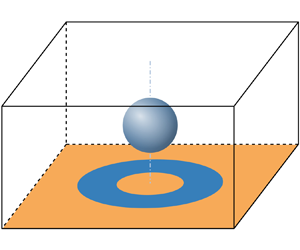
Direct numerical simulations of the droplet impact on a flat solid surface with an annular part are conducted. We investigate droplet impact on a superhydrophobic substrate with a superhydrophilic annulus to understand the formation conditions of droplets in different states. The location and size of superhydrophilic annulus are carried out through the phase diagram. We describe the formation process of droplets in three different states and the spreading radius with time to catch the rupture time of the film. Two different ruptures occur in the spreading stage or the retraction stage, respectively. The rupture times from these two mechanisms observed numerically are found to be a key factor resulting in partial rebound and lens-shaped/ring-shaped droplets. Finally, the influence of non-dimensional numbers on the formation of the ring-shaped droplet is demonstrated. The Weber number can alter the amplitude of the up and down oscillation on the droplet's upper surface, while the Froude number affects primarily the time to form the central penetrating hole. This gives the guidance and method to control the ring-shaped droplets formation time.

JFM classification

Type
JFM Papers
Copyright
© The Author(s), 2024. Published by Cambridge University Press

1. Introduction

Droplet impact on a solid surface exists extensively in nature and industry (Thoroddsen, Etoh & Takehara Reference Thoroddsen, Etoh and Takehara2008), with applications ranging from inkjet printing to self-cleaning and anti-icing. Recently, droplet impact on a solid surface has been one of the hot study areas (Josserand & Thoroddsen Reference Josserand and Thoroddsen2016; Popinet Reference Popinet2018; Cheng, Sun & Gordillo Reference Cheng, Sun and Gordillo2022). There is a distinct difference between the droplet impact dynamics on a hydrophilic solid surface and those on a hydrophobic solid surface (Bartolo, Josserand & Bonn Reference Bartolo, Josserand and Bonn2005; Bird, Mandre & Stone Reference Bird, Mandre and Stone2008). When a droplet impacting a solid surface does not wet the solid surface, the droplet will rebound with remarkable elasticity (Richard & Quéré Reference Richard and Quéré2000; Bird et al. Reference Bird, Dhiman, Kwon and Varanasi2013; Liu et al. Reference Liu, Moevius, Xu, Qian, Yeomans and Wang2014). A typical droplet impact can be divided into three stages, namely, spreading, retraction and rebound (Rioboo, Tropea & Marengo Reference Rioboo, Tropea and Marengo2001; Roisman Reference Roisman2009; Eggers et al. Reference Eggers, Fontelos, Josserand and Zaleski2010; Wildeman et al. Reference Wildeman, Visser, Sun and Lohse2016). The impact of a droplet on a solid surface (especially for a hydrophobic solid surface) has rich physical phenomena (Yarin Reference Yarin2006), e.g. rebounding (Richard, Clanet & Quéré Reference Richard, Clanet and Quéré2002), jetting (Bartolo, Josserand & Bonn Reference Bartolo, Josserand and Bonn2006), bubble entrapping and explosion (Hicks & Purvis Reference Hicks and Purvis2010; Langley, Li & Thoroddsen Reference Langley, Li and Thoroddsen2017), dependent on the impact Weber number, the impact Reynolds number, the wettability, the surface roughness, and so on. Accordingly, a great amount of research about the impact of a droplet on a hydrophobic solid surface has been conducted.

In order to control the droplet motion easily in processes, some effective measures are taken. An external electric field can change the motion of droplet on a solid surface. Tian et al. (Reference Tian, Liu, Peng, Xu, Ye, Guan, Zhou, Deng and Huang2022a,Reference Tian, Peng, Liu, Di, Zhan, Ye, Guan, Zhou, Deng and Huangb) carried out experimental and simulation studies about the effect of the electric field on the droplet impact dynamics and the dynamics of trapped bubbles. The external electric field can dissipate the central bubble, and the change of electric Weber number can change the bubble configurations. Tian et al. (Reference Tian, Wang, Zhou, Xie, Zhu, Chen, Ding and Liao2022c) conducted a simulation of droplet impact under an electric field, and investigated how the electric field makes a droplet exhibit the ejection and rebound behaviour on a superhydrophobic surface.

Patterning the solid surface is also an effective measure of controlling the droplet motion. Girard, Soto & Varanasi (Reference Girard, Soto and Varanasi2019) reported that a superhydrophobic surface decorated with a ring structure could redirect the spreading droplet into the air, thus reducing the interaction parameter between the drop and the substrate up to $55\,\%$. Li et al. (Reference Li, Fang, Li, Yang, Li, Li, Feng and Song2019) conducted experimental investigations, wherein the distinctive rotational behaviour of water droplets was discovered, triggered by specifically designed patterns when these droplets impacted heterogeneous substrates. Lin et al. (Reference Lin, Cao, Zhao, Wei, Chen and Liu2022) studied the dynamics of droplet impact on a ring surface.

Changing part of a solid surface to heterogeneous wettability can influence the spreading of an impacting droplet. A hydrophilic straight or arc stripe (Schutzius et al. Reference Schutzius, Graeber, Elsharkawy, Oreluk and Megaridis2014; Zhao et al. Reference Zhao, Li, Hu, Li, Cai, Huang, Su, Li, Li and Song2019Reference Zhao, Li, Li, Fang, Cai, Li, Feng and Song2021; Russo et al. Reference Russo, Icardi, Elsharkawy, Ceglia, Asinari and Megaridis2020; Zhang, Wu & Lin Reference Zhang, Wu and Lin2022), a hydrophilic circular ring (Xu, Chen & Xie Reference Xu, Chen and Xie2018), a hydrophilic ring (Kim, Moon & Kim Reference Kim, Moon and Kim2013; Schutzius et al. Reference Schutzius, Graeber, Elsharkawy, Oreluk and Megaridis2014; Russo et al. Reference Russo, Icardi, Elsharkawy, Ceglia, Asinari and Megaridis2020) or two concentric hydrophilic rings (Schutzius et al. Reference Schutzius, Graeber, Elsharkawy, Oreluk and Megaridis2014; Russo et al. Reference Russo, Icardi, Elsharkawy, Ceglia, Asinari and Megaridis2020) can have an important effect on the motion of impacting droplet on a hydrophobic surface. Wang et al. (Reference Wang, Sun, Wang and Yan2019) investigated an exceptional patterned case of a hydrophobic stripe on a hydrophilic surface. Kim, Moon & Kim (Reference Kim, Moon and Kim2021) studied the spreading of the liquid (hanging from a liquid-filled tube) along a nanostructured superhydrophilic microlane on a superhydrophobic surface. Wang et al. (Reference Wang, Jiang, Zhu, Yin, Asawa, Choi and Drelich2020) investigated the effect of concentric ring-textured hydrophobic surfaces on the adhesion force of droplets.

During the kinematic and spreading stages, the axisymmetric pattern of droplet evolution is sometimes perturbed by azimuthal disturbances (Yarin Reference Yarin2006). An asymmetric (straight or arc) stripe on a smooth surface will also break the rotational symmetry of the motion of the droplet on the surface after impact. Song et al. (Reference Song, Song, Hu, Du and Zhou2015) experimentally studied the droplet impact on a superhydrophobic strip on a hydrophilic surface, and found that the impacting droplet is split into two identical volumes with no errant loss of fluid. Wang et al. (Reference Wang, Sun, Wang and Yan2019) investigated the case numerically. Zhao et al. (Reference Zhao, Li, Li, Fang, Cai, Li, Feng and Song2021) experimentally used a hydrophilic straight or arc stripe on a hydrophobic surface to break the symmetry to suppress the Plateau–Rayleigh instability and optimize the hydropower utilization. Zhang et al. (Reference Zhang, Wu and Lin2022) numerically studied the impact of a droplet on a movable hydrophobic substrate with a hydrophilic stripe. The resultant asymmetric capillary forces can manipulate the droplet on the solid, and the counterforces were found to actuate the lateral motion of the solid substrate.

What are the dynamics of a droplet impacting on a flat solid surface with a heterogeneous wettability annular part? In order to answer this question, several studies have been done. Kim et al. (Reference Kim, Moon and Kim2013) experimentally studied the dynamics of a droplet impacting a superhydrophilic annulus patterned on a superhydrophobic background. It is observed that the droplet that initially spreads on the inner superhydrophobic region is arrested by the hydrophilic annulus. The liquid deposit gets destabilized because of the strong water repellence of the inner region, exhibiting the burst and disengagement of the liquid film. This process leads to the formation of a liquid ring defined by the annulus pattern, which has practical implications in the rapid printing of functional liquids. Three types of drop impact behaviour were observed: rebound for $R_m$ (maximum spreading radius) $< R_i$ (ring inner radius), lens formation for $R_i < R_m < R_o$ (ring outer radius), and lens asymmetry rupture, droplet ejection, and generation of a ring droplet with the remaining liquid escaping for $R_m > R_o$, dependent on the droplet size, the inner and outer radii of the ring and the impact Weber number. Schutzius et al. (Reference Schutzius, Graeber, Elsharkawy, Oreluk and Megaridis2014) experimentally studied a case of a hydrophilic ring on a superhydrophobic surface, and observed the ring droplet formation without any liquid escaping, which is different from Kim et al. (Reference Kim, Moon and Kim2013). What is the mechanism behind the transition between lens-shaped and ring-shaped liquid droplets? Under what conditions is the formation of ring-shaped droplets most beneficial?

These are interesting questions that have not been answered to date. In this paper, direct numerical simulations of impact of a droplet on a flat solid surface with an annular part are conducted. The rest of the paper is organized broadly as follows. In the next section, we summarize our governing equations and problem set-up. Validation of the numerical method is shown subsequently. Section 3 discusses classification of motion states when droplets impact the superhydrophobic plate with different superhydrophilic patterns, and the influence of non-dimensional numbers for ring-shaped droplets.

2. Problem and method

2.1. Governing equations

We consider a droplet in the air to impact a superhydrophobic plate with a superhydrophilic pattern. In order to figure out the impact of variable liquid droplets on a wall, the parameters need to be introduced into the governing equations. The diameter of the liquid droplet is $D=2R$, the density is $\rho _{l}$, and the viscosity is $\mu _{l}$. The density of surrounding gas is $\rho _{g}$, and its viscosity is $\mu _{g}$, where the subscripts $l$ and $g$ denote liquid and gas, respectively. The droplet impacts the wall with initial velocity $U_{0}$. The surface tension at the interface between two phases is $\gamma$. Thus the governing equations for the incompressible fluid in a two-dimensional axisymmetric geometry (using cylindrical coordinates $r$ and $z$) are

(2.1)\begin{gather} \boldsymbol{\nabla} \boldsymbol{\cdot} \boldsymbol{u} = 0, \end{gather}
(2.2)\begin{gather} \rho(\partial_t \boldsymbol{u} + \boldsymbol{u}\,\boldsymbol{\nabla} \boldsymbol{\cdot} \boldsymbol{u})=-\boldsymbol{\nabla} p + \boldsymbol{\nabla} \boldsymbol{\cdot} \mu \left(\boldsymbol{\nabla}\boldsymbol{u}+\boldsymbol{\nabla}^{\rm T}\boldsymbol{u}\right) + \gamma \kappa\delta_s \boldsymbol{n} + \rho \boldsymbol{g}, \end{gather}

where $\boldsymbol {u}$ is the velocity vector, $p$ is the pressure, and $\boldsymbol {g}$ is the gravitational acceleration. The surface forces at the interface between two fluids are represented by the body force. We use the continuum surface force approach to achieve the discretization of the interfacial tension term $\gamma \kappa \delta _s \boldsymbol {n}$, where $\gamma$ is the surface tension coefficient, $\kappa$ is the surface curvature, $\delta _s$ is a Dirac delta function that is zero on the domain except at the surface between two fluids, and $\boldsymbol {n}$ is the normal of the surface.

A volume fraction function $c$ that is equal to 1 inside the droplet and 0 in the surrounding gas, is constructed from the known position of the interface. Since $\rho$ and $\mu$ are constant within each fluid, the volume fraction function allows us to evaluate the proper values of these variables for each grid by

(2.3)\begin{equation} \left. \begin{gathered} \rho = \rho_{g} + (\rho_{l} - \rho_{g})c, \\ \mu = \mu_{g} + (\mu_{l} - \mu_{g})c. \end{gathered} \right\} \end{equation}

Thus $c$ marks the location of the interface, and evolves according to the advection equation

(2.4)\begin{equation} \partial_t c + \boldsymbol{\nabla} \boldsymbol{\cdot} (c \boldsymbol{u}) = 0. \end{equation}

The initial diameter of the drop $D$ is regarded as the reference length, and the initial velocity of the drops $U_0$ is chosen as the reference velocity. It follows that the reference time scale is $t_0=D/U_0$. The behaviour of the drop is determined by three dynamical dimensionless numbers: the Reynolds number ($Re$), the Weber number ($We$) and the Froude number ($Fr$). They balance the inertia with viscous effects, the inertia with capillary effects, and the inertia with gravitational effects, respectively:

(2.5ac)\begin{equation} Re=\frac{\rho_l D U_0}{\mu_l},\quad We=\frac{\rho_l D U_0^2}{\gamma},\quad Fr=\frac{U_0}{\sqrt{gD}} . \end{equation}

The Navier–Stokes equations become (using superscript * for dimensionless variables)

(2.6)\begin{align} \rho^* (\partial_t \boldsymbol{u}^* + \boldsymbol{u}^*\,\boldsymbol{\nabla} \boldsymbol{\cdot} \boldsymbol{u}^*) =-\boldsymbol{\nabla} p^* + \frac{1}{Re}\,\boldsymbol{\nabla} \boldsymbol{\cdot} \mu^* (\boldsymbol{\nabla} \boldsymbol{u}^*+\boldsymbol{\nabla}^{T}\boldsymbol{u}^*) + \frac{1}{We}\, \kappa^* \delta_s^* \boldsymbol{n} + \frac{1}{Fr^2}\,\boldsymbol{g}^*, \end{align}

where $\boldsymbol {g}^*$ is the unit vector in the direction of gravity. To simplify the expression, the parameters are all dimensionless parameters. In this way, the physical problem is transformed into a problem related only to the dimensionless parameters $Re$, $We$ and $Fr$.

2.2. Problem set-up and numerics

For the present study, we solve incompressible Navier–Stokes equations of a cylindrical coordinate system with immiscible fluids of different densities, different viscosities and constant surface tension. In all the simulations, the viscosity ratio and the density ratio are identical to those of the air–water system. The axisymmetric calculation domain is shown in figure 1.

Figure 1. Schematic view of a droplet impacting on a solid heterogeneous surface. The axis (denoted by the dashed line, $r = 0$) of the axisymmetric calculation domain is on the left-hand side of the image. The bottom boundary ($z = 0$) is considered the solid substrate with the no-slip condition. The thick black lines at the bottom represent a superhydrophobic substrate with contact angle $\theta _o = 165^\circ$. The thick red line at the bottom represents a superhydrophilic pattern with contact angle $\theta _i = 15^\circ$.

The substrate is a flat superhydrophobic plate with superhydrophilic pattern. Due to the axisymmetric calculation domain, the pattern can be considered as a superhydrophobic ring. Here, $R_i$ represents the inner radius of the hydrophilic ring, and $\Delta R$ represents the difference between the inner and outer radii of the hydrophilic ring. Through the two parameters, the relative position of the hydrophilic ring and the droplet can be controlled.

The top and right-hand boundaries of the calculation domain are open boundary conditions, the bottom boundary ($z = 0$) is a no-slip boundary condition, and the left-hand boundary ($r = 0$) is an axisymmetric boundary condition. In order to better capture the dynamic characteristics of droplet spreading and rebounding, the calculation domain size is set to $8R \times 4R$. For simplicity, static contact angles are used for smooth and dry substrates, with superhydrophobic angle $165^\circ$ and superhydrophilic angle $15^\circ$. This can represent superhydrophobic and superhydrophilic properties of the wall with a large contact angle transition. Unless otherwise specified, the hydrophilic and hydrophobic angles of the substrates are kept constant. A spherical droplet of diameter $D$ is initially located extremely close to the bottom boundary, and impacts the solid surface with a predetermined velocity $U_0$. Considering the large $Fr$ and the distance being small from the initial position of the droplet to the bottom boundary, the inertial effect of the liquid will dominate gravity during the motion state before impact. Thus the effect of gravity on the velocity of the droplet is negligible in the motion state before impact. Based on previous incompressible theory (Smith, Li & Wu Reference Smith, Li and Wu2003; Korobkin, Ellis & Smith Reference Korobkin, Ellis and Smith2008), Mandre, Mani & Brenner (Reference Mandre, Mani and Brenner2009) derived the conditions under which gas compressibility comes into play under high-velocity impact. The compressibility factor is the ratio of comparison the static atmospheric pressure to the lubrication pressure:

(2.7)\begin{equation} \epsilon = \frac{P_{atm}}{(RU_0^7 \rho_l^4 / \mu_g )^{1/3}}. \end{equation}

For $\epsilon ^{-1} < 3$, no significant compression of the air disc is expected. Considering the conclusions of Li & Thoroddsen (Reference Li and Thoroddsen2015) and Mandre et al. (Reference Mandre, Mani and Brenner2009), we do not consider the effect of gas compressibility, since the effect of compressibility in the system studied here is small according to the analysis in reference. In our work, the range of $\epsilon ^{-1}$ is approximately 0.24–0.45, which is slightly different due to the difference of the dimensionless parameters $Re$ and $We$, which shows that the incompressibility assumption is still valid.

For the study, we use the Gerris flow solver (Popinet Reference Popinet2003Reference Popinet2009) to solve Navier–Stokes equations for incompressible and immiscible fluids. It is a well-tested solver for multiphase flow and other academic standard cases, and it adequately solves the problems described in this study. Gerris solves the Navier–Stokes equations using a finite-volume method on an adaptive tree-structured (quadtree/octree) mesh. The refinement level of adaptive mesh is controlled by the gradient volume-of-fluid function, the variation of the vorticity, the interface curvature and the solid surface. Each refinement of the cell divides a parent cell into four smaller children cells of size half that of the parent one, so the minimum mesh size is $1/2^n$ of the unit size of the calculation domain, where $n$ is the number for the maximum level of refinement. Because of the Navier–Stokes solver, this no-slip boundary condition imposes in fact an effective slip length of the order of half of the mesh size at the substrate, and a convergence study needs to be performed to investigate the influence of such a condition on the results (Afkhami, Zaleski & Bussmann Reference Afkhami, Zaleski and Bussmann2009; Afkhami et al. Reference Afkhami, Buongiorno, Guion, Popinet, Saade, Scardovelli and Zaleski2018). To simplify the calculations, a fixed maximum refinement level can be adopted, corresponding to a fixed slip length boundary condition at the solid substrate.

2.3. Validation

In this subsection, our simulations are validated with the published data from experiments (Bartolo et al. Reference Bartolo, Josserand and Bonn2005; Schutzius et al. Reference Schutzius, Graeber, Elsharkawy, Oreluk and Megaridis2014) and simulation (Jian et al. Reference Jian, Josserand, Popinet, Ray and Zaleski2018). We set all parameters to be consistent with Bartolo et al. (Reference Bartolo, Josserand and Bonn2005). The spreading radius of droplet impact non-wetting hydrophobic surfaces is shown in figure 2. The simulation results show good agreement with experiment data. In the experiment of Schutzius et al. (Reference Schutzius, Graeber, Elsharkawy, Oreluk and Megaridis2014), different arrangements of hydrophilic patterns were considered. When $We = 60$, a relatively clear water ring was obtained, but the situation of liquid ejection was unavoidable. By adopting the same parameters as those described in the experiment, we verified it with its experiment, as shown in figure 3. Due to the static contact angle and axisymmetric calculation domain, there is a slight difference from the drop profile in the experiment. The blue outline is the numerical simulation result, and the background is the side view of the experiment. The selected data snapshots are completely consistent with the experimental times. The motion state of the droplet is highly consistent with the experiment.

Figure 2. Comparison of drop spreading radii during the impact process, obtained from experiment data reported by Bartolo et al. (Reference Bartolo, Josserand and Bonn2005).

Figure 3. Comparison of drop shapes during the bouncing process obtained from simulations with the continuous images reported by Schutzius et al. (Reference Schutzius, Graeber, Elsharkawy, Oreluk and Megaridis2014) at multiple times. Both top and side views are shown at each instant. The times for both views are synchronized, unless otherwise noted in the side view. The blue curves are the droplet interfaces obtained from the axisymmetric simulations. The black arrow indicates when the first stable penetrating hole has formed. Dimensional parameters employed are identical to those in Schutzius et al. (Reference Schutzius, Graeber, Elsharkawy, Oreluk and Megaridis2014). In (a), the scale bar in the top view is 2 mm, and in the side view is 1 mm.

The minimum air film thickness is one of the most sensitive quantities for the drop to impact the substrate. We set all parameters to be consistent with Jian et al. (Reference Jian, Josserand, Popinet, Ray and Zaleski2018), and verify with the case that the minimum mesh is level $11$. In figure 4, time evolution of $h_{min}(t)$, the minimal air thickness in the numerics, for maximum refinement level $11$ is shown at logarithmic coordinates. The solid line indicates the free fall of the drop, and the inset shows a zoom of the figure near the time where the bubble is entrapped. It is indicated that the air film converges well at level $11$. A grid independence study has been done to ensure that the results are independent of this mesh resolution and use minimum mesh sizes ${\varDelta } = D/256$, ${\varDelta } = D/512$ and ${\varDelta } = D/1024$. All of the results will be found using the refinement level $n = 11$. To avoid droplet deposition or splashing (Riboux & Gordillo Reference Riboux and Gordillo2014; Zhang et al. Reference Zhang, Wu and Lin2022), the Weber number varies in the range 10–100 in this study.

Figure 4. Time evolution of $h_{min}$ (the minimal air thickness between droplet and substrate) for $We = 370$ and $Re = 1000$ in the numerics. The physical parameters are kept the same as in Jian et al. (Reference Jian, Josserand, Popinet, Ray and Zaleski2018, figure 4). Here, $n$ indicates different maximum refinement levels, and ${\varDelta }$ is the minimum mesh size. The blue line indicates the free fall of the drop, and the inset shows a zoom of the figure near the time where the bubble is entrapped. Although small deviations can be observed between the different levels, we observe a rapid convergence of the results with the increase of maximum refinement level $n$. It is in good agreement with the Jian et al. (Reference Jian, Josserand, Popinet, Ray and Zaleski2018) results.

3. Result and discussion

We first employ the hydrophilic ring under the selected dimensionless parameters to investigate the influence of different hydrophilic ring positions and sizes on the droplet motion states. The position and size of the hydrophilic ring on the hydrophobic substrate can be controlled by changing the size of $R_i$ (the radius of the inner hydrophilic ring) and $\Delta R$ (the width of the hydrophilic ring). The gap of each change of $\Delta R$ is $0.2D$. When $R_i = 0$, the hydrophilic ring degenerates into a hydrophilic disc. When $R_i$ exceeds the calculation domain, i.e. $R_i > 2D$, the problem is transformed into a droplet impacting a superhydrophobic wall. Within the calculation domain, the variation range of $R_i$ is $0.1D\unicode{x2013} 1.9D$, and the variation range of $\Delta R$ is $0.2D\unicode{x2013} 1.8D$. Therefore, within this range ($0.1D \leq R_i \leq 1.7D$, $0.2D \leq \Delta R \leq 1.8D$), the results can be obtained by studying the configuration of the hydrophilic ring.

3.1. Phase diagram and classification

The influence of the hydrophilic ring on the impact dynamics can be summarized in a phase diagram obtained by varying only locations and widths, through $R_i$ and $\Delta R$, with all the other parameters kept constant. Thus the fixed Reynolds and Weber numbers ($Re = 957$ and $We = 10.5$) are used in this phase diagram. Figure 5 shows the variation of droplet motion states caused by changing the radius of the inner hydrophilic ring $R_i$ and the width of the hydrophilic ring $\Delta R = R_o - R_i$. In this figure, four different impact dynamics – full rebound, partial rebound, lens and ring – are marked using different symbols and colours. The two extra phase diagrams with different hydrophilic angles ($\theta _i = 5^\circ$ and $25^\circ$) are shown in figures 6(a) and 6(b), respectively. The change of this relatively small contact angle has little influence on the phase diagram with four states of the droplet (partial rebound, full rebound, lens and ring). However, once the contact angle $\theta _i$ exceeds $25^\circ$, the final states of ring and lens for the droplet are no longer observed. It can be seen that hydrophilicity of the annulus on the substrate is essential for the formation of several different droplet states.

Figure 5. Phase diagram of the final state of a droplet impacting on a superhydrophobic substrate with superhydrophilic rings of various sizes for $Re = 957$ and $We = 10.5$. Triangle, inverted triangle, circle and square represent full rebound, partial rebound, ring and lens shaped droplets, respectively.

Figure 6. Phase diagrams of the final state of a droplet impacting on a superhydrophobic substrate with contact angle (a) $\theta _i = 5^\circ$ and (b) $\theta _i = 25^\circ$ of a hydrophilic annulus. These cases are with $Re = 957$ and $We = 10.5$.

The state of full rebound is consistent with the phenomenon that a drop impacts on the superhydrophobic wall directly when $R_i/D > 0.6$. When the drop impacts the superhydrophobic substrate, part of the kinetic energy has been dissipated by the viscous force, while the remaining energy is converted into surface energy stored on the free-surface area of the drop. When receding, the released surface energy is converted into kinetic energy, propelling the droplet upwards, and causing detachment from the wall (Yarin Reference Yarin2006). During the spreading process, the droplet avoids contact with the inner edge of the hydrophilic ring ($r = R_i$), and the influence of the hydrophilic ring on the motion dynamics of the droplet can be ignored at this time. This is consistent with the first result in the hydrophilic ring experiment conducted by Kim et al. (Reference Kim, Moon and Kim2013).

The partial rebound is similar to the results of hydrophilic circular droplets reported by Xu et al. (Reference Xu, Chen and Xie2018). It can be considered that when the droplet reaches the maximum spreading radius, the higher surface energy leads the droplet to recede quickly. However, due to the existence of the hydrophilic–hydrophobic gap, the outer contact line of the drop is pinned to the outer edge of the hydrophilic ring ($r = R_i + \Delta R$), preventing the droplet from fully rebounding. This is the main mechanism by which droplets cannot bounce. Therefore, the ridge state formed at the central position depends only on the outer edge of the hydrophilic ring, regardless of the size of the inner radius. However, the inner edge of the hydrophilic ring affects the generation of air bubbles between the droplet and the substrate (Kim et al. Reference Kim, Moon and Kim2013). The previous experiments conducted by Kim et al. (Reference Kim, Moon and Kim2013) and Schutzius et al. (Reference Schutzius, Graeber, Elsharkawy, Oreluk and Megaridis2014) also demonstrate the relationship between the inner radius and the quantity of entrained bubbles. In addition, there are two states of pinching and non-pinching after the droplet rebounds. Droplet jetting will occur after pinching off. For the convenience of classification, these states are taken as partial rebounds. The details of selected partially rebounding liquid droplets are depicted in figure 7. Before $t=3.0$, the droplet is in the spreading stage with the height of droplet centre remaining steady. The outer interface is pinned at the outer edge of the hydrophilic ring when the droplet in the stage of receding quickly (at $t = 3.5$). The capillary wave propagates gradually towards the centre. By $t=4.0$, a significant amount of flows collide at the centre, resulting in a jet ejected from the central droplet induced by the impact of this flow.

Figure 7. The formation process of partial rebound droplets. Snapshots (a i,b i,c i,d i,e i,f i,g i) show the magnitude of the velocity field normalized by the initial impact velocity, and (a ii,b ii,c ii,d ii,e ii,f ii,g ii) show the dimensionless pressure. The black arrow is the velocity vector of flow. The blue line represents the interface between the droplet and the surrounding gas. Snapshot (a) at $t=3.0$ shows the overall perspective. Snapshots (bg) are the zoom perspectives of the top red box.

The lens state was initially observed in the experiment conducted by Kim et al. (Reference Kim, Moon and Kim2013). When the spreading radius of the droplet reaches its theoretical maximum, the contact line falls between the inner and outer edges of the hydrophilic ring. Due to the hydrophilic properties of the substrate, the spreading front persistently advances until reaching the outer edge of the hydrophilic ring. The capillary wave gradually propagates towards the centre, which is in balance with the drop outward spreading driven by the high wettability of the substrate. The contact line remains at the outer edge of the hydrophilic ring, while the capillary wave propagates towards the centre of the droplet, causing slight up-and-down fluctuations. Over time, these fluctuations gradually stabilize due to viscous dissipation. It is important to note that while the formation of the lens state often accompanies the slow spreading of the outer front, it can also occur after rapid droplet spreading. In such cases, a penetrating hole cannot be formed by the generated sharp wave, leading to a final stabilization of the lens state. Figure 8 illustrates the slight vertical oscillations at the centre of the droplet. As the wetting of the droplet occurs earlier than the receding stage, capillary waves progressively propagate towards the centre during the spreading stage. At $t=2.2$, the maximum central wave is smaller than the central height of the droplet. Therefore, the droplet gradually stabilizes into a lens-shaped formation.

Figure 8. The formation process of lens-shaped droplets. Snapshots (a i,b i,c i,d i,e i,f i,g i,h i,i i,j i) show the magnitude of the velocity field normalized by the initial impact velocity, and (a ii,b ii,c ii,d ii,e ii,f ii,g ii,h ii,i ii,j ii) show the dimensionless pressure. The black arrow is the velocity vector of flow. The blue line represents the interface between the droplet and the surrounding gas. Snapshot (a) at $t=1.8$ shows the overall perspective. Snapshots (bj) are the zoom perspectives of the top red box.

The formation of ring-shaped drops is quite distinctive. During the initial spreading stage, the drops rapidly extend within the hydrophilic ring area, maintaining a considerable spreading velocity even after reaching the outer edge. Upon contact with the outer edge of the hydrophilic ring, the spreading of the droplet encounters hindrance due to the hydrophilic–hydrophobic transition. The variation of contact angle has not reached the conditions necessary to break through the hydrophilic outer edge and enter the hydrophobic region. A distinct capillary wave is generated on the outside of the droplet and gradually propagates towards its centre. The release of kinetic energy during the spreading motion at the droplet base generates a new round of capillary waves, until all spreading energy is exhausted. The convergence of capillary waves towards the centre of the droplet induces multiple oscillations, resulting in upward and downward movement of the central droplet surface. These surface oscillations of the droplet centre influence the central bubble below the droplet, exhibiting the burst of the liquid film. Subsequent to the formation penetrating hole, the droplet is constrained to move towards the position associated with the minimum surface energy, which leads to a ring-shaped droplet (as in figure 9). Throughout the process involving the mutual conversion of surface energy and kinetic energy, the vertical oscillations of the droplet undergo a transformation, manifesting as a contraction motion from the centre of the droplet to the inner edge of the hydrophilic ring. Simultaneously, the direction of motion also undergoes a change. The process is reminiscent of experimental observations by Thoroddsen et al. (Reference Thoroddsen, Etoh, Takehara, Ootsuka and Hatsuki2005). Figure 9 shows the formation process of a ring-shaped droplet. At $t=3.5$, the capillary wave propagates towards the centre of the droplet. The oscillations gradually increase and combine with the central bubble to form a penetration hole along the central axis. This rupture process is sometimes accompanied by the sputtering of small droplets, as shown in figure 9 at $t=4.0$.

Figure 9. The formation process of ring-shaped droplets. Snapshots (a i,b i,c i,d i,e i,f i,g i) show the magnitude of the velocity field normalized by the initial impact velocity, and (a ii,b ii,c ii,d ii,e ii,f ii,g ii) show the dimensionless pressure. The black arrow is the velocity vector of flow. The blue line represents the interface between the droplet and the surrounding gas. Snapshot (a) at $t=3.5$ shows the overall perspective. Snapshots (bg) are the zoom perspectives of the top red box.

Figure 10 illustrates various distinct motion states of liquid droplets upon impacting a hydrophilic ring wall at non-dimensional times $t=0,1,2,3,4,5$. The first column is the formation process of the ring-shaped droplet, the second column is the formation process of the lens-shaped drop, and the third column is the formation process of the partial rebound. It can be summarized that both complete and partial rebound droplets (achieved through increasing the Weber number or decreasing the spreading radius) are determined primarily by inertial forces, while ring-shaped and lens-shaped droplets (achieved through decreasing the Weber number or increasing the spreading radius) are governed predominantly by capillary forces. Interestingly, ring-shaped droplets may be a feasible way to eliminate bubbles in various drop-impact applications. As shown above, the bubbles near the axis of symmetry disappear in all our ring-shaped cases.

Figure 10. Representative snapshots of the drop impacting on superhydrophobic substrate with hydrophilic rings at times 0, 1, 2, 3, 4 and 5 in the non-dimensionalized time unit. Ring-shaped and lens-shaped drops, and partial rebound, are shown from left to right.

The primary reason for this phenomenon is attributed to the formation of the inner contact line within the droplet. When the droplet spreads slowly on the hydrophilic annulus substrate, no bubbles are generated. Bubbles appear within the hydrophobic region inside the hydrophilic ring. Once a penetration hole forms at the centre of the symmetric axis, the droplet establishes a new inner contact line. During the process of the contact line retracting from the centre of the droplet towards its edge, bubbles adsorbed to the hydrophobic region are transported to the external gas phase. Consequently, within the ring-shaped droplet, there will be no bubbles remaining.

Figure 3(c) in the study by Kim et al. (Reference Kim, Moon and Kim2013) also demonstrates a rich set of phenomena about the impact of the droplet onto the substrate with a hydrophilic annulus. For a large impact velocity, the droplet splashes due to instability. In their experiment, the droplet impacts the substrate with high velocity ($We = 106$ and $Re = 3250$), resulting in attractive splashing images. The most vulnerable point for rupture is located near the inner radius of the hydrophilic annulus. In our simulations, however, the ring-shaped droplet is formed by capillary wave convergence. The impact velocity ($We = 10$) is significantly lower than that in the experiment by Kim et al. (Reference Kim, Moon and Kim2013). The centre capillary wave converges and influences the centre bubble to form the centre hole. On the other hand, the size of the hydrophilic annulus affects the maximum volume that the droplet holds on the substrate. In their experiment, most of the droplet volume splashes away from the substrate because of the thin hydrophilic annulus, with the remaining droplet forming a water ring on the hydrophilic annulus structure, while no splash occurs for the parameters considered in our study. In our simulations, the sufficiently wide hydrophilic annulus structure (specifically, the minimum size of hydrophilic annulus is $\Delta R/D = 0.2$ in our study, and the normal size is $\Delta R/D = 1.2$ for forming ring-shaped droplets) can hold the entire liquid volume during the receding process. Therefore, the mechanisms of the ring-shaped droplets in these two formation modes are different.

3.2. The transition between two droplet states

Compared to the kinematic mechanisms of full rebound, the transition mechanism between ring-shaped and lens-shaped droplets, and partial rebound, captures more of our attention. Figure 11 presents a series of curves depicting the temporal evolution of the central height of liquid droplets $H_c$ for different motion states mentioned above. The graph provides insights into the surface oscillations of the droplets under various motion conditions, offering a more lucid representation of their dynamic behaviours. The horizontal axis represents the non-dimensional time, denoted $t/\tau$, while the vertical axis signifies the ratio of the central height of the liquid droplet to the diameter of the droplet, $H_c/D$. The commencement of the time scale is marked at the point of initial contact between the droplet and the wall surface, and termination occurs when the capillary wave makes contact with the substrate. Red, orange and blue curves represent ring-shaped droplet formation, lens-shaped droplet formation and partial rebound states, respectively. Throughout this interval, alterations in the motion state under the lower droplets lead to the generation of surface oscillations. The arrows indicate the onset of capillary waves caused by wetting that causes the central surface of the droplet to ripple up and down. Due to the difference in the moment of wetting, the times of capillary wave formation on the external contact line of the droplet are different. These oscillations propagate from the periphery of the droplet towards its centre, inducing vertical oscillatory motion of the central surface.

Figure 11. Time evolution of $H_c/D$ (the centre height of the droplet interface) for representative snapshots of the drop impacting on a superhydrophobic substrate with hydrophilic rings. The arrows indicate when vertical oscillatory motion occurs that is accompanied by a drop's wetting at the edge.

The generation and propagation of the capillary wave is initially located at the outer contact line of the droplet for figure 11. Due to the combined action of the shear forces within the internal flow field of the liquid droplet and the shear forces within the bottom air film, the air film ruptures. This shear often leads to the generation of vortical flows in the flow field above the upper surface of the gas film (see location shown with a red circle in figure 12) creating undulations on it. Sharma & Dixit (Reference Sharma and Dixit2021) mentioned in their study that the vortices appear in the gas above the upper surface of the droplet. We observe that the same vortices occur in droplets in contact with the underlying air film.

Figure 12. Vector flow field at (a) $t/\tau =0.2$ and (b) $t/\tau =0.3$ for the wetting process at a particular case, and (c) the zoom perspective of the red circle in (b), with the local vortex. The blue line represents the surface of the droplet. The tiny vortex above the gas film is marked by the red circle. The dash-dotted lines on the left-hand side of (a,b) denote the axis of symmetry. The black line at the bottom represents the contact angle $\theta _o = 165^\circ$ for the superhydrophobic substrate. The red line at the bottom represents the contact angle $\theta _i = 15^\circ$ for the superhydrophilic pattern.

Before wetting, impact-induced capillary waves originate from the edge of the droplet and gradually propagate towards the centre. When the wetted droplet occurs in a spreading stage, it forms a lens-shaped droplet. Conversely, when the wetted droplet occurs in a retracting stage, it leads to a partial rebound.

Figure 13 represents the variation in the spreading radius of droplets over time during the formation of ring-shaped droplets. The red, light blue and dark blue curves represent three distinct droplet states: ring-shaped droplet, lens-shaped droplet and partial rebound. The circle indicates the moment of droplet wetting. From the figure, it is evident that during the formation of a ring-shaped droplet, it initially contacts and wets the inner radius of the hydrophilic annular zone during the initial spreading stage. It then expands towards the outer hydrophilic edge at a relatively constant rate. During this process, pronounced capillary waves are formed. These waves gradually propagate towards the centre of the droplet, inducing vertical oscillations on the central surface. The energies for the impact of the droplet onto the substrate are shown in figure 14. The droplet initially possesses kinetic energy ($E_k$), surface energy ($E_s$) and gravitational energy ($E_g$). Note that we neglect the gravitational potential energy $\Delta E_g$ here because it is relatively small (approximately $0.2\,\%$ of total energy). The conversion between kinetic energy and surface energy is accompanied by viscous dissipation ($E_d$). The dashed line in figure 14(a) represents the rupture of the centre film (before the ring-shaped droplet forms). After the droplet impacts the wall, the proportion of kinetic energy gradually decreases, while the proportion of surface energy gradually increases, accompanied by an increase in viscous dissipation. The droplet gradually stabilizes at the state of a lens-shaped droplet with lower surface energy. When $t=4.5$ in figure 14(a), the central liquid film of the droplet ruptures, leading to the formation of a penetration hole (as in figure 9 at $t=4.0$), and this surface energy begins to convert into kinetic energy again. Subsequently, the droplet retracts into the hydrophilic annulus, forming a ring-shaped droplet due to the minimization of surface energy. For the states of lens and partial rebound in figures 14(b) and 14(c), respectively, the energy conversion is similar. It is worth noting that the kink point for the surface energy (denoted by a circle in figure 14) corresponds to the wetting moment (see the circles of the same colour in figure 13).

Figure 13. Time evolution of the spread radius $R$ for water droplets with $We = 17.8$ (red line for ring-shaped droplet), $We = 42.5$ (light blue line for lens-shaped droplet) and $We = 58.9$ (dark blue line for partial rebound). The circles indicate the droplet wetting moments for the three curves.

Figure 14. The energy transformations during the formation of (a) ring shape, (b) lens shape and (c) partial rebound in the process of droplet impact on the substrate. The horizontal axis represents dimensionless time, and the vertical axis represents the distribution of the three energies. The dashed line denotes the rupture time of centre film during the forming of a ring-shaped droplet. The circles indicate the wetting moments (see also the circles of the same colours in figure 13).

Compared to the ring-shaped droplets, the lens-shaped droplets exhibit a significant hysteresis in the wetting moment. Before the droplet fully spreads, the air film between the droplet and the substrate ruptures, causing the droplet to wet between the inner and outer radii of the hydrophilic annular zone. Due to the higher viscous dissipation caused by the spreading stage of the droplet, the capillary waves formed after the droplet expands to the outer edge of the hydrophilic annular zone are smaller. The wave cannot propagate to the centre of the droplet and make contact with the substrate, resulting in the maintenance of a lens-shaped state.

For the partial rebound state, the wetting moment occurs during the retraction stage of the droplet. Consequently, the capillary waves generated by droplet wetting are insufficient to overcome the kinetic energy of the droplet receding, leading to a partial rebound state. However, due to differences in the contact angles on the hydrophilic annular zones and hydrophobic circles, the contact line of the droplet is pinned at the hydrophilic annular zone, resulting in a partial rebound state.

Following previous studies (Smith et al. Reference Smith, Li and Wu2003; Mani, Mandre & Brenner Reference Mani, Mandre and Brenner2010; Jian et al. Reference Jian, Josserand, Popinet, Ray and Zaleski2018), we derive the relationship between the radius $r_e$, the height $h_e$ and the volume $V_e$ of the entrapped bubble here. According to the lubrication equation in dimensionless form, we have

(3.1)\begin{equation} \frac{\partial h}{\partial t} = \frac{1}{12r\,St}\,\frac{\partial}{\partial r} \left( rh^3\,\frac{\partial p_g}{\partial r} \right), \end{equation}

where the Stokes number

(3.2)\begin{equation} St = \frac{\mu_g}{\rho_l D U_0}=\frac{\mu_l}{\mu_g}\,\frac{1}{Re} \end{equation}

was defined in Mandre et al. (Reference Mandre, Mani and Brenner2009). Considering the geometrical argument that the gas layer thickness is $\partial _t h \sim 1$, the lubrication pressure in air is thus explained as

(3.3)\begin{equation} p_g \sim \frac{r_c^2\,St}{h^3} \sim \frac{St}{h^3} \sim \frac{St}{t^2}. \end{equation}

We have a force balance between the pressure force for the deformation of the droplet and the momentum variation in the half-sphere of radius $r_c$ in the liquid droplet. In dimensionless form, the vertical velocity is $U^* = 1$, and the liquid density is $\rho _l^* = 1$. We have approximated the interface shape to a parabola (Mani et al. Reference Mani, Mandre and Brenner2010) $r_c(t) = \sqrt {t}$, so that $\mathrm {d} r_c / \mathrm {d} t = 1/(2r_c)$. The scaling for the pressure in the droplet near the impact zone is (Jian et al. Reference Jian, Josserand, Popinet, Ray and Zaleski2018)

(3.4)\begin{equation} p_l \times {\rm \pi}r_c^2 \sim \frac{\mathrm{d}}{\mathrm{d}t} \left( \rho_l^*\,\frac{2}{3}\,{\rm \pi} r_c^3 U^* \right) = 2 {\rm \pi}\rho^* r_c^2\,\frac{\mathrm{d} r_c}{\mathrm{d} t}\,U^* = {\rm \pi}r_c. \end{equation}

The pressure in the liquid is thus expressed as

(3.5)\begin{equation} p_l \sim \frac{1}{r_c} \sim \frac{1}{\sqrt{t}}. \end{equation}

The entrapment of the bubble is interpreted through the scaling analysis. The pressure of liquid $p_l$ is smaller than the lubrication pressure $p_g$ necessary to deflect the impacting droplet at the initial process. However, as $t$ increases, the lubrication pressure decreases much faster than the inertial pressure. Consequently, at a critical time, the gas layer becomes insufficient to deflect the liquid, which then comes into contact with the solid surface. This critical point, quantified in terms of the entrapment time $t_e$ or height $h_e$, radius $r_e = \sqrt {t_e}$ and volume $V_e \sim r^2_e h_e$, can be approximated by equating the two pressures $p_l \sim p_g$ (Mandre et al. Reference Mandre, Mani and Brenner2009; Jian et al. Reference Jian, Josserand, Popinet, Ray and Zaleski2018), resulting in

(3.6ac)\begin{equation} h^* \sim t_e \propto St^{2/3},\quad r_e \propto St^{1/3},\quad V_e \propto St^{4/3}. \end{equation}

The magnitude of the Stokes number generally measures the extent of the central bubble entrainment. Figure 15 illustrates the time taken for the rupture of the air film corresponding to the formation of the three different droplet states. The conclusion of Sharma & Dixit (Reference Sharma and Dixit2021) admits that the different drop and gas film shapes obey different scaling laws. In our cases for lower Weber numbers, the scaling laws are suited as $t_r \sim St^{0}$ to region 4 in Sharma & Dixit (Reference Sharma and Dixit2021). The rupture time for lower $We$ cases is independent of the Stokes number. For drop impact at higher Weber numbers, wetting occurs without expecting to be valid by lubrication theory since the fundamental mechanism causing contact is not of lubrication type, but is strongly dependent on large-scale bulk flow in the drop. Despite the scaling failure, the air film capture time is closely related to the final state of the droplet.

Figure 15. Scaled rupture time of the gas film (or droplet contact time). Simulation data show distinct scaling behaviour for cases within different $We$ ranges. The markers in red represent ring-shaped droplets, the markers in blue represent lens-shaped droplets, and black represents the droplets of partial rebound. The purple and pink regions correspond to the spreading and retraction stages of droplets, respectively, and the dashed black curve represents $t/\tau \sim St^{-1/10}$.

Lagubeau et al. (Reference Lagubeau, Fontelos, Josserand, Maurel, Pagneux and Petitjeans2012) found that the dimensionless spreading time $\tau _r = U_0 t_r/D$ depends on both $We$ and $Re$. An empirical scaling $\tau _r \sim Re^{1/10}$ was presented from experiments for each of the three sets of fixed Weber numbers, and finally, all the data collapse well when drawn as a function of $Re^{1/10}\,We^{1/4}$. The same results can be observed well in our simulations; however, the empirical scale is replaced by $\tau \sim St^{-1/10}$. The same results can be observed well in figure 16. This further validates our conclusion that the final motion state of the droplet is closely associated with the stage of droplet motion at which the air film rupture occurs.

Figure 16. Scaled rupture time of the gas film (or droplet contact time). Simulation data show distinct scaling behaviour for cases within 12 different $We$ ranges. The colours are the same as in figure 15: purple and pink regions correspond to the spreading and retraction stages of droplets, respectively, and the dashed curves represent $t/\tau \sim St^{-1/10}$.

3.3. The influence of non-dimensional number for ring-shaped droplets

Different Weber numbers during the impact of liquid droplets on a substrate imply changes in the ratio of surface tension to inertial forces. The variation of Weber number affects the structure of the air film formed between the droplet and the substrate. Prior research (de Ruiter, van den Ende & Mugele Reference de Ruiter, van den Ende and Mugele2015a; de Ruiter et al. Reference de Ruiter, Lagraauw, van den Ende and Mugele2015b) has demonstrated that different Weber numbers have an impact on the configuration of this air film. Varying Weber numbers of different magnitudes lead to the formation of varying numbers of dimples within the air film between the droplet and the wall (Sharma & Dixit Reference Sharma and Dixit2021). As depicted in figure 17, when the Weber number is below a critical value, the configuration of the air film remains relatively stable. However, when the Weber number exceeds a certain range, different forms of rupture occur. Specifically, two distinct rupture forms, as mentioned by Pack et al. (Reference Pack, Hu, Kim, Zheng, Stone and Sun2017), are observed: dimple rupture and kink rupture. Given the primary focus of this paper on elucidating the motion mechanism of droplets over extended periods, delving excessively into the intricacies of air film morphology would undoubtedly introduce additional sources of uncertainty into the study.

Figure 17. The change of the water droplet–film interface profile of a water droplet as $We$ increases. Here, $z$ and $r$ represent longitudinal and radial directions, respectively.

Figure 17 shows dimple rupture behaviour similar to the findings in Chubynsky et al. (Reference Chubynsky, Belousov, Lockerby and Sprittles2020). Additionally, as per the research by Sharma & Dixit (Reference Sharma and Dixit2021), it has been found that at higher Reynolds numbers, air film failure takes on different characteristics compared to low Reynolds numbers. Nevertheless, under comparable orders of magnitude for the Weber number, the air film exhibits similar configurations, allowing for a comparative assessment of the Weber number's impact on the formation of annular droplets. Consequently, for lower Weber numbers, we examine the effects of Weber number variations on the formation of ring-shaped droplets.

From figure 18, it can be observed that the central surface height of the droplet undergoes multiple oscillations until the formation of the ring-shaped droplet. The amplitudes of these oscillations gradually increase over time. Different Weber numbers require varying degrees of oscillation to form annular droplets. A higher Weber number corresponds to larger oscillation amplitudes required for the formation of capillary waves. As the droplet experiences these vertical oscillations, once the amplitude exceeds the thickness of the central surface of the droplet, a breakthrough hole is formed. After the upper surface of the droplet makes contact with the centre of the substrate, a new three-phase contact line forms. This new contact line retracts from the centre towards the outer edge due to the hydrophobicity of the centre of the substrate, eventually forming a stable ring-shaped droplet.

Figure 18. Evolution of droplet centre surface height with time for different Weber numbers ($We = 9.2, 10.5, 12.15, 14.45, 17.8, 19.14$) with $Re = 957$.

When the position and the width of the hydrophilic annular zone are fixed, and the Reynolds number and Weber number remain constant, the effects of viscosity and surface tension on the system remain unchanged. By adjusting the magnitude of gravity to modify the Froude numbers, which represents the ratio of gravity to inertial forces, one can investigate how gravity influences the formation of ring-shaped droplets.

In figure 19, it is evident that different Froude numbers directly affect the time it takes for ring-shaped droplets to form. If gravity is increased, then the oscillations on the central surface of the droplet gradually intensify. When $Fr$ is less than 3, the droplet forms a ring shape during the previous oscillation cycle. This significantly reduces the time required to reach a stable ring-shaped droplet state. Conversely, the decreasing of gravity results in a corresponding delay in the time to format ring-shaped droplets, and the oscillations on the central surface of the droplet decrease accordingly.

Figure 19. Evolution of droplet centre surface height with time for different Froude numbers ($Fr = 7.4, 5.2, 4.3, 3.7, 3.3, 3.0, 2.8, 2.6$).

As shown in figure 20, when the reverse gravity is applied, the oscillations on the central surface of the droplet gradually diminish. This leads to an increased time for the formation of a penetrating hole, which, in turn, delays the time it takes for the ring-shaped droplet to reach a stable state. Consequently, gravity has a clear and direct correspondence to the timing of the central penetrating hole formation.

Figure 20. Evolution of droplet centre surface height with time under Froude numbers in different directions. (The acceleration of gravity along the $z$-axis is $-1g, -2g, -3g, -4g$, and in the opposite direction along the $z$-axis it is $+1g, +2g, +3g, +4g$.)

4. Conclusions

In this study, we conduct a numerical investigation of droplet impact on a superhydrophobic substrate with a superhydrophilic annulus under the incompressible limit for both gas and liquid flow, allowing us to identify the classification of droplet dynamics by varying the location and size of a hydrophilic annulus.

A phase diagram for the classification of a droplet's final shape is obtained by varying both the location and size of a hydrophilic annulus in the region of spreading. By comparing the formation processes of droplets in four different states, it can be concluded that complete and partial rebounding (achieved through increasing the Weber number or decreasing the spreading radius) are determined primarily by inertial forces, while ring-shaped and lens-shaped droplets (achieved through decreasing the Weber number or increasing the spreading radius) are governed predominantly by capillary forces. Notably, the ring-shaped droplet releases all the bubbles that are captured during the retraction process of droplet impact on the wall.

Through investigating the spreading radius with time, we conclude that the droplet morphology is closely influenced by the rupture time for the gas film. Ring-shaped and lens-shaped droplets form when the air film rupture happens during the conventional spreading stage, while partial rebounding droplets form when the air film rupture time is during the conventional retraction stage, which a behaviour cannot be explained by the traditional lubrication theory.

Finally, we interpret the impact of non-dimensional numbers $We$ and $Fr$ for ring-shaped droplets under the same air film conditions. The Weber number is identified to adjust the amplitude of the up-and-down oscillations on the droplet's upper surface, while the Froude number affects primarily the time it takes to form the central penetrating hole. This could guide the control of ring-shaped droplet formation time by applying external forces.

Funding

This research was supported in part by the National Natural Science Foundation of China (no. 12372263).

Declaration of interests

The authors report no conflict of interest.

References

Afkhami, S., Buongiorno, J., Guion, A., Popinet, S., Saade, Y., Scardovelli, R. & Zaleski, S. 2018 Transition in a numerical model of contact line dynamics and forced dewetting. J. Comput. Phys. 374, 10611093.CrossRefGoogle Scholar
Afkhami, S., Zaleski, S. & Bussmann, M. 2009 A mesh-dependent model for applying dynamic contact angles to VOF simulations. J. Comput. Phys. 228 (15), 53705389.CrossRefGoogle Scholar
Bartolo, D., Josserand, C. & Bonn, D. 2005 Retraction dynamics of aqueous drops upon impact on non-wetting surfaces. J. Fluid Mech. 545, 329338.CrossRefGoogle Scholar
Bartolo, D., Josserand, C. & Bonn, D. 2006 Singular jets and bubbles in drop impact. Phys. Rev. Lett. 96 (12), 124501.CrossRefGoogle ScholarPubMed
Bird, J.C., Dhiman, R., Kwon, H.M. & Varanasi, K.K. 2013 Reducing the contact time of a bouncing drop. Nature 503 (7476), 385388.CrossRefGoogle ScholarPubMed
Bird, J.C., Mandre, S. & Stone, H.A. 2008 Short-time dynamics of partial wetting. Phys. Rev. Lett. 100 (23), 234501.CrossRefGoogle ScholarPubMed
Cheng, X., Sun, T.P. & Gordillo, L. 2022 Drop impact dynamics: impact force and stress distributions. Annu. Rev. Fluid Mech. 54 (1), 5781.CrossRefGoogle Scholar
Chubynsky, M.V., Belousov, K.I., Lockerby, D.A. & Sprittles, J.E. 2020 Bouncing off the walls: the influence of gas-kinetic and van der Waals effects in drop impact. Phys. Rev. Lett. 124 (8), 084501.CrossRefGoogle Scholar
Eggers, J., Fontelos, M.A., Josserand, C. & Zaleski, S. 2010 Drop dynamics after impact on a solid wall: theory and simulations. Phys. Fluids 22 (6), 062101.CrossRefGoogle Scholar
Girard, H.L., Soto, D. & Varanasi, K.K. 2019 Waterbowls: reducing impacting droplet interactions by momentum redirection. ACS Nano 13 (7), 77297735.CrossRefGoogle ScholarPubMed
Hicks, P.D. & Purvis, R. 2010 Air cushioning and bubble entrapment in three-dimensional droplet impacts. J. Fluid Mech. 649, 135163.CrossRefGoogle Scholar
Jian, Z., Josserand, C., Popinet, S., Ray, P. & Zaleski, S. 2018 Two mechanisms of droplet splashing on a solid substrate. J. Fluid Mech. 835, 10651086.CrossRefGoogle Scholar
Josserand, C. & Thoroddsen, S.T. 2016 Drop impact on a solid surface. Annu. Rev. Fluid Mech. 48 (1), 365391.CrossRefGoogle Scholar
Kim, S., Moon, M.W. & Kim, H.Y. 2013 Drop impact on super-wettability-contrast annular patterns. J. Fluid Mech. 730, 328342.CrossRefGoogle Scholar
Kim, S., Moon, M.W. & Kim, H.Y. 2021 Liquid spreading along nanostructured superhydrophilic lanes. Phys. Rev. Fluids 6 (3), 034002.CrossRefGoogle Scholar
Korobkin, A.A., Ellis, A.S. & Smith, F.T. 2008 Trapping of air in impact between a body and shallow water. J. Fluid Mech. 611, 365394.CrossRefGoogle Scholar
Lagubeau, G., Fontelos, M.A., Josserand, C., Maurel, A., Pagneux, V. & Petitjeans, P. 2012 Spreading dynamics of drop impacts. J. Fluid Mech. 713, 5060.CrossRefGoogle Scholar
Langley, K., Li, E.Q. & Thoroddsen, S.T. 2017 Impact of ultra-viscous drops: air-film gliding and extreme wetting. J. Fluid Mech. 813, 647666.CrossRefGoogle Scholar
Li, E.Q. & Thoroddsen, S.T. 2015 Time-resolved imaging of a compressible air disc under a drop impacting on a solid surface. J. Fluid Mech. 780, 636648.CrossRefGoogle Scholar
Li, H., Fang, W., Li, Y., Yang, Q., Li, M., Li, Q., Feng, X.Q. & Song, Y. 2019 Spontaneous droplets gyrating via asymmetric self-splitting on heterogeneous surfaces. Nat. Commun. 10 (1), 950.CrossRefGoogle ScholarPubMed
Lin, C., Cao, D., Zhao, D., Wei, P., Chen, S. & Liu, Y. 2022 Dynamics of droplet impact on a ring surface. Phys. Fluids 34 (1), 012004.CrossRefGoogle Scholar
Liu, Y., Moevius, L., Xu, X., Qian, T., Yeomans, J.M. & Wang, Z. 2014 Pancake bouncing on superhydrophobic surfaces. Nat. Phys. 10 (7), 515519.CrossRefGoogle ScholarPubMed
Mandre, S., Mani, M. & Brenner, M.P. 2009 Precursors to splashing of liquid droplets on a solid surface. Phys. Rev. Lett. 102 (13), 134502.CrossRefGoogle ScholarPubMed
Mani, M., Mandre, S. & Brenner, M.P. 2010 Events before droplet splashing on a solid surface. J. Fluid Mech. 647, 163185.CrossRefGoogle Scholar
Pack, M., Hu, H., Kim, D., Zheng, Z., Stone, H. & Sun, Y. 2017 Failure mechanisms of air entrainment in drop impact on lubricated surfaces. Soft Matt. 13 (12), 24022409.CrossRefGoogle ScholarPubMed
Popinet, S. 2003 Gerris: a tree-based adaptive solver for the incompressible Euler equations in complex geometries. J. Comput. Phys. 190 (2), 572600.CrossRefGoogle Scholar
Popinet, S. 2009 An accurate adaptive solver for surface-tension-driven interfacial flows. J. Comput. Phys. 228 (16), 58385866.CrossRefGoogle Scholar
Popinet, S. 2018 Numerical models of surface tension. Annu. Rev. Fluid Mech. 50 (1), 4975.CrossRefGoogle Scholar
Riboux, G. & Gordillo, J.M. 2014 Experiments of drops impacting a smooth solid surface: a model of the critical impact speed for drop splashing. Phys. Rev. Lett. 113 (2), 024507.CrossRefGoogle Scholar
Richard, D., Clanet, C. & Quéré, D. 2002 Contact time of a bouncing drop. Nature 417 (6891), 811.CrossRefGoogle ScholarPubMed
Richard, D. & Quéré, D. 2000 Bouncing water drops. Europhys. Lett. 50 (6), 769.CrossRefGoogle Scholar
Rioboo, R., Tropea, C. & Marengo, M. 2001 Outcomes from a drop impact on solid surfaces. Atomiz. Sprays 11 (2), 155165.CrossRefGoogle Scholar
Roisman, I.V. 2009 Inertia dominated drop collisions. II. An analytical solution of the Navier–Stokes equations for a spreading viscous film. Phys. Fluids 21 (5), 052104.CrossRefGoogle Scholar
de Ruiter, J., van den Ende, D. & Mugele, F. 2015 a Air cushioning in droplet impact. II. Experimental characterization of the air film evolution. Phys. Fluids 27 (1), 012105.CrossRefGoogle Scholar
de Ruiter, J., Lagraauw, R., van den Ende, D. & Mugele, F. 2015 b Wettability-independent bouncing on flat surfaces mediated by thin air films. Nat. Phys. 11 (1), 4853.CrossRefGoogle Scholar
Russo, A., Icardi, M., Elsharkawy, M., Ceglia, D., Asinari, P. & Megaridis, C.M. 2020 Numerical simulation of droplet impact on wettability-patterned surfaces. Phys. Rev. Fluids 5 (7), 074002.CrossRefGoogle Scholar
Schutzius, T.M., Graeber, G., Elsharkawy, M., Oreluk, J. & Megaridis, C.M. 2014 Morphing and vectoring impacting droplets by means of wettability-engineered surfaces. Sci. Rep. 4 (1), 7029.CrossRefGoogle ScholarPubMed
Sharma, P.K. & Dixit, H.N. 2021 Regimes of wettability-dependent and wettability-independent bouncing of a drop on a solid surface. J. Fluid Mech. 908, A37.CrossRefGoogle Scholar
Smith, F.T., Li, L. & Wu, G.X. 2003 Air cushioning with a lubrication/inviscid balance. J. Fluid Mech. 482, 291318.CrossRefGoogle Scholar
Song, D., Song, B., Hu, H., Du, X. & Zhou, F. 2015 Selectively splitting a droplet using superhydrophobic stripes on hydrophilic surfaces. Phys. Chem. Chem. Phys. 17 (21), 1380013803.CrossRefGoogle ScholarPubMed
Thoroddsen, S.T., Etoh, T.G. & Takehara, K. 2008 High-speed imaging of drops and bubbles. Annu. Rev. Fluid Mech. 40 (1), 257285.CrossRefGoogle Scholar
Thoroddsen, S.T., Etoh, T.G., Takehara, K., Ootsuka, N. & Hatsuki, Y. 2005 The air bubble entrapped under a drop impacting on a solid surface. J. Fluid Mech. 545, 203212.CrossRefGoogle Scholar
Tian, Y., Liu, Y., Peng, Z., Xu, C., Ye, D., Guan, Y., Zhou, X., Deng, W. & Huang, Y. 2022 a Air entrapment of a neutral drop impacting onto a flat solid surface in electric fields. J. Fluid Mech. 946, A21.CrossRefGoogle Scholar
Tian, Y., Peng, Z., Liu, Y., Di, L., Zhan, Z., Ye, D., Guan, Y., Zhou, X., Deng, W. & Huang, Y. 2022 b Effects of the electric field on the overall drop impact on a solid surface. Phys. Rev. Fluids 7 (11), 113604.CrossRefGoogle Scholar
Tian, Y., Wang, H., Zhou, X., Xie, Z., Zhu, X., Chen, R., Ding, Y. & Liao, Q. 2022 c How does the electric field make a droplet exhibit the ejection and rebound behaviour on a superhydrophobic surface? J. Fluid Mech. 941, A18.CrossRefGoogle Scholar
Wang, D., Jiang, Y., Zhu, Z., Yin, W., Asawa, K., Choi, C.H. & Drelich, J.W. 2020 Contact line and adhesion force of droplets on concentric ring-textured hydrophobic surfaces. Langmuir 36 (10), 26222628.CrossRefGoogle ScholarPubMed
Wang, X., Sun, D.L., Wang, X.D. & Yan, W.M. 2019 Dynamics of droplets impacting hydrophilic surfaces decorated with a hydrophobic strip. Intl J. Heat Mass Transfer 135, 235246.CrossRefGoogle Scholar
Wildeman, S., Visser, C.W., Sun, C. & Lohse, D. 2016 On the spreading of impacting drops. J. Fluid Mech. 805, 636655.CrossRefGoogle Scholar
Xu, J., Chen, Y. & Xie, J. 2018 Non-dimensional numerical study of droplet impacting on heterogeneous hydrophilicity/hydrophobicity surface. Intl J. Heat Mass Transfer 116, 951968.CrossRefGoogle Scholar
Yarin, A. 2006 Drop impact dynamics: splashing, spreading, receding, bouncing. Annu. Rev. Fluid Mech. 38 (1), 159192.CrossRefGoogle Scholar
Zhang, T., Wu, J. & Lin, X. 2022 Lateral motion of a solid with a heterogeneous wettability surface driven by impacting droplets. J. Fluid Mech. 946, A31.CrossRefGoogle Scholar
Zhao, Z., Li, H., Hu, X., Li, A., Cai, Z., Huang, Z., Su, M., Li, F., Li, M. & Song, Y. 2019 Steerable droplet bouncing for precise materials transportation. Adv. Mater. Interfaces 6 (21), 1901033.CrossRefGoogle Scholar
Zhao, Z., Li, H., Li, A., Fang, W., Cai, Z., Li, M., Feng, X. & Song, Y. 2021 Breaking the symmetry to suppress the Plateau–Rayleigh instability and optimize hydropower utilization. Nat. Commun. 12 (1), 6899.CrossRefGoogle ScholarPubMed
Figure 0

Figure 1. Schematic view of a droplet impacting on a solid heterogeneous surface. The axis (denoted by the dashed line, $r = 0$) of the axisymmetric calculation domain is on the left-hand side of the image. The bottom boundary ($z = 0$) is considered the solid substrate with the no-slip condition. The thick black lines at the bottom represent a superhydrophobic substrate with contact angle $\theta _o = 165^\circ$. The thick red line at the bottom represents a superhydrophilic pattern with contact angle $\theta _i = 15^\circ$.

Figure 1

Figure 2. Comparison of drop spreading radii during the impact process, obtained from experiment data reported by Bartolo et al. (2005).

Figure 2

Figure 3. Comparison of drop shapes during the bouncing process obtained from simulations with the continuous images reported by Schutzius et al. (2014) at multiple times. Both top and side views are shown at each instant. The times for both views are synchronized, unless otherwise noted in the side view. The blue curves are the droplet interfaces obtained from the axisymmetric simulations. The black arrow indicates when the first stable penetrating hole has formed. Dimensional parameters employed are identical to those in Schutzius et al. (2014). In (a), the scale bar in the top view is 2 mm, and in the side view is 1 mm.

Figure 3

Figure 4. Time evolution of $h_{min}$ (the minimal air thickness between droplet and substrate) for $We = 370$ and $Re = 1000$ in the numerics. The physical parameters are kept the same as in Jian et al. (2018, figure 4). Here, $n$ indicates different maximum refinement levels, and ${\varDelta }$ is the minimum mesh size. The blue line indicates the free fall of the drop, and the inset shows a zoom of the figure near the time where the bubble is entrapped. Although small deviations can be observed between the different levels, we observe a rapid convergence of the results with the increase of maximum refinement level $n$. It is in good agreement with the Jian et al. (2018) results.

Figure 4

Figure 5. Phase diagram of the final state of a droplet impacting on a superhydrophobic substrate with superhydrophilic rings of various sizes for $Re = 957$ and $We = 10.5$. Triangle, inverted triangle, circle and square represent full rebound, partial rebound, ring and lens shaped droplets, respectively.

Figure 5

Figure 6. Phase diagrams of the final state of a droplet impacting on a superhydrophobic substrate with contact angle (a) $\theta _i = 5^\circ$ and (b) $\theta _i = 25^\circ$ of a hydrophilic annulus. These cases are with $Re = 957$ and $We = 10.5$.

Figure 6

Figure 7. The formation process of partial rebound droplets. Snapshots (a i,b i,c i,d i,e i,f i,g i) show the magnitude of the velocity field normalized by the initial impact velocity, and (a ii,b ii,c ii,d ii,e ii,f ii,g ii) show the dimensionless pressure. The black arrow is the velocity vector of flow. The blue line represents the interface between the droplet and the surrounding gas. Snapshot (a) at $t=3.0$ shows the overall perspective. Snapshots (bg) are the zoom perspectives of the top red box.

Figure 7

Figure 8. The formation process of lens-shaped droplets. Snapshots (a i,b i,c i,d i,e i,f i,g i,h i,i i,j i) show the magnitude of the velocity field normalized by the initial impact velocity, and (a ii,b ii,c ii,d ii,e ii,f ii,g ii,h ii,i ii,j ii) show the dimensionless pressure. The black arrow is the velocity vector of flow. The blue line represents the interface between the droplet and the surrounding gas. Snapshot (a) at $t=1.8$ shows the overall perspective. Snapshots (bj) are the zoom perspectives of the top red box.

Figure 8

Figure 9. The formation process of ring-shaped droplets. Snapshots (a i,b i,c i,d i,e i,f i,g i) show the magnitude of the velocity field normalized by the initial impact velocity, and (a ii,b ii,c ii,d ii,e ii,f ii,g ii) show the dimensionless pressure. The black arrow is the velocity vector of flow. The blue line represents the interface between the droplet and the surrounding gas. Snapshot (a) at $t=3.5$ shows the overall perspective. Snapshots (bg) are the zoom perspectives of the top red box.

Figure 9

Figure 10. Representative snapshots of the drop impacting on superhydrophobic substrate with hydrophilic rings at times 0, 1, 2, 3, 4 and 5 in the non-dimensionalized time unit. Ring-shaped and lens-shaped drops, and partial rebound, are shown from left to right.

Figure 10

Figure 11. Time evolution of $H_c/D$ (the centre height of the droplet interface) for representative snapshots of the drop impacting on a superhydrophobic substrate with hydrophilic rings. The arrows indicate when vertical oscillatory motion occurs that is accompanied by a drop's wetting at the edge.

Figure 11

Figure 12. Vector flow field at (a) $t/\tau =0.2$ and (b) $t/\tau =0.3$ for the wetting process at a particular case, and (c) the zoom perspective of the red circle in (b), with the local vortex. The blue line represents the surface of the droplet. The tiny vortex above the gas film is marked by the red circle. The dash-dotted lines on the left-hand side of (a,b) denote the axis of symmetry. The black line at the bottom represents the contact angle $\theta _o = 165^\circ$ for the superhydrophobic substrate. The red line at the bottom represents the contact angle $\theta _i = 15^\circ$ for the superhydrophilic pattern.

Figure 12

Figure 13. Time evolution of the spread radius $R$ for water droplets with $We = 17.8$ (red line for ring-shaped droplet), $We = 42.5$ (light blue line for lens-shaped droplet) and $We = 58.9$ (dark blue line for partial rebound). The circles indicate the droplet wetting moments for the three curves.

Figure 13

Figure 14. The energy transformations during the formation of (a) ring shape, (b) lens shape and (c) partial rebound in the process of droplet impact on the substrate. The horizontal axis represents dimensionless time, and the vertical axis represents the distribution of the three energies. The dashed line denotes the rupture time of centre film during the forming of a ring-shaped droplet. The circles indicate the wetting moments (see also the circles of the same colours in figure 13).

Figure 14

Figure 15. Scaled rupture time of the gas film (or droplet contact time). Simulation data show distinct scaling behaviour for cases within different $We$ ranges. The markers in red represent ring-shaped droplets, the markers in blue represent lens-shaped droplets, and black represents the droplets of partial rebound. The purple and pink regions correspond to the spreading and retraction stages of droplets, respectively, and the dashed black curve represents $t/\tau \sim St^{-1/10}$.

Figure 15

Figure 16. Scaled rupture time of the gas film (or droplet contact time). Simulation data show distinct scaling behaviour for cases within 12 different $We$ ranges. The colours are the same as in figure 15: purple and pink regions correspond to the spreading and retraction stages of droplets, respectively, and the dashed curves represent $t/\tau \sim St^{-1/10}$.

Figure 16

Figure 17. The change of the water droplet–film interface profile of a water droplet as $We$ increases. Here, $z$ and $r$ represent longitudinal and radial directions, respectively.

Figure 17

Figure 18. Evolution of droplet centre surface height with time for different Weber numbers ($We = 9.2, 10.5, 12.15, 14.45, 17.8, 19.14$) with $Re = 957$.

Figure 18

Figure 19. Evolution of droplet centre surface height with time for different Froude numbers ($Fr = 7.4, 5.2, 4.3, 3.7, 3.3, 3.0, 2.8, 2.6$).

Figure 19

Figure 20. Evolution of droplet centre surface height with time under Froude numbers in different directions. (The acceleration of gravity along the $z$-axis is $-1g, -2g, -3g, -4g$, and in the opposite direction along the $z$-axis it is $+1g, +2g, +3g, +4g$.)