Hostname: page-component-7bb8b95d7b-fmk2r Total loading time: 0 Render date: 2024-09-29T21:58:47.011Z Has data issue: false hasContentIssue false

Critical effect of fore-aft tapering on galloping triggering for a trapezoidal body

Published online by Cambridge University Press:  17 July 2023

Zhi Cheng*
Affiliation:
AeroElasticity Group, Pratt School of Engineering, Duke University, 2080 Duke University Road, Durham, NC 27708, USA Mechanical and Mechatronics Engineering, University of Waterloo, 200 University Avenue West, Waterloo, Ontario N2L 3G1, Canada
Fue-Sang Lien
Affiliation:
Mechanical and Mechatronics Engineering, University of Waterloo, 200 University Avenue West, Waterloo, Ontario N2L 3G1, Canada
Earl H. Dowell
Affiliation:
AeroElasticity Group, Pratt School of Engineering, Duke University, 2080 Duke University Road, Durham, NC 27708, USA
Eugene Yee
Affiliation:
Mechanical and Mechatronics Engineering, University of Waterloo, 200 University Avenue West, Waterloo, Ontario N2L 3G1, Canada
Ryne Wang
Affiliation:
AeroElasticity Group, Pratt School of Engineering, Duke University, 2080 Duke University Road, Durham, NC 27708, USA
Ji Hao Zhang
Affiliation:
Mechanical and Mechatronics Engineering, University of Waterloo, 200 University Avenue West, Waterloo, Ontario N2L 3G1, Canada
*
Email address for correspondence: [email protected]

Abstract

The critical effect of the windward interior angles of elastically mounted trapezoidal bodies on a galloping instability is numerically investigated in this paper using two methodologies of high-fidelity computational fluid dynamics simulations and data-driven stability analysis using the eigensystem realization algorithm. A micro exploration of the dynamical response is processed to understand the mechanism underpinning the structural amplification at the initial stage of the galloping instability and the competition between wake and structural modes. It is observed that very small changes in the windward interior angle of an isosceles-trapezoidal body can provoke or suppress galloping – indeed, a small decrease or increase (low to $1^\circ$) of the windward interior angle from a right angle ($90^\circ$) can result in a significant enhancement and complete suppression, respectively, of the galloping oscillations. This supports our hypothesis that the contraction and/or expansion (viz., fore-aft tapering and/or widening) of the cross-section in the streamline direction has potential influences on galloping triggering from the geometrical perspective. The data-driven stability analysis is also applied to verify and analyse this phenomenon from the perspective of modal analysis. The experimental measurements are also conducted in the wind tunnel to support this hypothesis.

Type
JFM Papers
Copyright
© The Author(s), 2023. Published by Cambridge University Press

1. Introduction

Flow-induced vibration (FIV), a common phenomenon of fluid–structure interaction (FSI), is found everywhere and at all scales in the applications of marine, civil, aeronautical and power engineering (Service Reference Service1942; Walker & Sibly Reference Walker and Sibly1977; Païdoussis, Price & De Langre Reference Païdoussis, Price and De Langre2010). The study of FIV phenomenology, ranging from fatigue and concomitant damage of structures to its exploitation for energy extraction, has been an active area of fundamental research (Pippard Reference Pippard1953; Billah & Scanlan Reference Billah and Scanlan1991; Johns & Dexter Reference Johns and Dexter1998; Zhang et al. Reference Zhang, Yang, Yang, Liu, Ai and Ma2016a; Tang et al. Reference Tang, Chi, Sun, Huang, Maghsoudi, Spence, Zhao, Su and Yin2020). Flow-induced vibration is mainly categorized into patterns of lock-in (resonance and flutter), galloping, buffeting and surge (Modi & Munshi Reference Modi and Munshi1998; Chen Reference Chen2004; Waals, Phadke & Bultema Reference Waals, Phadke and Bultema2007) according to the characteristics of the structural response.

The lock-in phenomenon will occur only when the structural natural frequency is comparable to the vortex-shedding frequency, leading to induced oscillations with limited vibration amplitude. In marked contrast, the galloping instability – a special kind of unbounded vibration – will appear over a broad range of the incident velocity of the incoming flow (implying that the structural natural frequency does not have to be comparable to the vortex-shedding frequency) and, moreover, the amplitude of vibration for this phenomenon is known to increase with increasing incident flow velocity (Jaiman, Sen & Gurugubelli Reference Jaiman, Sen and Gurugubelli2015; Zhao Reference Zhao2015; Zhao, Hourigan & Thompson Reference Zhao, Hourigan and Thompson2019). Furthermore, galloping is generally a low-frequency oscillation (viz., occurring at frequencies that are much lower than the vortex-shedding frequency).

1.1. Geometrical effect on galloping

It is known that the shape of the outline of a structure is an important factor that determines whether a galloping instability occurs. Galloping behaviour is commonly encountered for elastically mounted objects with non-circular cross-sections (such as crescent-shaped, fan-shaped or $D$-shaped cross-sections) submerged in high-speed liquid or air (Païdoussis et al. Reference Païdoussis, Price and De Langre2010; Huang & Li Reference Huang and Li2013). For instance, unlike the FIV response of a circular cylinder that will transfer into desynchronization after the lock-in range with increasing inflow velocity, the FIV response of a square cylinder will involve galloping instability (Zhao Reference Zhao2015; Zhao et al. Reference Zhao, Hourigan and Thompson2019). Past experimental and numerical results also indicated that the attack angle (or, direction of the incoming flow) of the elastically mounted bluff body will significantly affect the accompanied structural stability situation (Zhao et al. Reference Zhao, Leontini, Lo Jacono and Sheridan2014; Seyed-Aghazadeh, Carlson & Modarres-Sadeghi Reference Seyed-Aghazadeh, Carlson and Modarres-Sadeghi2017; Chen et al. Reference Chen, Ji, Alam, Xu, An, Tong and Zhao2022). In terms of the FIV response of an asymmetrical bluff body, Zhao, Hourigan & Thompson (Reference Zhao, Hourigan and Thompson2018) experimentally investigated the dynamic response (including lock-in and galloping) of the flow past an elastically mounted forward- or backward-facing $D$ section. It is noted that the descriptor ‘forward’ or ‘backward’ correspond to the configurations when the flat face of the half-cylinder is facing into (windward of) or away from (leeward of) the incident wind direction, respectively, as shown in figure 1(a). While the forward-facing $D$ section exhibited lock-in and galloping regimes in turn as the reduced velocity was increased, the backward-facing $D$ section only exhibited the lock-in regime. This study (Zhao et al. Reference Zhao, Hourigan and Thompson2018) also applied Den Hartog's stability criterion (Den Hartog Reference Den Hartog1956) (discussed later herein) in order to explain the differences in response caused by the different facing orientations of the obstacle in the flow. Chen et al. (Reference Chen, Ji, Alam, Xu, An, Tong and Zhao2022) conducted the numerical investigation of a FIV system consisting of a $D$-section prism with varied attack angles at a low Reynolds number. The presented results were generally similar to those of Zhao et al. (Reference Zhao, Hourigan and Thompson2018) and displayed a more detailed response differentiation with reference to the variations of maximum amplitude envelope at different angles of attack. Another common geometry that has been brought to study, the isosceles triangle (cf. figure 1b), has a similar FIV dynamics response to the $D$ section – the facing of the base side and the vertex angle (between the two waists) to the incident flow lead to galloping triggering and suppression phenomena, respectively (Seyed-Aghazadeh et al. Reference Seyed-Aghazadeh, Carlson and Modarres-Sadeghi2017). Similar observations on the relationship between galloping stability and attack angles were reported by (Ding et al. Reference Ding, Zhang, Wu, Mao and Jiang2015; Zhang et al. Reference Zhang, Xu, Liu, Lian and Yan2016b).

Figure 1. Forward and backward orientations of $D$ section and triangular shapes investigated in the FIV system.

Bukka, Magee & Jaiman (Reference Bukka, Magee and Jaiman2020) attempted to suppress the FIV response, especially the galloping phenomenon, of the system through the inclusion of passive suppression devices in the tail of the structure. The shapes of the suppression devices considered in this study encompass a number of interesting configurations: namely, a fairing (two strips affixed tangent to the upper and lower ends of the cylinder), a splitter plate (a strip attached perpendicular to the tail section of the cylinder, cf. figure 2a), and a connected $C$ (a $C$-shaped foil of different radii fastened to the cylinder, cf. figure 2b). The cylinder-splitter configuration resulted in a galloping instability at higher values of the reduced velocity. This is one common phenomenon observed in other numerical and experimental works (Tulsi et al. Reference Tulsi, Mohd, Yashl and Sanjay2019; Zhang et al. Reference Zhang, Øiseth, Petersen and Wu2022). Moreover, the FIV behaviour of the connected-$C$ device with its radius identical to the cylinder radius was observed to be similar to that of a fairing in the sense that both devices were shown to suppress successfully the occurrence of FIV. However, decreasing the radius of a $C$-shaped foil in a connected $C$ was found to provoke structural instability and lead to galloping – one interesting phenomenon did not cause Bukka et al. (Reference Bukka, Magee and Jaiman2020) to think and explore further.

Figure 2. Passive suppression devices investigated by Bukka et al. (Reference Bukka, Magee and Jaiman2020) in one FIV system. (a) Cylinder-splitter plate. (b) Cylinder connected $C$.

Past works, whether simulations or experiments, focused on certain incremental changes in certain shapes from earlier works and lacked further reflection – i.e. what do the orientation differences in the $D$ section and triangular bodies that bring about large changes in structural response imply? It is difficult to derive from previous research one general summary statement on the critical role of geometry changes in triggering galloping. Consequently, we further dissect the above-discussed geometric changes that trigger galloping. Whether it is changing the orientations of the $D$ section and/or triangles from backward to forward, attaching a splitter plate to the downstream tail of a cylinder or reducing the radius of the connected-$C$ device, there is a common/shared feature in geometrical change – the lateral length of the lower end is made to be shorter than that of the upper end in the streamline direction. What has been discussed above gives the most intuitive feeling that geometry is potentially easier to cause galloping to occur when it is in a contracting trend than when it is in an expanding trend in the streamline direction. Therefore, in what follows, we will design a set of the most extreme cases (tiny shape change from the square cylinder) to further verify and discuss this suggestion/assertion.

As exhibited in figure 3(b), the square cylinder, as a shape that has no tendency to contract or expand geometrically in the streamline direction, is able to trigger typical galloping behaviour at the large $U_r$ range. Following the above conjecture, we slightly increase or decrease the value of the interior angle of the square cylinder (with variation value low to $1^\circ$), making it an isosceles trapezoid that approximates a square column, but with a very slight tendency to contract or expand (cf. with figure 3a,c). In spite of the previous works (Mao et al. Reference Mao, Zhang, Hu and Ding2019; Wang et al. Reference Wang, Cheng, Du, Wang and Chen2021a,Reference Wang, Cheng, Du, Wang and Chenb; Zhu et al. Reference Zhu, Tang, Gao, Zhou and Wang2021) that focus on the orientation effect of trapezoids (with considerable differences between forward and backward end length) on the FIV system and also provide a detailed analysis of the response, this paper designs a more critical set of geometric configurations based on the perspective of completely novel inferences regarding contraction/expansion trends. We will use the full-order model (FOM) (or, high-fidelity computational fluid dynamics (CFD) simulations) for computing the FIV responses for this set of shapes to compare the difference in their lock-in behaviour and to determine whether they exhibit the galloping phenomenon.

Figure 3. Tiny geometrical changes from (b) square cylinder to (a,c) isosceles-trapezoidal shape will be investigated in the present work with respect to its effect on galloping stability in the FIV system. TL, transverse length of the body cross-section; SL, streamlined length of the body cross-section.

1.2. Data-driven stability analysis

Insights directly obtained from experimental investigations and computational simulations have still not provided a complete understanding of the complex FIV phenomenon. As mentioned by Hollenbach, Kielb & Hall (Reference Hollenbach, Kielb and Hall2021) and Sanders (Reference Sanders2004), the traditional CFD method has no ability to provide physical insight into the generation of FIVs including the galloping behaviour. Data-driven stability analysis is another effective and efficient method to locate the structural instability regime and explore the underlying modal mechanism underpinning flow-induced motion. In recent years the application of data-driven stability analysis (Zhang et al. Reference Zhang, Li, Ye and Jiang2015; Navrose & Mittal Reference Navrose and Mittal2016; Yao & Jaiman Reference Yao and Jaiman2017; Cheng et al. Reference Cheng, Lien, Yee and Zhang2022) has provided deeper insights into the underlying physical mechanisms underpinning the FIV phenomenon. Towards this objective, Zhang et al. (Reference Zhang, Li, Ye and Jiang2015) used a reduced-order model (ROM) within the context of a linear stability analysis (LSA) to study the physical characteristics of FIV for the flow past a circular cylinder at a Reynolds number of 60. The ROMs for the fluid dynamics could be obtained using the autoregressive with exogenous input identification method (Zhang et al. Reference Zhang, Li, Ye and Jiang2015; Li et al. Reference Li, Lyu, Kou and Zhang2019) and eigensystem realization algorithm (ERA) (Yao & Jaiman Reference Yao and Jaiman2017; Cheng et al. Reference Cheng, Lien, Yee and Zhang2022). Using data-driven stability analysis, it was found that the modes can be identified either as a structure mode (SM) or as a von Kármán or wake mode (WM) according to the nature of the root loci in comparison with the results obtained from FOM/CFD. The dynamics effect of SM and WM on the structural stability situation and discrimination of instability patterns will be introduced later herein.

With respect to the modal analysis on galloping behaviour using ROMs, Li et al. (Reference Li, Lyu, Kou and Zhang2019) sought to explain the underlying mechanism by utilizing the idea of modal competition (viz., the interaction between SM and WM that can result in a ‘winning’ mode that ultimately dominates the vibration). This work suggested that the instability of the SM leads to large-amplitude and low-frequency vibrations of the structure, whereas the instability of the WM leads to high-frequency vortex shedding from the blunt body. Nevertheless, Li et al. (Reference Li, Lyu, Kou and Zhang2019) did not provide an explanation for how the SM becomes unstable and why a particular mode (either SM or WM) eventually dominates the dynamics. Yao & Jaiman (Reference Yao and Jaiman2017) encapsulated their results in a stability phase diagram, which provided a concise summary of the dominant lock-in type (resonance or flutter) for the different cross-sectional body shapes (ellipse, forward triangle, diamond and squares with various rounding radii at the corners) for the range of Reynolds numbers $30 < Re < 100$. However, while investigating the influence of sharp-corner rounding on the flow dynamics of an elastically mounted square cylinder, the range of $Re$ used in the study conducted by Yao & Jaiman (Reference Yao and Jaiman2017) was too low to observe the triggering of the galloping instability and, in this sense, the study was limited primarily to the lock-in behavioural characteristics of the square cylinder. This leaves an important gap in our current knowledge of the effects of shape in the transition of the vibration response characteristics from lock-in to galloping. Following on from the investigation of Yao & Jaiman (Reference Yao and Jaiman2017), the above-introduced works by Bukka et al. (Reference Bukka, Magee and Jaiman2020) also applied LSA using ROM/ERA and demonstrated that a LSA based on ROM/ERA can be used to provide physically insightful explanations for the FIV response of an elastically supported structure from the perspective of modal mechanisms.

1.3. Summary and contribution of present work

Although past experiments and numerical simulations undertaken by the research community have extensively explored the influence of various shapes on the galloping response, there still remains much that is poorly understood regarding the physical mechanisms that determine galloping from the geometrical perspective – what particular characteristics in the cross-sectional shape of a body result in the generation of galloping is currently an unanswered question. Despite galloping behaviour being closely associated with many dynamical factors, in this paper, in the context of cross-sectional shape, it is suggested that the presence of a distinctive tendency for the geometry to contract or expand in the streamline direction sensitively determines whether galloping occurs.

To the best of the authors’ knowledge, this is the first time that the minute geometrical change from a square cylinder (or, a very small change in the inner angle of a trapezoid) has been proposed to lead to a significant difference in the galloping response (amplification or suppression), which thereby verifies the authors’ original/innovative inference – the contraction tendency of the cross-section in the streamline direction is critically responsible on the galloping triggering. Moreover, using data-driven modal analysis (via the ERA-based ROM) to explore the mechanism underpinning the structural stability variation of the FIV systems is another novel aspect of the present work. Besides, we further conduct experimental works using the subsonic wind tunnel at Duke University to validate this new observation and original inference. This is also the first time that the effect of the orientations of an elastically supported trapezoid on its FIV response, especially galloping behaviour, has been experimentally studied at high Reynolds numbers. In addition, we mention the specific limitations of the Den Hartog quasi-steady stability criterion when applied to present geometrical configurations.

In the present work the detailed characterization of the galloping response in one FIV system with varying body geometries (shapes) is studied based on the mechanistic insights and predictions of the complex dynamics provided by (1) a FOM obtained using high-fidelity CFD, (2) the dynamics exploration of the initial stage in galloping development, (3) a data-driven modal analysis undertaken using a ROM constructed from the ERA, and (4) the measurements at high Reynolds numbers using a wind tunnel at Duke University. The paper is structured as follows. Section 2 describes the analytical and numerical methodology used in this study that includes the FOM based on CFD and the ROM based on the ERA. The accuracy of the FOM and ROM used herein is validated carefully and systematically in § 3. In § 4 the sensitive effects of the tiny variation of windward interior angles on galloping instability are presented via the analysis of FOM/CFD results. Section 5 provides a ‘time-energy evolution’ analysis of the galloping response and further investigation of the micro mechanism underpinning structural amplification at the galloping onset stage. Section 6 proceeds with the modal analysis via the data-driven methodology. Section 7 conducts experimental measurements to support our hypothesis. Finally, in § 8, the key results of this study are summarized.

2. Analytical and numerical methodology

2.1. Full-order model formulation based on CFD

The simulation of the fluid-interaction problem consisting of a bluff body elastically supported on a linear spring and immersed in a two-dimensional (2-D) fluid flow (in the $x_1-x_2$ directions) is undertaken using a FOM based on CFD. The equations governing this FIV system consist of the continuity and momentum transport equations governing the fluid flow and the structural equation governing the motion of the elastically supported bluff body. More specifically, the continuity and momentum transport equations assume the form

(2.1)\begin{equation} \frac{\partial u_i}{\partial x_i}=0 , \end{equation}

and

(2.2)\begin{equation} \frac{\partial u_i}{\partial t}+\left( u_j-\tilde{u}_j\delta_{j2} \right) \frac{\partial u_i}{\partial x_j}=-\frac{1}{\rho}\frac{\partial p}{\partial x_i}+\nu \frac{\partial ^2u_i}{\partial x_j\partial x_j} . \end{equation}

The structural equation for the motion of the bluff body in the transverse direction only is given by

(2.3)\begin{equation} m\frac{{\rm d}^2y}{{\rm d}t^2}+c \frac{{\rm d}y}{{\rm d}t} +ky =F_y . \end{equation}

In (2.1) and (2.2), $x_i$ is the $i$th component of a Cartesian coordinate vector $\boldsymbol {x}$ with $i \equiv 1$, 2 corresponding to the streamwise $x$ and transverse $y$ directions, respectively; $t$ is the time, $\delta _{ij}$ is the Kronecker delta function, $p$ is the pressure, $\rho$ and $\nu$ are the density and kinematic viscosity of the fluid, respectively, $u_i$ represents the $i$th component of fluid velocity and $\tilde {u}_j \equiv {\rm d}\kern0.7pt x_j/{\rm d}t$ is the $j$th component of the grid velocity arising from the motion of the body (structure) immersed in the flow. In (2.3), $k$ is the linear spring (stiffness) constant (${\rm N}\ {\rm m}^{-1}$), $m$ is the mass of the bluff body (kg), $c$ is the damping constant (${\rm kg}\ {\rm s}^{-1}$) (assumed to vanish for all cases considered herein) and $F_y$ is the hydrodynamic force (N) acting on the bluff body in the transverse (or, $y$) direction.

The open source CFD software OpenFOAM/v2006 (2019) developed by the OpenFOAM Foundation is used to simulate the flow field for FOM/CFD. The Navier–Stokes equations are discretized with the finite-volume method – the transient term is discretized using a second-order accurate implicit Euler scheme, and the advection, pressure gradient and diffusion terms are discretized using a second-order accurate Gaussian integration scheme. The PIMPLE algorithm is used to solve the continuity and momentum transport equations together in a segregated manner. The time step size $\Delta t$ is adjusted to ensure that the maximum Courant–Friedrichs–Lewy (CFL) number, ${\rm CFL}_{max} \equiv {\|\boldsymbol {u}\|\Delta t}/{\Delta x_{min}}$ ($\Delta x_{min}$ is the size of the smallest grid cell in the computational domain and $\|\boldsymbol {u}\|$ is the magnitude of the fluid velocity $\boldsymbol {u}$), is constrained to be 0.6 at each time step of the PIMPLE algorithm. An explicit second-order symplectic method (Dullweber, Leimkuhler & McLachlan Reference Dullweber, Leimkuhler and McLachlan1997) is used to integrate the structural equation of motion. The FSI that links the fluid flow equations (2.1) and (2.2) with the structural equation of motion (2.3) is solved using the weakly coupled approach described by Wang et al. (Reference Wang, Xu, Gao, Liu, Xiao and Ramesh2019).

2.2. Data-driven stability analysis for FIV based on ERA

The ROM for the linear representation of the FIV system, consisting of the flow past an elastically mounted body, is obtained using the ERA. A brief description of ROM/ERA is provided in this subsection, but the reader is referred to Cheng et al. (Reference Cheng, Lien, Yee and Zhang2022) for more details of the methodology. Figure 4 displays the five key steps in the construction of a linear time-invariant input–output system (state-space model) for the FIV system using ROM/ERA. The ROM for the coupled FSI is composed of two parts. The first part consists of the linear fluid model with an input $h \equiv y/D$ (where $y$ is the transverse displacement and $D$ is the characteristic length of the body) and with an output $C_L$ (lift coefficient). The linear fluid model here is obtained using ERA. The second part consists of recasting the structural equation of motion, with an input $C_L$ and an output $h$, as a state-space model. Finally, these two linear state-space models – one for the fluid flow obtained using ROM/ERA and one of the structural dynamics – are coupled together to obtain the final state-space model for the FIV system. The five key steps of the workflow used to provide the ROM/ERA for the FIV system are described briefly below.

Figure 4. Flow diagram summarizing the five key steps in the workflow to obtain the ROM/ERA for a FIV system involving the coupling of a fluid dynamics ROM (with input $h$ and output $C_L$) to a structural dynamics model (with input $C_L$ and output $h$).

In the first step of the workflow, an equilibrium base flow past a stationary body (e.g. square cylinder) is obtained using FOM/CFD. This is achieved by using the procedure described by Mittal (Reference Mittal2008) involving solving the continuity and momentum transport equations (viz., (2.1) and (2.2)) using a large dimensionless time step value of 10 with a maximum of 30 iterations for each time step. The equilibrium base flow is obtained once the lift force has stabilized in the iterative solution of these equations.

The stationary body in the equilibrium base flow can be interpreted as a dynamical system with an input given by the normalized transverse displacement $u_r \equiv h = y/D$ of the body and an output given by the lift coefficient $o_r \equiv C_L$ of the body. In the second step of the workflow, this dynamical system is imparted with a discrete-time Kronecker delta function input $u_r^\delta$ (or, impulse function) with amplitude $A_\delta$ with the form

(2.4)\begin{equation} u_r^\delta\left( k \right) \equiv u_r^\delta(k\Delta t) = A_\delta\begin{cases} 1, & k=0;\\ 0, & k=1,2,3, \ldots , \end{cases} \end{equation}

where $k$ denotes the $k$th discrete-time step (viz., $t_k \equiv k\Delta t$ is the time corresponding to the $k$th discrete-time step where $\Delta t$ is the time-step size). Following from this, the impulse response ‘measurements’ of the dynamical system are obtained. These measurements consist of the output response $o_r^\delta (k) \equiv o_r^\delta (k\Delta t)$ for $k = 0,1,2,3,\ldots$ (viz., of the time sequence of the lift coefficient $C_L$ after the stationary body is imparted with a pulse input transverse displacement of (2.4)).

In the third step of the workflow, the ERA is used to give a low-dimensional linear input–output state-space model for the fluid dynamics system. This is accomplished by constructing the $(r\times s)$ Hankel matrix by stacking the time sequences of the impulse response ‘measurements’ $o_r^\delta$ (obtained in the second step) to give

(2.5)\begin{equation} H =\left[ \begin{matrix} o_r^\delta(1) & o_r^\delta(2) & \cdots & o_r^\delta(s)\\ o_r^\delta(2) & o_r^\delta(3) & \cdots & o_r^\delta(s+1)\\ \vdots & \vdots & \ddots & \vdots\\ o_r^\delta(r) & o_r^\delta(r+1) & \cdots & o_r^\delta(s+r-1) \end{matrix} \right] . \end{equation}

Furthermore, the corresponding shifted Hankel matrix of the same size is constructed as follows:

(2.6)\begin{equation} \tilde{H} =\left[ \begin{matrix} o_r^\delta(2) & o_r^\delta(3) & \cdots & o_r^\delta(s+1)\\ o_r^\delta(3) & o_r^\delta(4) & \cdots & o_r^\delta(s+2)\\ \vdots & \vdots & \ddots & \vdots\\ o_r^\delta(r+1) & o_r^\delta(r+2) & \cdots & o_r^\delta(s+r) \end{matrix} \right] . \end{equation}

Next, a singular value decomposition (providing a spectral decomposition) of the Hankel matrix $H$ is performed to give (superscript $T$ denotes matrix transposition)

(2.7)\begin{equation} H = U\varSigma V^T= \left[ U_1\ U_2 \right] \left[ \begin{matrix} \varSigma _1 & 0\\ 0 & \varSigma _2 \end{matrix} \right] \left[ \begin{array}{c} V_{1}^{T}\\ V_{2}^{T} \end{array} \right] , \end{equation}

where $U$ is a $r\times r$ orthonormal matrix with columns containing the left singular vectors, $\varSigma$ is a $r\times s$ rectangular ‘diagonal’ matrix with diagonal entries containing the non-negative singular values in non-decreasing order, and $V$ is a $s\times s$ orthonormal matrix with columns containing the right singular vectors. Here, we select the rows and columns of the spectral decomposition corresponding to the physical modes only, so the ‘noise modes’ represented by the very small (near-zero or zero) singular values in the diagonal matrix $\varSigma _2$ are ignored. As a result, only the first $l$ singular values in $\varSigma _1$, associated with the physical modes, are retained.

The Hankel matrix representing the relevant physical modes is estimated using the truncated singular value decomposition $\hat {H} = U_1\varSigma _1V_{1}^{T} = \sum _{k=1}^{l}\sigma _{kk}{\bar {u}}_k{\bar {v}}_k^T$ where the positive singular values $\sigma _{kk}$ are the $(k,k)$th entries of the diagonal matrix $\varSigma _1$ ordered by their non-decreasing value, ${\bar {u}}_k$ is the $k$th column of $U$ (left singular vector) and ${\bar {v}}_k$ is the $k$th column of $V$ (right singular vector). This reduced decomposition of $H$ provides a rank-$l$ approximation of the $(r\times s)$ Hankel matrix $\hat {H}$. More specifically, the Hankel matrix $\hat {H}$ provides a low-rank approximation for the dynamical system and, as such, represents the significant temporal patterns in the time sequence impulse response data. Finally, the system matrices $(\tilde {A}_r, \tilde {B}_r, \tilde {C}_r, \tilde {D}_r)$ for the discrete-time state-space model (the ROM) are estimated in accordance to

(2.8)$$\begin{gather} \bar{A}_r = \varSigma _{1}^{-1/2}U_{1}^{T} \tilde{H} V_1\varSigma _{1}^{-1/2} , \end{gather}$$
(2.9)$$\begin{gather}\bar{B}_r = \varSigma _{1}^{1/2}V_{1}^{T}E_m , \end{gather}$$
(2.10)$$\begin{gather}\bar{C}_r = E_{t}U_1\varSigma _{1}^{1/2}, \end{gather}$$
(2.11)$$\begin{gather}\bar{D}_r = o_r^\delta(0) , \end{gather}$$

where

(2.12a,b)\begin{equation} E_m = \begin{bmatrix} I_q & 0 \end{bmatrix}^{\rm T} \quad {\rm and} \quad E_t = \begin{bmatrix} I_p & 0 \end{bmatrix} \end{equation}

are $(s\times q)$ and $(p\times r)$ matrices ($I_n$ is the identity matrix of order $n$) used to extract the first $q$ columns and first $p$ rows in the construction of $\bar {B}_r$ and $\bar {C}_r$, respectively. In the present study the input $u_r$ and output $o_r$ are the dimensionless transverse displacement $h \equiv y/D$ and lift coefficient $C_L$, respectively, so $p = q = 1$.

Finally, the system matrices $(\tilde {A}_r, \tilde {B}_r, \tilde {C}_r, \tilde {D}_r)$ for the discrete-time state-space model are converted into the system matrices for the equivalent continuous-time state-space model using the relationships $A_r= \Delta t^{-1} \ln (\bar {A}_r)$, $B_r=A_r[ \bar {A}_r-I ] ^{-1}\bar {B}_r$, $C_r=\bar {C}_r$ and $D_r=\bar {D}_r$, where $I$ is an identity matrix with the same size as $\bar {A}_r$ (Shieh, Wang & Yates Reference Shieh, Wang and Yates1980). Following from this, the continuous-time state-space model for the fluid flow system assumes the following form ($x_r(t)$ is the state vector for the fluid flow system):

(2.13)\begin{equation} \left.\begin{gathered} \dot{x}_r\left( t \right) =A_rx_r\left( t \right) +B_ru_r\left( t \right) ,\\ o_r\left( t \right) =C_rx_r\left( t \right) +D_ru_r\left( t \right) . \end{gathered}\right\} \end{equation}

In the fourth step of the workflow, the dimensionless structural equation of motion for a transversely oscillating body given by

(2.14)\begin{equation} \ddot{h}+4{\rm \pi} F_s c \dot{h}+\left( 2{\rm \pi} F_s \right) ^2h=\left. {a_sC_L}\right/{m^*} \end{equation}

is converted to a continuous-time state-space representation. To this purpose, (2.14) can be recast into a continuous-time state-space form (with input $C_L$ and output $h$) as

(2.15)\begin{equation} \left.\begin{gathered} \dot{x}_s\left( t \right) =A_sx_s\left( t \right) +qB_s o_r\left( t \right) ,\\ h\left( t \right) =C_sx_s\left( t \right) +qD_s o_r\left( t \right) , \end{gathered}\right\} \end{equation}

with the state vector $x_s \equiv (h,\dot {h} )^\textrm {T}$ for the structural system, $\left.q\equiv {a_s}\right /{m^*}$, and

(2.16ad)\begin{equation} A_s=\left[ \begin{matrix} 0 & 1\\ -\left( 2{\rm \pi} F_s \right) ^2 & -4{\rm \pi} F_s c \end{matrix} \right] , \quad B_s=\left[ \begin{array}{@{}c@{}} 0\\ 1 \end{array} \right] , \quad C_s=\left[ 1\quad 0 \right] , \quad D_s=\left[ 0 \right] . \end{equation}

Here, $F_s = F_n D/U_{0} \equiv U_r^{-1}$ is the reduced natural frequency ($F_n$ is the structural natural frequency, $D$ is the characteristic length of the vibrating body, $U_0$ is the free-stream velocity and $U_r$ is the reduced velocity ($\equiv F_s^{-1}$)); $m^*=\rho _s/\rho$ is the mass ratio, which is the ratio of the solid body density to the fluid density ($\rho _s$ is the density of the body and $\rho$ is the density of the fluid); $h$ is the non-dimensional transverse displacement (viz., the transverse displacement $y$ normalized by the characteristic body length $D$) and $c$ is the structural damping. Finally, the geometry of the body determines a characteristic length scale $a_s$ (cf. (2.14)) in accordance to

(2.17)\begin{equation} a_s=\frac{1}{A_b}\,{\cdot}\, \frac{D^{2}}{2} , \end{equation}

where $A_b$ and $D$ are the area and the characteristic length of the cross-section of the bluff body. For example, $a_s = 1/2$ and $2/{\rm \pi}$ for a square and circular cylinder, respectively.

In the fifth (and final) step of the workflow, the state-space model for the fluid flow system given by (2.13) is coupled to the state-space model for the structural dynamics given by (2.15) and (2.16ad) to give the linear and reduced-order coupled model for the FIV system. In consequence, the linear and reduced coupled model for the FIV system has the final form

(2.18)$$\begin{gather} \dot{x}_{rs}\left( t \right) = {\boldsymbol{A}}_{rs} x_{rs}\left( t \right) \equiv \left[ \begin{matrix} A_s+qB_sD_rC_s & q B_sC_r\\ B_rC_s & A_r \end{matrix} \right] x_{rs}\left( t \right) , \end{gather}$$
(2.19)$$\begin{gather}h\left( t \right) = \left[ C_s\quad 0 \right] x_{rs}\left( t \right) , \end{gather}$$

where $x_{rs}\equiv ( x_s,x_r )^\textrm {T}$ is the state vector for the FIV system.

The FIV stability problem can be investigated by analysing the behaviour of the eigenvalues of the system matrix ${\boldsymbol {A}}_{rs}$ exhibited in (2.18). The two or three leading eigenvalues (which depend on the Reynolds number) are associated with the most dominant modes of the system that, necessarily, include both the SM and WM. The methodology that we use for identifying the SM/WM and our interpretation of the physical processes associated with the behaviour of these modes will be described later in the paper. The complex eigenvalues of the system matrix ${\boldsymbol {A}}_{rs}$ determine the growth/decay rate and oscillatory characteristics of the associated (eigen)mode. More specifically, the positivity or negativity of the real parts of the eigenvalues determine the growth or decay rate of the mode, respectively. The imaginary part of each eigenvalue is associated with the oscillatory (eigen)frequency of the associated mode. The (eigen)frequency of the mode (in continuous time) is given by $\textrm {Im}(\lambda )/2{\rm \pi}$, where $\lambda$ is the (complex) eigenvalue and $\textrm {Im}(\,{\cdot }\,)$ denotes the imaginary part of a complex number.

The resonance lock-in arises from the closeness in value of the frequency associated with the SM with those associated with the WMs, whereas the flutter-induced lock-in and galloping behaviours are correlated with an unstable SM (viz., when the real part of the eigenvalue associated with the SM is positive) and arises from the interaction between the SM and WM. Moreover, the modal behaviour of one FIV system is either coupled or uncoupled, depending on whether there is a clear distinction between the root loci associated with the SM and WM. For one FIV system with two coupled modes – which we label herein as the first wake-structure mode in the coupled condition (WSMI) and the second wake-structure mode in the coupled condition (WSMII) – it is necessary to determine which of these two modes represents the hidden structure-dominated mode at each value of the natural frequency $F_s$ – indeed, the hidden structure dominated mode can be WSMI at one value of $F_s$ and switch to WSMII at another value of $F_s$ (or vice versa), a process that is described as ‘mode veering’ by Gao et al. (Reference Gao, Zhang, Li, Liu, Quan, Ye and Jiang2017). The coupled mode that is associated with an eigenfrequency that is closest in value to the reduced natural frequency $F_s$ is identified as the hidden structure-dominated mode $\textrm {SM}_\textrm {c}$ in this paper. The subscript ‘c’ in this identification of the dominated SM is used to remind the reader that this mode is associated with the coupled condition.

3. Numerical set-up and validation

3.1. Computational domain and mesh sensitivity

Figure 5 shows the computational domain and the boundary conditions used for the FOM/CFD simulations conducted in this study. A number of 2-D numerical simulations of the FIV of a bluff body mounted on a linear spring are undertaken at low Reynolds numbers $Re$. The computational domain is $48D$ in the streamwise ($x$) and $50D$ in the cross-stream or transverse ($y$) directions, where $D$ is the characteristic length of the bluff body. The domain size used here is sufficiently large to allow for possible large-amplitude vibrations of the body. To facilitate comparisons of the results of the simulations for the different bluff body geometries, we use the same transverse length (TL) for every geometry studied herein, i.e. the average lengths of the upper and lower bases of the isosceles trapezoid. This TL is also taken to define the characteristic length $D$ for each of the body geometries.

Figure 5. The computational domain used for the simulations of the flow past a bluff body elastically mounted on a linear spring. The prescribed boundary conditions on the flow velocity used in the simulations are shown.

The centre of the bluff body is located along the centreline of the computational domain at $y = 0$ and at a distance of $12D$ downstream from the inlet boundary (left edge of the domain). Along the lateral boundaries of the computational domain, a zero-gradient streamwise velocity boundary condition is applied. A Neumann boundary condition is prescribed for the velocity at the outflow boundary. A Dirichlet boundary condition is imposed on the incident flow velocity along the inflow boundary at $x = 0$; namely, $\boldsymbol {u} \equiv (u_x,u_y) = (U_0, 0)$ at $x=0$, where $U_0$ is the incident constant wind speed in the streamwise direction. The initial conditions for the motion of the centre of the bluff body were prescribed as $y = 0$ and $\dot {y}=0$ (viz., the centre of the bluff body was at rest at the initial time $t$ = 0). The initial conditions for the flow and gauge (relative to atmospheric) pressure fields at $t=0$ were specified as $\boldsymbol {u}(x,y,t=0) = (U_0,0)$ and $p(x,y,t=0)=0$ Pa, respectively, for all locations $(x,y)$ in the 2-D computational domain. In all our simulations the characteristic length $D$ of the bluff body, the incident wind speed $U_0$ at the inlet boundary and fluid density $\rho$ are 0.1 m, $0.1\ \textrm {m}\ \textrm {s}^{-1}$ and $1.2\ \textrm {kg}\ \textrm {m}^{-3}$, respectively.

To investigate the galloping instability for which the amplitude of vibration of the body is expected to be significantly larger than that for vortex-induced vibration, an overset mesh (implemented in OpenFOAM/v2006 2019) is used with a computational domain size that is large enough so that the entire motion of the elastically mounted body in the transverse ($y$) direction is well contained within the domain. To begin, the simulation of the flow past a stationary square cylinder is conducted and used to assess the sensitivity of the results to the mesh used. For this assessment, we used four different mesh sizes with the number of cells in the different meshes ranging from 58 032 to 82 810. The flow past a stationary square cylinder at the Reynolds number $Re = 100$ was simulated using these four meshes. For each of these simulations, we extracted the root-mean-square (r.m.s.) lift $C_L^{rms}$ and drag $C_D^{rms}$ coefficients. The values for these two dynamical force coefficients are compared in table 1 for each of the four meshes. In addition, these results are compared with those reported by Zhao, Cheng & Zhou (Reference Zhao, Cheng and Zhou2013) and Li et al. (Reference Li, Lyu, Kou and Zhang2019) for the same case.

Table 1. Aerodynamic coefficients (r.m.s. lift and drag coefficients) of flow past a stationary square cylinder at $Re = 100$ for four different meshes.

The percentage differences in the values of $C_L^{rms}$ and $C_D^{rms}$ obtained in going from mesh 1 (coarse) to mesh 2 (intermediate) are 1.4 % and 3.9 %, respectively. This discrepancy is quite large. However, in going from mesh 3 (fine) to mesh 4 (very fine) the percentage differences in the values of $C_L^{rms}$ and $C_D^{rms}$ are reduced considerably, being only 0.16 % and 1.8 %, respectively. Based on these considerations, mesh 3 is used for all the simulations conducted herein. Mesh 3 provides the best compromise between numerical accuracy and computational cost. Moreover, the values of $C_L^{rms}$ and $C_D^{rms}$ obtained for mesh 3 are in good agreement with those obtained by Zhao et al. (Reference Zhao, Cheng and Zhou2013) and Li et al. (Reference Li, Lyu, Kou and Zhang2019). In particular, our current values for the r.m.s. lift and drag coefficients lie between those obtained by these previous investigators. Figure 6 displays mesh 3 – the hybrid overset mesh used in our simulations of the flow past a square cylinder elastically supported on a linear spring. More specifically, this figure shows the overall mesh used in the tessellation of the computational domain and two increasingly expanded views of the mesh in the vicinity of the square cylinder.

Figure 6. The fine mesh (mesh 3) used for the simulation of the flow past a square cylinder: (a) tessellation of the computational domain showing the overset and a partial background mesh surrounding the square cylinder; (b) close-up view of the overset mesh around the square cylinder; and (c) expanded view of the mesh in the immediate vicinity of the walls of the square cylinder.

3.2. Validation of the FOM

To validate the predictive accuracy of the FOM/CFD and its implementation, we will simulate the flow past a square cylinder elastically mounted on a linear spring. The square cylinder is free to move in the cross-stream ($y$) direction. The physical parameters for this simulation are as follows: the structural damping $c = 0$, the mass ratio $m^* = 10$ and the Reynolds number $Re = 150$. The reduced velocity $U_r$ is varied by changing the structural natural frequency $F_n$.

Figure 7 shows the variation of normalized maximum transverse displacement $y_{max}/D$ as a function of the reduced velocity $U_r$ for the FIV system consisting of the flow past an elastically supported square cylinder. The normalized maximum transverse displacement $y_{max}/D$ exhibits a sudden increase to a value of 0.14 at $U_r \approx 5.75$, and then decreases slowly thereafter with increasing values of $U_r$. When $U_r$ reaches a value of between 17 and 18, $y_{max}/D$ exhibits a rapid increase in value with increasing $U_r$. The amplification of $y_{max}/D$ associated with this range of values of $U_r$ is unbounded (viz., the motion here is not self-limiting) and corresponds to a galloping instability. The variation of $y_{max}/D$ as a function of $U_r$ predicted here for the elastically supported square cylinder is in excellent conformance with the results reported by (Li et al. Reference Li, Lyu, Kou and Zhang2019). Based on these considerations, it is concluded that our current FOM/CFD simulations provide good accuracy for providing the high-fidelity FOM/CFD data sets needed for the analysis of the triggering of galloping in structures and for securing the equilibrium base flow required for the application of ROM/ERA to FSI problems studied herein.

Figure 7. The normalized maximum transverse displacement $y_{max}/D$ as a function of the reduced velocity $U_r$ of a FIV system consisting of the flow past an elastically mounted square cylinder at $(Re,m^*) = (150,10)$. The results were obtained using FOM/CFD and compared with results obtained by Li et al. (Reference Li, Lyu, Kou and Zhang2019).

3.3. Validation of the ROM

The ROM/ERA is constructed using an equilibrium base flow – in such a flow, the relationship between a small transverse displacement $h$ of the body and the resulting dynamic force coefficient $C_L$ is linear. The linearity in this relationship will be demonstrated later in the paper (cf. figure 20) by comparing the time series of the response of the lift coefficient $C_L$ obtained from both FOM/CFD and ROM/ERA.

The choice of the amplitude $A_\delta$ for the input impulse signal is important for the successful application of ROM/ERA. This amplitude must be chosen carefully so as to satisfy two conflicting requirements (‘Goldilocks effect’). The first requirement is that $A_\delta$ needs to be sufficiently large in order to excite the physical modes in the underlying flow. The second requirement is that $A_\delta$ cannot be so large that the nonlinear processes in the underlying flow begin to dominate the dynamics. In order to obtain a highly structured low-dimensional linear input–output model of the fluid flow system from the impulse response data using ROM/ERA, it is necessary to chose $A_\delta$ so that we are operating in the flow regime where the linear dynamics of the system dominate. To this purpose, we compared carefully the impulse response of the system output $C_L$ for input impulse amplitudes of $A_\delta = 10^{-2}$, $10^{-3}$ and $5 \times 10^{-4}$ for the normalized transverse displacement $h$ (viz., for $h = u_\delta (k\Delta t) \equiv A_\delta \delta _{k0}$, where $\delta _{k0}$ is the Kronecker delta function). The nonlinearity resulting from the choice of $A_\delta = 10^{-2}$ develops too quickly – it is not possible to extract sufficient data for ERA identification for this choice. In contrast, amplitude values of $A_\delta = 10^{-3}$ and $5 \times 10^{-4}$ are appropriate for LSA because these values for $A_\delta$ allow sufficient time for the dynamical response to evolve linearly to enable enough data to be acquired for ERA identification. As a consequence, we used $A_\delta = 10^{-3}$ (normalized by the characteristic length $D$) for all our numerical experiments.

For the system matrix $\bar {A}_r$ (cf. (2.8)), the retention of the first $l = 15$ to 30 singular values of $H$ is sufficient to capture the dominant temporal patterns in the fluid flow. Figure 8 displays the first 30 singular values of the Hankel matrix constructed for a flow past an elastically mounted square body at $Re = 120$. An examination of this figure shows that the singular values decrease rapidly to zero. This implies that the dominant system dynamics occur on a highly structured low-dimensional subspace (manifold). In consequence, a ROM can be used to represent well the dynamics of the FIV system providing a good low-rank approximation for the system. In this study we will choose the mode numbers for each specific case based on the balanced consideration of numerical accuracy, calculation efficiency and also avoiding the potential numerical noise generated by the algorithm.

Figure 8. Distribution of the first 30 singular values of the Hankel matrix $H$ with $(r,s) = (500, 400)$ for flow past a backward isosceles-triangular body at $Re = 120$.

Figure 9 exhibits the growth/decay rate $\textrm {Re}(\lambda )$ versus the eigenfrequency $\textrm {Im}(\lambda )/2{\rm \pi}$ of complex eigenvalue $\lambda$ associated with the first WM parameterized as a function of the Reynolds number $Re$ for a square cylinder. The response of the first WM shown here in the complex frequency plane as a function of $Re$ agrees with that obtained by Li et al. (Reference Li, Lyu, Kou and Zhang2019). These results are also consistent with the fact that the minimum value of $Re$ required for periodic vortex street generation in the square cylinder wake is known to be 45.2 (Park & Yang Reference Park and Yang2016; Yao & Jaiman Reference Yao and Jaiman2017) – for $Re \gtrsim 45.2$, the flow loses its stability through the Hopf bifurcation and results in an increasing fluctuating amplitude of the lift coefficient $C_L$ with increasing values of $Re$.

Figure 9. The growth rate as characterized by $\textrm {Re}(\lambda )$ of the first WM as a function of the Reynolds number $Re$. The current results for the growth rate of the first WM are compared with those reported by Li et al. (Reference Li, Lyu, Kou and Zhang2019).

Since the work reported here focuses on the factors that trigger the galloping instability, we validate ERA/ROM for the flow past a forward equilateral triangular cylinder (with one flat side perpendicular to the incident flow, or, with the contraction trend in streamline direction) mounted on a linear spring at $(Re,m^*) = (60,10)$. The root loci obtained for this case are shown in figure 10. The root loci clearly show the coupling between the SM and WM. Here, it is seen that either WSMI or WSMII alternately assumes the role of the SM depending on the value of the reduced natural frequency $F_s$. The value of Re$(\lambda )$ over the interval where $\textrm {Im}(\lambda ) < 0.9$ is strictly positive, which is in good agreement with the result reported Yao & Jaiman (Reference Yao and Jaiman2017). This implies that the SM is unstable as $F_s$ decreases (or, equivalently, as the reduced velocity $U_r$ increases). Moreover, these modal characteristics are indicative of the fact that a FIV system involving a forward equilateral triangular cylinder will transition into galloping (distinguished by their large-amplitude and low-frequency oscillations) after lock-out, in contradistinction to the dynamical response of a circular cylinder at large values of $U_r$.

Figure 10. The root loci (parameterized by the reduced natural frequency $F_s = U_r^{-1}$) for the flow past a forward equilateral triangular cylinder elastically mounted on a linear spring at $(Re,m^*) = (60,10)$. This result is compared with that obtained by Yao & Jaiman (Reference Yao and Jaiman2017). The red solid square corresponds to the stationary body.

4. Dynamical response and wake pattern

In the introduction section we present the application of a small change in the interior angle of the square cylinder to reformat it into an isosceles trapezoid and, consequently, producing a slight tendency to contract or expand. As depicted in figure 3, the interior angles of the windward flat face of the bodies have values of $89^\circ$, $90^\circ$ (square cylinder) and $91^\circ$ and the cross-sectional area of each trapezoidal body is equal to that of the square cylinder (trapezoidal body with an interior angle of $90^\circ$). The characteristic lengths – TL and $SL$ – of each isosceles-trapezoidal body are the same. The acute and obtuse interior angles of the geometrical bodies correspond to either a contraction or expansion, respectively, of the body in the streamwise direction. To resolve the question of how the tiny interior angle change will affect the correlated galloping behaviours, we consider the above-presented isosceles-trapezoidal bodies elastically mounted in a flow at $(Re,m^*) = (160,10)$.

Figure 11 provides an overview of the fluid–solid response using a 2-D FOM/CFD calculation for three elastically mounted trapezoidal bodies at $(Re,m^*) = (160,10)$, in which the normalized structural maximum amplitude $y_{ max}/D$, r.m.s. value of the dynamics coefficients $C_{L, rms}$ and $C_{D,rms}$, normalized structural oscillation frequency $f_{osc} D/U_{0}$ and phase differences $\theta$ (between structural displacements and lift coefficients) as a function of reduced velocity $U_r$ are depicted in panels (a), (b), (c) and (d), respectively. The lock-in regime for three interior angles and the galloping regime for windward interior angles $89^\circ$ are marked with grey and red background colours. The maximum amplitude changes of transverse displacements $y_{max}/D$ due to variations in the reduced velocity $U_r$ are shown in figure 11(a). The common feature of all three geometries is that they all show lock-in phenomena around $U_r = 6$. The subplot in figure 11(a) indicates that the $y_{max}/D$ of the three geometries are all approximately equal to 0.1 around $U_r = 6$. A more careful observation states that the maximum amplitude of $89^\circ$ is slightly greater than $91^\circ$ than $90^\circ$. Furthermore, for the lock-in phenomenon, panels (bd) present the FIV responses of those three configurations that show similar characteristics in other aspects, i.e. decreasing values of $C_{L,rms}$, increasing values of $C_{D,rms}$, locking of $f_{osc}D/U_{0}$ by the structural natural frequency (cf. with red dotted line), and a sudden jump in phase difference $\theta$ from near 0 to $180^\circ$. All the above descriptions show that the appearance of the lock-in here is not related to the small changes in the windward interior angle of the body. The lock-in behaviour here comes from the resonance effect. More specifically, resonance lock-in arises when the structural natural frequency approaches the original vortex-shedding frequency. Here we refer to the vortex-shedding frequency for flows passing a fixed structure at the same Reynolds number as the original vortex-shedding frequency. The modal analysis will be performed later on in this paper.

Figure 11. (a) Normalized maximum structural amplitude $y_{max}/D$, (b) r.m.s. value of the lift coefficient $C_{L, rms}$ and drag coefficient $C_{D, rms}$, (c) normalized structural oscillation frequency $f_{osc}D/U_0$ and (d) phase difference $\theta$ as a function of reduced velocity $U_r$. The lock-in regime for three interior angles and the galloping regime for windward interior angles $89^\circ$ are delineated with grey and red shading.

However, a careful perusal of figure 11 shows that very small changes in the value of the interior angle at the vertices of the upper and lower sides of the windward face of the body can ultimately determine whether galloping does or does not occur. More specifically, it appears that a windward interior angle of $90^\circ$ is the tipping point for galloping stability, with the result that galloping disappears suddenly when the windward interior angle of the body increases ever so slightly from a right angle of $90^\circ$ to an obtuse angle of $91^\circ$ (leading to the expansion tendency in the streamline direction). On the other hand, when the windward interior angle of the body decreases to be acute at $89^\circ$, the response of the FIV system becomes more unstable and prone to galloping with larger transverse displacements of the body. More specifically, the onset $U_r$ for the galloping instability of the $89^\circ$ is smaller than that of the $90^\circ$, and $y_{max}/D$ of the $89^\circ$ is larger than that of the $90^\circ$ at the same $U_r$ in galloping regimes.

Figure 11(b) indicates that both $C_{L,rms}$ and $C_{D,rms}$ will increase in the galloping regime. Additionally, the structural oscillation frequencies are also locked by the structural natural frequency when a galloping instability appears (cf. with panel c). In contrast, the FIV responses outside the lock-in and galloping regimes exhibit the forced-vibration characteristic, i.e. the normalized vibration frequency $f_{osc}D/U_0$ is dominated by the original vortex-shedding frequency and maintains at a stable value. For the phase difference change in panel (d), it is worth noting that the phase difference $\theta$ still maintains at $180^\circ$ when the FIV response escapes from the lock-in regime to desynchronization but does not enter into galloping. Moreover, the $\theta$ appears to drop abruptly to about $60^\circ$ when a galloping instability is generated. However, it is reminded that there is no real physics meaning for this dropping of phase differences because there is a considerable difference between the most intense frequencies of lift and the structural vibration herein.

To further explore and validate the effect of the windward interior angle, the FIV response (obtained using FOM/CFD simulations) for a FIV system consisting of the flow past an elastically mounted isosceles-trapezoidal body at $(Re,m^*) = (160, 10)$ for the windward interior angle of $85^\circ$ and $95^\circ$ are exhibited in figure 12. To begin, the FIV response at $95^\circ$ is similar to the response characteristics at $91^\circ$ in terms of amplitude envelope, vibration frequency, phase and dynamics coefficient. A configuration of $95^\circ$ also exhibits lock-in instability (delineated with grey shading) at $U_r = 5$, but with the higher maximum structural amplitude $y_{\textrm {max}}/D$ reaching around 0.25 compared with that of $91^{\circ }$. In contrast, the configuration with a windward interior angle of $85^{\circ }$ demonstrates a more notable structural instability compared with that of $90^{\circ }$ and $89^{\circ }$. More specifically, the configuration of $85^{\circ }$ exhibits a ‘vortex-induced vibration plus galloping’ pattern, implying that there is no clear distinction between lock-in and galloping intervals. Additionally, due to the complex dynamics underpinning the overlap of instability patterns, although the amplitude starts to expand around $U_r$ = 5, 6 for the $85^{\circ }$ configuration, the phase difference in figure 12(d) remains at a low level until it enters the galloping interval (marked with red shading).

Figure 12. (a) Normalized maximum structural amplitude $y_{max}/D$, (b) r.m.s. value of the lift coefficient $C_{L, rms}$, (c) normalized structural oscillation frequency $f_{osc}D/U_0$ and (d) phase difference $\theta$ as a function of reduced velocity $U_r$. The lock-in regime for windward interior angles $95^\circ$ and the galloping regime for windward interior angles $85^\circ$ are delineated with grey and red shading.

A notable discrepancy from the lock-in behaviour is that the initial state of the elastic system can sometimes determine whether a galloping instability appears. Specifically speaking, galloping can be classified as patterns of soft galloping or hard galloping (Nakamura & Tomonari Reference Nakamura and Tomonari1977; Park, Kumar & Bernitsas Reference Park, Kumar and Bernitsas2013). Soft galloping is thought to be a self-initiated oscillation that requires no initial displacement, velocity or external forces. In vast contrast, the triggering of hard galloping requires an initial structural displacement (or, velocity) to exceed a certain threshold (Park et al. Reference Park, Kumar and Bernitsas2013). Furthermore, past research implies that the after-body shape of an object is correlated to whether the galloping instability belongs to either the hard or soft patterns (Novak & Tanaka Reference Novak and Tanaka1974; Weaver & Veljkovic Reference Weaver and Veljkovic2005; Lian et al. Reference Lian, Yan, Liu, Zhang, Ren and Yang2017; Zhao et al. Reference Zhao, Hourigan and Thompson2018). To further determine that the geometry with an obtuse windward interior angle (viz., with a tiny expansion trend in the streamline direction) is unable to exhibit a galloping instability, i.e. hard galloping will also not occur, we performed the calculation shown in figure 13 indicating the time series of the normalized transverse displacement $y/D$ (obtained using FOM/CFD simulations). For each of the three configurations considered here, the value of the reduced velocity $U_r$ was changed (abruptly) in time – the sequence of change points of $U_r$ is shown in each panel of the figure. The initial temporal segment for each configuration used an initial condition of $(y,\dot {y}) = (0,0)$ at $t = 0$. From a careful examination of figures 13(a) and 13(c) involving a windward obtuse interior angle, the FIV system at $U_r = 14$, 25 and 40 enters into the desynchronization region after the lock-in regime, demonstrating that the two configurations with a windward obtuse interior angle exhibit neither soft nor hard galloping. In stark contrast, the FIV system involving a windward acute interior angle of 85$^{\circ }$ switches quickly from galloping and lock-in patterns with varying $U_r$ from 25, 6, to 14, sequentially. It is worth mentioning that the galloping stability situation may vary at different Reynolds numbers, for example, the trapezoid with a windward interior angle of $91^{\circ }$ will produce galloping as the Reynolds number increases to a certain value/threshold larger than 160, but the tendency in the effect of geometrical expansion and/or contraction on the galloping stability implied by present results should be consistent.

Figure 13. Time series of the normalized transverse displacement $y/D$ obtained for a FIV system consisting of the flow past an elastically mounted isosceles-trapezoidal body at $(Re,m^*) = (160,10)$ with a windward interior angle of (a) $91^{\circ }$, (b) $85^{\circ }$ and (c) 95$^{\circ }$. For each configuration, the reduced velocity $U_r$ is changed (abruptly) in time in accordance to the sequence of values shown along the top of each panel.

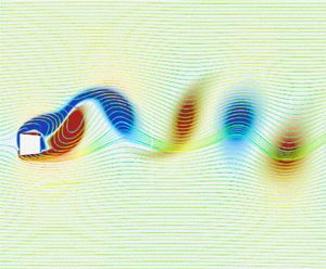
Figure 14 exhibits the contours of the vorticity field for a flow past a trapezoidal body with the windward interior angle of $89^{\circ }$ at $(Re,m^*) = (160, 10)$ for various values of the reduced velocity $U_r$ that span regimes from desynchronization to galloping. Overall, the wake dynamics before the FIV system enters into the galloping regime mainly display the 2S pattern. The values of $U_r = 10$ and 12 correspond to the desynchronization regime for the FIV system and the WM is associated with a typical 2S pattern of vortex shedding. When $U_r$ reaches a value of 14, the system enters into the galloping regime. It is noted that the associated reduced natural structural frequency in the galloping regime is much smaller than the original vortex-shedding frequency and, as a result, the behaviour of the vortex shedding is no longer locked into the natural structural frequency. In this case, the moving body can be regarded simply as a moving source of vortex shedding and, owing to the relatively slow speed of motion of the body, the vortex-shedding pattern is similar to the vortex-shedding pattern in the desynchronization regime, except for the fact that the contours of the vorticity field are slightly deformed. The pattern is spatially displaced as a whole in the transverse direction as the body moves. This kind of wake behaviour is regarded as the $m$S + $n$S mode, and $m + n \geqslant 5$ for the galloping regime (Seyed-Aghazadeh et al. Reference Seyed-Aghazadeh, Carlson and Modarres-Sadeghi2017; Zhu et al. Reference Zhu, Tang, Gao, Zhou and Wang2021; Chen et al. Reference Chen, Ji, Alam, Xu, An, Tong and Zhao2022). Although the structural amplitude of the trapezoid concerned in figure 14 is not as significant as that of the $D$ section and triangular bodies for the same $U_r$ (or, vibration frequency), a perusal could help to determine the wake at $U_r = 25$ as the $5\textrm {S}+5\textrm {S}$ pattern (cf. with the marks in figure 14).

Figure 14. Contours of the vorticity field for a flow past a trapezoidal body with the windward interior angle of $89^{\circ }$ at $(Re,m^*) = (160, 10)$ for various values of the reduced velocity $U_r$.

The local stability of the FIV system is known to be influenced by structural damping, hence, the effect of structural damping on galloping triggering is further explored here. It is mentioned above that the isosceles trapezoid with a windward interior angle of ${>}90^{\circ }$ does not produce galloping when the structural damping is 0, therefore, further increasing the damping will make the structure more stable (or, galloping will not be produced). In this case, we choose the square cylinder here to test the critical effect of structural damping on galloping, since the square cylinder is the geometric tipping point for galloping triggering. As shown in figure 15, the FIV configuration consisting of the square cylinder with ($Re, m^*, U_r$) fixed at (160, 10, 30), and the structural damping coefficient $\zeta (=c/2\sqrt {km})$ decrease abruptly with time during calculation (annotated at the top of the panel). It is observed that the small fluctuations of the structural displacements are gradually obvious as $\zeta$ keeps getting smaller. Specifically, when $\zeta$ decreases to 0.05, the structure becomes unstable, the amplitude increases and galloping is generated. This implies that there is a threshold in the presented effect of a tiny interior angle change (low to 1$^{\circ }$) on the galloping trigger. In spite of this, the relationship between the tendency of contraction/expansion and the occurrence of galloping proposed in this paper is still valid. It is noted again that the structural damping still keeps vanishing in the previous as well as in the later analysis of the present work.

Figure 15. Time series of the normalized transverse displacement $y/D$ obtained for the FIV system consisting of the flow past a square cylinder at $(Re, m^*, U_r) = (160,10,30)$ with structural damping varying abruptly in time (in accordance to the sequence of values shown along the top of each panel).

5. Initial stage in triggering process of galloping

Here we outline a method to depict and analyse the structural instability in the galloping triggering process by using the idea of ‘time-energy evolution’. The instability encountered by the structure submerged in the fluids is owing to the fluid–structure interaction effect, accompanied by the energy transfer between the elastic system and the surrounding flow. Over a fixed-width time domain ($t-n\Delta t, t+n\Delta t$) spanning one specific time point $t$, the average normalized energy $E^*(t)$ extracted from fluids to the elastic system is defined as

(5.1)\begin{equation} E^*(t)=\frac{1}{2n}\int_{t-n\Delta t}^{t+n\Delta t}C_L(t)\dot{y}^*(t)\,\text{d}t . \end{equation}

Regarding one FIV system with zero structural dampings, previous research indicated that positive and negative values of $E^*$ are associated with the amplified and suppressed oscillation amplitude, respectively, whereas the stationary state is maintained at $E^* = 0$ (Morse & Williamson Reference Morse and Williamson2009; Menon & Mittal Reference Menon and Mittal2019; Zhu, Su & Breuer Reference Zhu, Su and Breuer2020; Menon & Mittal Reference Menon and Mittal2021). Unlike the lock-in behaviour where both the structural and kinetic responses are relatively regular (accompanied by a single peak in the spectrum), the structural vibration of galloping brings a more complex kinetic response (accompanied by multi peaks in the spectrum). As a result, the energy conversion in a single vibration cycle is not representative. In this paper our study will disregard the energy conversion in one vibration cycle as the criterion of evaluation in previous studies but will be based on the average energy conversion in multiple vibration cycles. The value of $n$ is chosen as 60 and 600 for the lock-in and galloping regimes herein, respectively.

Figure 16 displays the ‘time-energy evolution’ in which the upper two panels depict the real-time structural displacement changes with continuously varying $U_r$, and the bottom two panels show the average normalized energy $E^*(t)$ varying as a function of $t$ (or, with varying $U_r$). The simulation was conducted with the reduced velocity $U_r$ changing abruptly in time. The normalized time range of $(1200, 1500)$ corresponds to the lock-in regime with $U_r = 6$, whereas those of $(3000, 3800)$, $(3800, 4500)$ and (4500, —) are affiliated with the galloping regime with $U_r = 14$, 16 and 18, respectively. The data associated with lock-in and galloping phenomena are marked with ‘blue’ and ‘red’ colours, respectively, whereas the desynchronization regime is stained by a ‘black’ colour. The corresponding inset plot in each panel provides a closer view of the instability developing process of the FIV system transferring from desynchronization to the lock-in and/or galloping regimes. In the initial stage of the instability developing process at $U_r = 6$, the structural amplitude gradually amplifies accompanied by positive $E^*$. As the elastic system thereby achieves the limit-cycle situation, the $E^*$ returns to near zero. This indicates that the energy transfer between the elastic system and the fluid reaches a stable equilibrium during the periodic vibration of the structure in the background of the limit cycle. In vast contrast, the escaping process of the FIV system from lock-in to desynchronization regime is accompanied by negative $E^*$, implying that the fluid field absorbs energy from the elastic system. It is presented from the above discussion that for the FIV system of trapezoidal bodies with an internal angle of 91$^{\circ }$, the structural response completes the transfer from desynchronization to the galloping regime during the increase of $U_r$ from 12 to 14. Indeed, it is observed that the absolute value of $E^*$ maintains a tiny value at $U_r = 12$, implying that the energy transfer between fluids and the elastic system is weak. The galloping triggering process starting from $tU_0/D$ of 3000 is accompanied by a large amount of energy absorption by the elastic system from the fluid, leading to the value increase of $E^*$. However, when the structural response in the galloping regime enters the limit-cycle status, unlike the lock-in behaviour, although the average value of $E^*$ is maintained near 0, the overall fluctuation is drastic and accompanied by switching between positive and negative values.

Figure 16. Time series of the normalized transverse displacement $y/D$ (a,b) and average normalized energy $E^*(t)$ (c,d) for the windward interior angle of 89$^{\circ }$. Two situations with the system transferring from desynchronization to lock-in and galloping regimes are depicted in the left and right panels, respectively.

Unlike the spectrum of structural vibration where the primary frequency is always locked by the structural natural frequency, the spectrum of the lift coefficient is more complicated for the galloping instability. More specifically, the frequency of structural vibration decreases as $U_r$ increases, and when the structural frequency is small enough to be far from the original vortex-shedding frequency, the vortex mechanism escapes from the complete locking of the structure frequency. As a result, the intense peak of the $C_L$ spectrum is thereby dominated by the original vortex-shedding frequency, and several complete vortex-shedding cycles occur in one complete cycle of structural vibrations. Besides this, the $C_L$ variation is still affected by structural vibration. Consequently, the variation of normalized energy $E^*(t)$ in the galloping regime will inevitably be affected.

However, we are still curious as to how the mechanism of force interactions between the fluid and solid makes such a small interior angle change have a strong effect on the structural response and directly determines whether galloping is generated or not. Next, we try to explore the critical evolution of forces in the initial stage of the galloping developing process from a more microscopic perspective. For this purpose, we designed a set of comparative calculations between 90$^{\circ }$ and 91$^{\circ }$, with the parameters of the FIV system kept identical for both shapes. When the FIV system achieves the equilibrium status at $U_r=10$, and the spring stiffness is suddenly reduced to make $U_r$ increase to 20, and then the evolution of the dynamics response is observed. The dimensionless displacement $Y$ and velocity $\dot {Y}$ of the structure as well as the lift coefficient $C_L$, and the overall force coefficient $C_A$ are depicted in figure 17(a). Here $C_A$ is defined as $C_L+ky/(\frac {1}{2}\rho U^2D)$, representing the coefficient of the overall combined force acted on the object in the transverse direction.

Figure 17. The triggering and suppression evolution of the galloping instability for a FIV system consisting of flow passing a trapezoidal body with the interior angle of (i) 90$^{\circ }$ and (ii) 91$^{\circ }$. Here $U_r$ is changed from 10 to 20 at $T = 1650$. Dynamics responses ($C_A, C_L, \dot {Y},Y$) and time-frequency spectrum are displayed in subfigures (a,b), respectively.

The displacement of the FIV will contain both components of the vortex-shedding frequency as well as the structural natural frequency owing to the combined effect of the shedding vortex as well as the mounted spring (Zhang et al. Reference Zhang, Li, Ye and Jiang2015; Cheng et al. Reference Cheng, Lien, Yee and Zhang2022). As can be observed in figure 11(c), the structural natural frequency (0.05 Hz) at $U_r = 20$ is much smaller than the original vortex-shedding frequency ($\approx$0.16 Hz). Thus, at the initial stage of the structure evolution at $U_r = 20$ for both 90$^{\circ }$ and 91$^{\circ }$ in figure 17(a), the displacements $Y$ (demarcated with the red line), besides being mainly influenced by the vortex shedding, both also exhibit a slight modulation corresponding to the structural natural frequency. For configuration of 91$^{\circ }$, this kind of modulation gradually disappears and the displacements are gradually dominated by the original vortex-shedding frequency. In complete contrast, the modulation plays an increasingly important role in the structural displacements for 90$^{\circ }$ and gradually pulls the structural displacements to larger amplitudes. This interpretation is also corroborated by the variation of the time-frequency spectrum in figure 17(b). The initial stages at $U_r = 20$ for configurations of 90$^{\circ }$ and 91$^{\circ }$ both involve two frequency components $f_{ osc}D/U_{0}$ of 0.05 and 0.16. In the case of the progressively aggravated component of $f_{ osc}D/U_{0} = 0.05$ for the 90$^{\circ }$ configuration, this frequency component fades away for 91$^{\circ }$, demonstrating the mechanism of modal competition (Li et al. Reference Li, Lyu, Kou and Zhang2019; Cheng et al. Reference Cheng, Lien, Yee and Zhang2022).

A perusal of the structural displacements for 90$^{\circ }$ shows that the gradual amplification of the structural displacements is caused by the behaviour that a structural stroke length in one direction is accompanied by a shorter stroke length in the opposite direction that follows. The continuous superposition of this behaviour causes increasing structure destabilization. We select several specific time points (marked by the red vertical lines in figure 17a) to study the dynamics evolution between those points. A close view of the change of $C_L$ (demarcated with the blue line) indicates that the vortex-shedding mechanism completes a complete cycle between $T_ 1$ and $T_ 4$. Meanwhile, the body motion moves upward and completes stroke 1 from $T_ 1$ to $T_ 3$, during which it passes through the structural equilibrium position at $T_ 2$. Following this, the system moves downward and completes stroke 2 from $T_ 3$ to $T_ 4$. It is obvious that the length of stroke 2 is shorter than that of stroke 1. The variation of displacement is determined by the velocity, and underpinning the velocity variation is the acceleration as well as the overall force acting on the body. Consequently, we could find that area 1 enclosed by the velocity envelope (demarcated with the yellow line) and $x$ axis among ($T_1, T_3$) is larger than area 2 among ($T_3, T_4$). This is because the overall force variation during the process from $T_ 3$ to $T_ 4$ changes more rapidly than that from $T_ 1$ to $T_ 3$ (viz., with $C_A(T_4) > C_A(T_1)$), resulting in area 2 being smaller than area 1 and the length of stroke 2 being smaller than the length of stroke 1. In marked contrast, for a trapezoid body with a windward internal angle of 91$^{\circ }$ (cf. with the bottom panel), even if the length of stroke 2 (from $T_ 3$ to $T_ 4$) is shorter than that of stroke 1 (from $T_ 1$ to $T_ 3$), the length difference is not comparable to that of 90$^{\circ }$. Consequently, with the initial impulse of stiffness change, the trapezoidal bodies with windward interior angles of 90$^{\circ }$ (square cylinder) and 91$^{\circ }$ gradually demonstrate significantly different structural responses.

The contour of pressure coefficients and vorticity at $T_ {1,2,3,4,5}$ for the windward interior angles of 90$^{\circ }$ (square cylinder) are shown in figure 18. Comparative observation of the first and second columns of the panel reveals that the vortex location will also be the centre of the negative pressure region. Alternating shedding vortices on the upper and bottom sides of the column are accompanied by the alternating formulation of negative pressures. Those negative pressure areas acting on the surface of the object will result in a periodically varying fluid force. In addition, as can be observed in figure 18, it is difficult for the vortex dislodged from the two corners of the windward side of the square column to reattach to the geometric surface. It could be further deduced intuitively from the physical point of view that for isosceles trapezoids with smaller windward interior angles (${<}90^{\circ }$), the vortex reattachment is more difficult. In contrast, vortex reattachment on the upper and lower surfaces is prone to appear for geometries with a tendency to expand, and it will be expected that this vortex reattachment behaviour facilitates the dynamic stability of the elastically mounted structure. This conjecture should be further verified by designing special configurations of geometries in the future.

Figure 18. Contour of pressure coefficients and vorticity at $T_ {1,2,3,4,5}$ (demarcated in figure 17a) for a FIV system consisting of flow passing a trapezoidal body with the interior angle of 90$^{\circ }$ (square cylinder).

6. Modal analysis

In this section we first try to apply the widely used Den Hartog stability criterion (Den Hartog Reference Den Hartog1956) to explore the observed critical geometrical effect in this study. A detailed introduction to the Den Hartog stability criterion is given in Appendix A. The base flow for one specific configuration is obtained as in the above in the ERA identification (cf. with the first step in figure 4) and applied here for obtaining $C_L$ and $C_D$ to avoid the dynamics coefficients’ fluctuations. Figure 19 summarizes the stability characteristics for the FIV system consisting of a flow past an elastically mounted isosceles-trapezoidal body at $Re = 160$ for various values of the windward interior angle. Interestingly, it is observed that the absolute values of $dC_L/d \alpha$ and $C_D$ both become smaller with increasing windward interior angles. However, the Den Hartog function $H(\alpha )$ ($= -\textrm {d}C_L/\textrm {d}\alpha + C_D$) at $\alpha = 0^{\circ }$ is negative for the concerned trapezoidal bodies regardless of the value of the windward interior angle (implying the body exhibits a galloping instability that does not depend on the windward interior angle). The quasi-steady stability analysis here is inaccurate as it has been shown above that a galloping instability does not occur for the isosceles-trapezoidal body with a windward interior angle of $91^{\circ }$ and $95^{\circ }$ (in contradistinction to predictions provided by the Den Hartog stability criterion). Nevertheless, the increasing trend of the $H(\alpha )$ value does demonstrate that the system is becoming more stable with increasing windward interior angle. Although the Den Hartog stability criterion has been successfully applied previously for the $D$-section and isosceles-triangular bodies (Zhao et al. Reference Zhao, Hourigan and Thompson2018), it cannot be used to assess the system stability for the isosceles-trapezoidal body and especially with respect to how very small variations in the geometry of the body (e.g. windward interior angle) affect the stability (and, more specifically, whether galloping occurs). This section thereby focuses on investigating the mechanism underlying the above-introduced problems from the modal point of view using the ERA-based data-driven model.

Figure 19. The lift $C_L$ and drag $C_D$ coefficients for the base flow past an elastically mounted isosceles-trapezoidal body at $Re = 160$ for various values of the windward interior angle. The body is oriented relative to the incident wind direction with a rotation angle $\alpha = -1^{\circ }$ and $1^{\circ }$. The Den Hartog function $H(\alpha )$ is provided for a rotation angle of $\alpha = 0^{\circ }$.

Figure 20. The predictions of the $C_L$ impulse response obtained using FOM/CFD and the corresponding ROM/ERA at $Re = 20$, 45 and 60 for a square cylinder (symbols displayed correspond to every tenth point in the ROM/ERA response). The cases at $Re = 20$ and 45 correspond to stable wake flows, whereas that at $Re = 60$ corresponds to an unstable wake flow. The lower panel displays an expanded view of the temporal development of the $C_L$ impulse response over the first 20 time steps.

To construct one coupled state-space form for the FIV system, the accurate flow ROM needs to be obtained in advance as introduced in § 2.2. With respect to the flow passing a square cylinder (or, isosceles-trapezoidal body with interior angles of 90$^{\circ }$), the impulse response of $C_L$ (arising from imposing an impulse input signal on the normalized transverse displacement $h = u^\delta$) is shown in figure 20. This impulse response was obtained from FOM/CFD over 1000 time steps and from the corresponding ROM/ERA over 700 time steps. There is a very good agreement in the impulse response obtained from the FOM and the ROM. Moreover, the system identification method based on ROM/ERA has a high predictive accuracy for the time development of the dynamic coefficient $C_L$ for both the stable and unstable behaviours in the square cylinder wake. In particular, the first 20 time steps obtained from both FOM/CFD and ROM/ERA at $Re = 20$, 45 and 60 are shown in the right panel of figure 20, demonstrating that there is excellent conformance between these two predictions.

Figure 21(a) shows the root loci for a FIV system consisting of the flow past an elastically mounted isosceles-trapezoidal body at $(Re,m^*)=(160,10)$ for windward interior angles of $85^{\circ }$, $89^{\circ }$, $90^{\circ }$, $91^{\circ }$ and $95^{\circ }$. The results were obtained from a ROM/ERA of the FIV system. The solid red points are correlated to the stationary case of corresponding geometries. A perusal of the figure shows that even small changes around the balance ($90^{\circ }$) of contraction/expansion trend has significant effects on the trajectory of the associated root loci. The root loci for the isosceles-trapezoidal body with windward interior angles of $85^{\circ }$, $89^{\circ }$ and $90^{\circ }$ imply that after leaving the resonance lock-in region with increasing values of $U_r$, the growth rate (characterized by Re$(\lambda )$) associated with the SM is positive, so the trapezoidal body here has an unstable SM that leads to a galloping instability. Moreover, we note that Re$(\lambda )$ for the SM associated with the trapezoidal body with a windward interior angle of $85^{\circ }$ is larger than that associated with the square cylinder (or, trapezoidal body with a windward interior angle of $90^{\circ }$). Hence, the structural amplification response of a trapezoidal body with a windward acute interior angle is faster than that with a right angle (viz., a square cylinder) and, in consequence, the former body geometry is more prone to exhibit large-amplitude oscillations in the response than the latter body geometry. Our FOM/CFD simulations shown in figure 11(a) provide further support for this assertion – here, it is seen that the normalized maximum transverse displacement $y_{max}/D$ for the trapezoidal body with a windward interior angle of $89^{\circ }$ is about two times larger than that for the square cylinder with a windward interior angle of $90^{\circ }$.

Figure 21. (a) The root loci and (b) the variation of the growth/decay rate $\textrm {Re}(\lambda )$ and eigenfrequency $\textrm {Im}(\lambda )/2{\rm \pi}$ as a function of $F_s$ for a FIV system consisting of the flow past an elastically mounted isosceles-trapezoidal body at $(Re,m^*) = (160,10)$ with windward interior angles of $85^{\circ }$, $89^{\circ }$, $90^{\circ }$, $91^{\circ }$ and $95^{\circ }$. The SM $\textrm {SM}_\textrm {c}$ that is hidden in the coupled WSMI/WSMII modes is demarcated with crossed open symbols. The dotted line corresponds to the relationship $f=F_s$. The solid red points represent the stationary situation of corresponding geometries.

As $U_r$ increases beyond the range of values associated with the resonance lock-in regime for the flow past an isosceles-trapezoidal body with a windward interior angle of $85^{\circ }$, $89^{\circ }$ and $90^{\circ }$, there will be a value of $U_r$ at which galloping will be initiated. The precise value of $U_r$ at which this occurs depends critically on the mode switching behaviour of $\textrm {SM}_\textrm {c}$. The locations at which mode switching occurs for the trapezoidal body with a windward interior angle of $85^{\circ }$ and $90^{\circ }$ are marked as $S_{85}$ and $S_{90}$ in the top panel of figure 21(b), respectively. The values of $U_r$ corresponding to the onset of galloping for the trapezoidal body with a windward interior angle of $85^{\circ }$ and $90^{\circ }$ are 8.5 and 16, respectively. The variation of the maximum transverse displacement (obtained using FOM/CFD simulations) for the trapezoidal body with a windward interior angle of $85^{\circ }$, shown in figure 12, suggests that the onset of galloping occurs at $U_r \approx 8$. Similarly, a perusal of figure 11(a) indicates that for the square cylinder, the onset of galloping occurs at $U_r = 17$. These results for the value of $U_r$ associated with the onset of galloping are generally consistent with those obtained using ROM/ERA. Interestingly, this result seems to contradict the assertion of Li et al. (Reference Li, Lyu, Kou and Zhang2019) that the use of LSA will lead to a significant underestimation of the value of $U_r$ associated with the onset of galloping. The discrepancy here would be expected to be owing to the fact that Li et al. (Reference Li, Lyu, Kou and Zhang2019) did not identify the correct structure-dominated mode in their LSA of the square cylinder. In more detail, it is supposed that Li et al. (Reference Li, Lyu, Kou and Zhang2019) treats a particular coupled mode (i.e. WSMI or WSMII) as a structural mode for all $U_r$ values and ignores the mode switching behaviour.

For an isosceles-trapezoidal body with a windward obtuse interior angle, the response of the FIV system is stable – even when the difference between the obtuse angle and a right angle is as small as either $1^{\circ }$ or $5^{\circ }$. An examination of figure 21(a) shows that the root loci associated with the isosceles-trapezoidal body with a windward interior angle of $95^{\circ }$ is located in the left half-side of the complex frequency plane over the entire range of values of the reduced velocity $U_r$ – so, the SM corresponds to a negative growth rate ($\textrm {Re}(\lambda ) < 0$). As a result, this trapezoidal body will exhibit a resonance lock-in region, but no flutter-induced lock-in or galloping. Moreover, a perusal of figure 21(b) shows that for the isosceles-trapezoidal body with a windward interior angle of $91^{\circ }$, the SM first transitions from a stable to an unstable state with increasing values of $U_r$ (or, equivalently, with decreasing values of $F_s$) and then switches back to a stable state at an even larger value of $U_r$ (viz., the transition back to the stable state occurs at $F_s \approx 0.025$). The ROM/ERA results here are at variance with the FOM/CFD simulations where it can be seen that the isosceles-trapezoidal body with a windward interior angle of $91^{\circ }$ does not appear to exhibit a galloping instability. In spite of this discrepancy, both the FOM/CFD and ROM/ERA results suggest that even a small increase in the windward interior angle of an isosceles-trapezoid body beyond a right angle (square cylinder) can greatly enhance the structural stability of the body, and the slight geometrical expansion trend will critically suppress the galloping instability. Additionally, as already mentioned, the effects of the geometrical contraction/expansion in the downstream direction that we have observed on the $D$ section, isosceles triangle, cylinder connected C, etc. are also verified in the case of specially designed trapezoidal cases in this paper. Therefore, we infer that geometries with an overall expansion tendency are more likely to stabilize due to the squeezing effect of the incoming flow.

7. Experimental validation at high Reynolds number

A set of experiments are also conducted to support our conjecture. All measurements were conducted in the low-speed wind tunnel of the Aeroelasticity Group at Duke University (cf. with figure 22a). As summarized in table 2 introducing the experimental parameters, the closed circuit wind tunnel has a cross-sectional test area of $0.75 \times 0.53\ \textrm {m}^2$ and a test section length of 1.52 m (cf. with figure 22b). The operating air speed ranges from 5 to $35\ \textrm {m}\ \textrm {s}^{-1}$ (error: $1\ \textrm {m}\ \textrm {s}^{-1}$), recorded by a hot wire located upstream of the test section. The bluff body used in the present measurements is produced via the three-dimensional printer located in the new Technology Engagement Center at Duke University. The measured trapezoidal bluff body has a span length of 0.728 m. Distinguished from the above calculations where the inner angle of an isosceles trapezoid varies only by 1$^{\circ }$ with respect to a square, this experiment increases the interior angle discrepancy to 10$^{\circ }$ (cf. with figure 22c) owing to the precision control of the three-dimensional printer machine tool. In spite of this, from the point view of practical engineering, the isosceles trapezoids with the interior angle of 100$^{\circ }$ could also be regarded as a small geometrical change from the square cylinder, and consequently, its FIV response could be used to validate our suggestions – the tiny geometrical variation from balanced status to expansion trend will suppress the galloping phenomenon whereas contraction trend amplifies the galloping instability. Both sides of the column are connected to the universal rollers (located outside of the wind tunnel) by a thin rod, and the rollers are supported on the groove on the slide bar with lubricant applied to the rollers and contact surfaces to reduce friction. The trapezoidal column is elastically mounted by four identical linear springs with each end linked by two springs, and the column motion is limited to the transverse ($y$) direction. An accelerometer (model: PCB Piezotronics J352C34) with the sensitivity of $(\pm 10\,\%)10.2\ \textrm {mV}\ (\textrm {m}\ \textrm {s}^{-2})$ is placed on the spanwise end of the column to measure the real time-series variation of structural response.

Figure 22. Diagram of wind tunnel measurements. (a) The trapezoidal cylinder in Duke University low-speed wind tunnel. The flow speed is determined by a hot wire, located upstream of the test section. (b) Schematic of the experimental configuration: the cylinder is supported by four springs and is restricted to moving in the transverse direction. An accelerometer is attached to one end of the cylinder to measure the structural response. (c) Two-dimensional schematic of the cross-section. Forward and backward orientations are tested.

Table 2. Measured parameters in the experiments.

The natural frequency and damping of the FIV system in the air are measured by conducting free decay tests individually without incident flow. The practical measured structural natural frequency $F_n^e$ (obtained by the test and displayed in table 2) of 11.2 Hz highly agrees with the calculated structural natural frequency $F_n^s (={1}/{2{\rm \pi} }\sqrt {{k}/{m}})$ of 11.7 Hz. It is noted that the effect of added mass is ignored herein owing to the large mass ratio. The structured damping ratio derived from the experimental test results is 0.0023.

Figure 23 shows the variation of the maximum amplitude with incident wind speed for both backward and forward orientation cases (left two panels) and the frequency spectrum of structural displacements for several specific wind speeds (right two panels). It can be seen from the two right panels that the structural vibration frequencies are locked by the structural natural frequency when the elastic system is located at the lock-in or galloping regime. In addition, the maximum amplitude response proves our conjecture. More specifically, the structure with a backward configuration, accompanied by the tendency of the shape to expand in the downstream direction, gradually stabilizes at high wind speeds. On the contrary, the forward configuration, accompanied by the geometrical contract tendency, displays a galloping characteristic and the maximum amplitude of the vibration increases continuously with rising wind speeds. In terms of the forward configuration, time histories of normalized structural displacement $y/D$ at inflow velocities of $7.1\ \textrm {m}\ \textrm {s}^{-1}$ (lock-in), $22.5\ \textrm {m}\ \textrm {s}^{-1}$ (desynchronization) and $39.8\ \textrm {m}\ \textrm {s}^{-1}$ (galloping) are exhibited in figure 23(c). The time-series response of lock-in and galloping contains, in addition to the component corresponding to the structural natural frequency, a weak modulation behaviour. The work presented herein shows that a contraction of the trapezoidal body in the streamwise direction (viz., in the direction of the incident wind) is correlated with the presence of a galloping instability, and this trend has also been experimentally seen for the $D$-section and isosceles-triangular bodies (Lian et al. Reference Lian, Yan, Liu, Zhang, Ren and Yang2017; Zhao et al. Reference Zhao, Hourigan and Thompson2018).

Figure 23. Maximum amplitude envelops and frequency spectrum of structural displacements for a FIV system consisting of wind passing the tested trapezoidal cylinder with a (a) backward and (b) forward orientation in measurements. (c) Time series of the structural displacement for the forward configuration at three representative reduced velocities.

8. Conclusion

In this paper detailed investigations were conducted to determine the mechanisms responsible for triggering galloping in a flow past an elastically mounted trapezoidal body, with a particular emphasis on the critical influence of the geometrical contraction and expansion on the initiation of galloping instability. Besides the experimental exploration, two numerical methodologies have been used to address this problem: namely, FOM/CFD simulations, and the application of data-driven stability analysis based on the use of a ROM obtained using the eigenvalue realization algorithm.

A novel result of the present paper concerns the fact that very small changes in the windward interior angle of an isosceles-trapezoidal body can have a significant effect on the appearance or disappearance of galloping in the case of the specific parameter setting of $(Re, m^*) = (160, 10)$. Using an isosceles-trapezoidal body with a windward interior right angle (square cylinder) as the reference, it was found that even a small increase in the value of the windward interior angle (say, from $90^{\circ }$ to $91^{\circ }$) can lead to a complete suppression of the galloping instability. Alternatively, a small decrease in the windward interior angle of an isosceles-trapezoidal body to a value below $90^{\circ }$ can result in a significant enhancement of the galloping oscillations.

We then analysed the detailed response of the initiation stage of the galloping triggering with the micro perspective and demonstrated that the gradual structural amplification is owing to the length differences of the adjacent strokes in the displacement variation. The continuous superposition of stroke length differences leads to galloping instability and the dominance of the structural nature frequency. From a macroscopic perspective, the geometry with an expansion trend in the streamline direction is prone to remain stable due to the squeezing effect of the incoming flow. Owing to the very large amplitude and very low frequency of the oscillations of the galloping regime, the vortex-shedding pattern corresponds to a slow transverse displacement of a $5\textrm {S}+5\textrm {S}$ mode (as if the 2S vortex pattern were frozen into the flow at any particular time in this spatial displacement).

The observation provided by FOM/CFD was supported by our data-driven stability analysis (and, more specifically, ROM/ERA). The variation of the windward interior angle of the trapezoid from 90$^{\circ }$ to 91$^{\circ }$ leads the structural-dominated mode SM${_\textrm {c}}$ to become stable in the large $U_r$ regime. This suggests that the presence of a certain tendency for whether the geometry contracts or expands in the streamline direction determines whether galloping occurs from the geometrical perspective. Additionally, these conclusions were also supported by our experimental measurements in the subsonic wind tunnel. We note that there still exists possible attempts to further validate the present hypothesis. Future work could be done investigating the difference in the galloping response between expansion and contraction tendencies for the geometries with smooth outlines (or without sharp corners).

Funding

The first author is supported by Natural Sciences and Engineering Research Council of Canada (NSERC). This work was made possible by the facilities of Aeroelasticity Group at Duke University, the Shared Hierarchical Academic Research Computing (SHARCNET), and Compute/Calcul Canada.

Declaration of interests

The authors report no conflict of interest.

Appendix A. Den Hartog stability criterion

Den Hartog (Reference Den Hartog1956, pp. 370–371) proposed a stability criterion to determine the potential susceptibility of a FIV system to develop a galloping behaviour from the equilibrium position. Figure 24 shows a bluff body that is moving in the downward direction (transverse to the incident flow $U$) and, as a result of this motion, the incoming flow $U_{rel}$ relative to the moving body is incident from below at an angle $\alpha = {\tan }^{-1}(v/U)$, where $v$ is the downward (transverse) velocity of the body.

Figure 24. The total fluid force acting on a downward-moving body can be resolved into two components: a lift force $F_L$ and a drag force $F_D$.

The lift $F_L$ and drag $F_D$ forces acting on the downward-moving body have $y$ components (opposite of the direction of the moving body) given by $F_L \cos \alpha$ and $F_D \sin \alpha$, respectively, which results in a total upward force $F_Y$ acting on the body that retards its downward motion:

(A1)\begin{equation} F_Y=F_L \cos\alpha +F_D \sin\alpha . \end{equation}

The condition for aerodynamically unstable behaviour for the moving (vibrating) body is given by

(A2)\begin{equation} \frac{{\rm d}F_Y}{{\rm d}\alpha} < 0 , \end{equation}

which, in view of (A1), can be recast in terms of the static force coefficients for a unit spanwise length as

(A3)\begin{align} \frac{{\rm d}F_Y}{{\rm d}\alpha}& =\cos\alpha \left( \frac{{\rm d}F_L}{{\rm d}\alpha}+F_D \right) + \sin\alpha \left(-F_L+\frac{{\rm d}F_D}{{\rm d}\alpha} \right) \nonumber\\ &\approx \left(\frac{{\rm d}F_L}{{\rm d}\alpha}+F_D\right) \nonumber\\ & =\frac{1}{2}\rho U^2D \left( \frac{{\rm d}C_L\left( \alpha \right)}{{\rm d}\alpha}+C_D\left( \alpha \right) \right) < 0 , \end{align}

where the penultimate line follows from the assumption that $\alpha \ll 1$ so $\cos \alpha \approx 1$ and $\sin \alpha \approx 0$. Here, $C_L$ and $C_D$ are the lift and drag coefficients, respectively, and $U$ is the flow speed.

From (A3), it is seen that a positive value for the derivative of the lift coefficient with respect to $\alpha$ corresponds to an aerodynamically stable behaviour for the vibrating body, whereas a negative value for the derivative of the lift coefficient with respect to $\alpha$ can potentially lead to an aerodynamically unstable behaviour for the body. The Den Hartog stability condition can only be used to assess the stable behaviour of a body with a specific shape at a certain angle of attack $\alpha$ and, from this perspective, the parameters that define the elastically supporting device that may be attached to the body are not taken into consideration. Clearly, the Den Hartog stability condition has limitations, and the above conducted analysis also clarifies some of these restrictions in the application of this stability criterion (based on a quasi-steady theory for addressing aerodynamic problems).

References

Billah, K.Y. & Scanlan, R.H. 1991 Resonance, Tacoma Narrows bridge failure, and undergraduate physics textbooks. Am. J. Phys. 59 (2), 118124.CrossRefGoogle Scholar
Bukka, S.R., Magee, A.R. & Jaiman, R.K. 2020 Stability analysis of passive suppression for vortex-induced vibration. J. Fluid Mech. 886, A12.CrossRefGoogle Scholar
Chen, S. 2004 Dynamic performance of bridges and vehicles under strong wind. PhD thesis, Louisiana State University, Baton Rouge, LA.Google Scholar
Chen, W., Ji, C., Alam, M.M., Xu, D., An, H., Tong, F. & Zhao, Y. 2022 Flow-induced vibrations of a D-section prism at a low Reynolds number. J. Fluid Mech. 941, A52.10.1017/jfm.2022.314CrossRefGoogle Scholar
Cheng, Z., Lien, F.-S., Yee, E. & Zhang, J.-H. 2022 Mode transformation and interaction in vortex-induced vibration of laminar flow past a circular cylinder. Phys. Fluids 34, 033607.10.1063/5.0080722CrossRefGoogle Scholar
Den Hartog, J.P. 1956 Mechanical Vibrations. McGraw–Hill.Google Scholar
Ding, L., Zhang, L., Wu, C., Mao, X. & Jiang, D. 2015 Flow induced motion and energy harvesting of bluff bodies with different cross sections. Energy Convers. Manage. 91, 416426.10.1016/j.enconman.2014.12.039CrossRefGoogle Scholar
Dullweber, A., Leimkuhler, B. & McLachlan, R. 1997 Symplectic splitting methods for rigid body molecular dynamics. J. Chem. Phys. 107 (15), 58405851.10.1063/1.474310CrossRefGoogle Scholar
Gao, C., Zhang, W., Li, X., Liu, Y., Quan, J., Ye, Z. & Jiang, Y. 2017 Mechanism of frequency lock-in in transonic buffeting flow. J. Fluid Mech. 818, 528561.10.1017/jfm.2017.120CrossRefGoogle Scholar
Hollenbach, R., Kielb, R. & Hall, K. 2021 Extending a Van Der Pol-based reduced-order model for fluid-structure interaction applied to non-synchronous vibrations in turbomachinery. Trans. ASME J. Turbomach. 144 (3), 031006.Google Scholar
Huang, H. & Li, X. 2013 Experimental study on the influence factors of static aerodynamic characteristics of ice-coated commonly used conductors. Adv. Mat. Res. 774–776, 12271231.Google Scholar
Jaiman, R.K., Sen, S. & Gurugubelli, P.S. 2015 A fully implicit combined field scheme for freely vibrating square cylinders with sharp and rounded corners. Comput. Fluids 112, 118.10.1016/j.compfluid.2015.02.002CrossRefGoogle Scholar
Johns, K.W. & Dexter, R.J. 1998 The development of fatigue design load ranges for cantilevered sign and signal support structures. J. Wind Engng Ind. Aerodyn. 77–78, 315326.10.1016/S0167-6105(98)00152-4CrossRefGoogle Scholar
Li, X., Lyu, Z., Kou, J. & Zhang, W. 2019 Mode competition in galloping of a square cylinder at low Reynolds number. J. Fluid Mech. 867, 516555.CrossRefGoogle Scholar
Lian, J., Yan, X., Liu, F., Zhang, J., Ren, Q. & Yang, X. 2017 Experimental investigation on soft galloping and hard galloping of triangular prisms. Appl. Sci. 7 (2), 198.10.3390/app7020198CrossRefGoogle Scholar
Mao, X., Zhang, L., Hu, D. & Ding, L. 2019 Flow induced motion of an elastically mounted trapezoid cylinder with different rear edges at high Reynolds numbers. Fluid Dyn. Res. 51 (2), 025509.10.1088/1873-7005/aaf832CrossRefGoogle Scholar
Menon, K. & Mittal, R. 2019 Flow physics and dynamics of flow-induced pitch oscillations of an airfoil. J. Fluid Mech. 877, 582613.CrossRefGoogle Scholar
Menon, K. & Mittal, R. 2021 On the initiation and sustenance of flow-induced vibration of cylinders: insights from force partitioning. J. Fluid Mech. 907, A37.10.1017/jfm.2020.854CrossRefGoogle Scholar
Mittal, S. 2008 Global linear stability analysis of time-averaged flows. Intl J. Numer. Meth. Fluids 58 (1), 111118.10.1002/fld.1714CrossRefGoogle Scholar
Modi, V.J. & Munshi, S.R. 1998 An efficient liquid sloshing damper for vibration control. J. Fluids Struct. 12 (8), 10551071.10.1006/jfls.1998.0182CrossRefGoogle Scholar
Morse, T.L. & Williamson, C.H.K. 2009 Prediction of vortex-induced vibration response by employing controlled motion. J. Fluid Mech. 634, 539.10.1017/S0022112009990516CrossRefGoogle Scholar
Nakamura, Y. & Tomonari, Y. 1977 Galloping of rectangular prisms in a smooth and in a turbulent flow. J. Sound Vib. 52 (2), 233241.10.1016/0022-460X(77)90642-3CrossRefGoogle Scholar
Navrose, & Mittal, S. 2016 Lock-in in vortex-induced vibration. J. Fluid Mech. 794, 565594.10.1017/jfm.2016.157CrossRefGoogle Scholar
Novak, M. & Tanaka, H. 1974 Effect of turbulence on galloping instability. J. Engng Mech. ASCE 100 (1), 2747.Google Scholar
OpenFOAM/v2006 2019 OpenCFD, User Guide v2006. Available at: https://www.openfoam.com/documentation/guides/latest/doc/.Google Scholar
Païdoussis, M.P., Price, S.J. & De Langre, E. 2010 Fluid-Structure Interactions: Cross-Flow-Induced Instabilities. Cambridge University Press.10.1017/CBO9780511760792CrossRefGoogle Scholar
Park, D. & Yang, K.S. 2016 Flow instabilities in the wake of a rounded square cylinder. J. Fluid Mech. 793, 915932.10.1017/jfm.2016.156CrossRefGoogle Scholar
Park, H., Kumar, R.A. & Bernitsas, M.M. 2013 Enhancement of flow-induced motion of rigid circular cylinder on springs by localized surface roughness at $3\times 10^4\leqslant Re \leqslant 1.2\times 10^5$. Ocean Engng 72, 403415.10.1016/j.oceaneng.2013.06.026CrossRefGoogle Scholar
Pippard, A. 1953 Behaviour of engineering structures. Nature 171, 766769.10.1038/171766a0CrossRefGoogle Scholar
Sanders, A.J. 2004 Non-synchronous vibration (NSV) due to a flow-induced aerodynamic instability in a composite fan stator. Trans. ASME J. Turbomach. 6, 507516.Google Scholar
Service, S. 1942 “Galloping Gertie” bridge. Science 95 (2462), 1010.Google Scholar
Seyed-Aghazadeh, B., Carlson, D.W. & Modarres-Sadeghi, Y. 2017 Vortex-induced vibration and galloping of prisms with triangular cross-sections. J. Fluid Mech. 817, 590618.10.1017/jfm.2017.119CrossRefGoogle Scholar
Shieh, L.S., Wang, H. & Yates, R.E. 1980 Discrete-continuous model conversion. Appl. Math. Model. 4 (6), 449455.10.1016/0307-904X(80)90177-8CrossRefGoogle Scholar
Tang, Y., Chi, Y., Sun, J., Huang, T.-H., Maghsoudi, O.H., Spence, A., Zhao, J., Su, H. & Yin, J. 2020 Leveraging elastic instabilities for amplified performance: spine-inspired high-speed and high-force soft robots. Sci. Adv. 6 (19), eaaz6912.10.1126/sciadv.aaz6912CrossRefGoogle ScholarPubMed
Tulsi, R.S., Mohd, F., Yashl, J. & Sanjay, M. 2019 Flow-induced vibration of a circular cylinder with rigid splitter plate. J. Fluids Struct. 89, 244256.Google Scholar
Waals, O.J., Phadke, A.C. & Bultema, S. 2007 Flow induced motions on multi column floaters. In ASME 2007 26th International Conference on Offshore Mechanics and Arctic Engineering, San Diego, California, USA, vol. 1: Offshore Technology; Special Symposium on Ocean Measurements and their Influence on Design, p. 669–678. ASME.10.1115/OMAE2007-29539CrossRefGoogle Scholar
Walker, A. & Sibly, P. 1977 The Tacoma bridge collapse. Nature 266, 675.10.1038/266675b0CrossRefGoogle Scholar
Wang, E., Xu, W., Gao, X., Liu, L., Xiao, Q. & Ramesh, K. 2019 The effect of cubic stiffness nonlinearity on the vortex-induced vibration of a circular cylinder at low Reynolds numbers. Ocean Engng 173, 1227.10.1016/j.oceaneng.2018.12.039CrossRefGoogle Scholar
Wang, S., Cheng, W., Du, R., Wang, Y. & Chen, Q. 2021 a Effect of mass ratio on flow-induced vibration of a trapezoidal cylinder at low Reynolds numbers. AIP Adv. 11 (7), 075215.10.1063/5.0057243CrossRefGoogle Scholar
Wang, S., Cheng, W., Du, R., Wang, Y. & Chen, Q. 2021 b Flow-induced vibration of a trapezoidal cylinder at low Reynolds numbers. Phys. Fluids 33 (5), 053602.10.1063/5.0047081CrossRefGoogle Scholar
Weaver, D.S. & Veljkovic, I. 2005 Vortex shedding and galloping of open semi-circular and parabolic cylinders in cross-flow. J. Fluids Struct. 21 (1), 6574.10.1016/j.jfluidstructs.2005.06.004CrossRefGoogle Scholar
Yao, W. & Jaiman, R.K. 2017 Model reduction and mechanism for the vortex-induced vibrations of bluff bodies. J. Fluid Mech. 827, 357393.10.1017/jfm.2017.525CrossRefGoogle Scholar
Zhang, B., Yang, X., Yang, W., Liu, B., Ai, W. & Ma, J. 2016 a The study on the applicability of aluminum conductor carbon core in the high incidence area of galloping for transmission lines. In 2016 IEEE International Conference on High Voltage Engineering and Application (ICHVE), Chengdu, China, p. 1–4. IEEE.10.1109/ICHVE.2016.7800927CrossRefGoogle Scholar
Zhang, J., Xu, G., Liu, F., Lian, J. & Yan, X. 2016 b Experimental investigation on the flow induced vibration of an equilateral triangle prism in water. Appl. Ocean Res. 61, 92100.10.1016/j.apor.2016.08.002CrossRefGoogle Scholar
Zhang, M, Øiseth, O., Petersen, Ø.W. & Wu, T. 2022 Experimental investigation on flow-induced vibrations of a circular cylinder with radial and longitudinal fins. J. Wind Engng Ind. Aerodyn. 223, 104948.10.1016/j.jweia.2022.104948CrossRefGoogle Scholar
Zhang, W., Li, X., Ye, Z. & Jiang, Y. 2015 Mechanism of frequency lock-in in vortex-induced vibrations at low Reynolds numbers. J. Fluid Mech. 783, 72102.10.1017/jfm.2015.548CrossRefGoogle Scholar
Zhao, J., Hourigan, K. & Thompson, M. 2019 An experimental investigation of flow-induced vibration of high-side-ratio rectangular cylinders. J. Fluids Struct. 91, 102580.10.1016/j.jfluidstructs.2019.01.021CrossRefGoogle Scholar
Zhao, J., Hourigan, K. & Thompson, M.C. 2018 Flow-induced vibration of D-section cylinders: an afterbody is not essential for vortex-induced vibration. J. Fluid Mech. 851, 317343.CrossRefGoogle Scholar
Zhao, J., Leontini, J.S., Lo Jacono, D. & Sheridan, J. 2014 Fluid-structure interaction of a square cylinder at different angles of attack. J. Fluid Mech. 747, 688721.CrossRefGoogle Scholar
Zhao, M. 2015 Flow-induced vibrations of square and rectangular cylinders at low Reynolds number. Fluid Dyn. Res. 47 (2), 025502.10.1088/0169-5983/47/2/025502CrossRefGoogle Scholar
Zhao, M., Cheng, L. & Zhou, T. 2013 Numerical simulation of vortex-induced vibration of a square cylinder at a low Reynolds number. Phys. Fluids 25 (2), 023603.10.1063/1.4792351CrossRefGoogle Scholar
Zhu, H., Tang, T., Gao, Y., Zhou, T. & Wang, J. 2021 Flow-induced vibration of a trapezoidal cylinder placed at typical flow orientations. J. Fluids Struct. 103, 103291.10.1016/j.jfluidstructs.2021.103291CrossRefGoogle Scholar
Zhu, Y., Su, Y. & Breuer, K. 2020 Nonlinear flow-induced instability of an elastically mounted pitching wing. J. Fluid Mech. 899, A35.10.1017/jfm.2020.481CrossRefGoogle Scholar
Figure 0

Figure 1. Forward and backward orientations of $D$ section and triangular shapes investigated in the FIV system.

Figure 1

Figure 2. Passive suppression devices investigated by Bukka et al. (2020) in one FIV system. (a) Cylinder-splitter plate. (b) Cylinder connected $C$.

Figure 2

Figure 3. Tiny geometrical changes from (b) square cylinder to (a,c) isosceles-trapezoidal shape will be investigated in the present work with respect to its effect on galloping stability in the FIV system. TL, transverse length of the body cross-section; SL, streamlined length of the body cross-section.

Figure 3

Figure 4. Flow diagram summarizing the five key steps in the workflow to obtain the ROM/ERA for a FIV system involving the coupling of a fluid dynamics ROM (with input $h$ and output $C_L$) to a structural dynamics model (with input $C_L$ and output $h$).

Figure 4

Figure 5. The computational domain used for the simulations of the flow past a bluff body elastically mounted on a linear spring. The prescribed boundary conditions on the flow velocity used in the simulations are shown.

Figure 5

Table 1. Aerodynamic coefficients (r.m.s. lift and drag coefficients) of flow past a stationary square cylinder at $Re = 100$ for four different meshes.

Figure 6

Figure 6. The fine mesh (mesh 3) used for the simulation of the flow past a square cylinder: (a) tessellation of the computational domain showing the overset and a partial background mesh surrounding the square cylinder; (b) close-up view of the overset mesh around the square cylinder; and (c) expanded view of the mesh in the immediate vicinity of the walls of the square cylinder.

Figure 7

Figure 7. The normalized maximum transverse displacement $y_{max}/D$ as a function of the reduced velocity $U_r$ of a FIV system consisting of the flow past an elastically mounted square cylinder at $(Re,m^*) = (150,10)$. The results were obtained using FOM/CFD and compared with results obtained by Li et al. (2019).

Figure 8

Figure 8. Distribution of the first 30 singular values of the Hankel matrix $H$ with $(r,s) = (500, 400)$ for flow past a backward isosceles-triangular body at $Re = 120$.

Figure 9

Figure 9. The growth rate as characterized by $\textrm {Re}(\lambda )$ of the first WM as a function of the Reynolds number $Re$. The current results for the growth rate of the first WM are compared with those reported by Li et al. (2019).

Figure 10

Figure 10. The root loci (parameterized by the reduced natural frequency $F_s = U_r^{-1}$) for the flow past a forward equilateral triangular cylinder elastically mounted on a linear spring at $(Re,m^*) = (60,10)$. This result is compared with that obtained by Yao & Jaiman (2017). The red solid square corresponds to the stationary body.

Figure 11

Figure 11. (a) Normalized maximum structural amplitude $y_{max}/D$, (b) r.m.s. value of the lift coefficient $C_{L, rms}$ and drag coefficient $C_{D, rms}$, (c) normalized structural oscillation frequency $f_{osc}D/U_0$ and (d) phase difference $\theta$ as a function of reduced velocity $U_r$. The lock-in regime for three interior angles and the galloping regime for windward interior angles $89^\circ$ are delineated with grey and red shading.

Figure 12

Figure 12. (a) Normalized maximum structural amplitude $y_{max}/D$, (b) r.m.s. value of the lift coefficient $C_{L, rms}$, (c) normalized structural oscillation frequency $f_{osc}D/U_0$ and (d) phase difference $\theta$ as a function of reduced velocity $U_r$. The lock-in regime for windward interior angles $95^\circ$ and the galloping regime for windward interior angles $85^\circ$ are delineated with grey and red shading.

Figure 13

Figure 13. Time series of the normalized transverse displacement $y/D$ obtained for a FIV system consisting of the flow past an elastically mounted isosceles-trapezoidal body at $(Re,m^*) = (160,10)$ with a windward interior angle of (a) $91^{\circ }$, (b) $85^{\circ }$ and (c) 95$^{\circ }$. For each configuration, the reduced velocity $U_r$ is changed (abruptly) in time in accordance to the sequence of values shown along the top of each panel.

Figure 14

Figure 14. Contours of the vorticity field for a flow past a trapezoidal body with the windward interior angle of $89^{\circ }$ at $(Re,m^*) = (160, 10)$ for various values of the reduced velocity $U_r$.

Figure 15

Figure 15. Time series of the normalized transverse displacement $y/D$ obtained for the FIV system consisting of the flow past a square cylinder at $(Re, m^*, U_r) = (160,10,30)$ with structural damping varying abruptly in time (in accordance to the sequence of values shown along the top of each panel).

Figure 16

Figure 16. Time series of the normalized transverse displacement $y/D$ (a,b) and average normalized energy $E^*(t)$ (c,d) for the windward interior angle of 89$^{\circ }$. Two situations with the system transferring from desynchronization to lock-in and galloping regimes are depicted in the left and right panels, respectively.

Figure 17

Figure 17. The triggering and suppression evolution of the galloping instability for a FIV system consisting of flow passing a trapezoidal body with the interior angle of (i) 90$^{\circ }$ and (ii) 91$^{\circ }$. Here $U_r$ is changed from 10 to 20 at $T = 1650$. Dynamics responses ($C_A, C_L, \dot {Y},Y$) and time-frequency spectrum are displayed in subfigures (a,b), respectively.

Figure 18

Figure 18. Contour of pressure coefficients and vorticity at $T_ {1,2,3,4,5}$ (demarcated in figure 17a) for a FIV system consisting of flow passing a trapezoidal body with the interior angle of 90$^{\circ }$ (square cylinder).

Figure 19

Figure 19. The lift $C_L$ and drag $C_D$ coefficients for the base flow past an elastically mounted isosceles-trapezoidal body at $Re = 160$ for various values of the windward interior angle. The body is oriented relative to the incident wind direction with a rotation angle $\alpha = -1^{\circ }$ and $1^{\circ }$. The Den Hartog function $H(\alpha )$ is provided for a rotation angle of $\alpha = 0^{\circ }$.

Figure 20

Figure 20. The predictions of the $C_L$ impulse response obtained using FOM/CFD and the corresponding ROM/ERA at $Re = 20$, 45 and 60 for a square cylinder (symbols displayed correspond to every tenth point in the ROM/ERA response). The cases at $Re = 20$ and 45 correspond to stable wake flows, whereas that at $Re = 60$ corresponds to an unstable wake flow. The lower panel displays an expanded view of the temporal development of the $C_L$ impulse response over the first 20 time steps.

Figure 21

Figure 21. (a) The root loci and (b) the variation of the growth/decay rate $\textrm {Re}(\lambda )$ and eigenfrequency $\textrm {Im}(\lambda )/2{\rm \pi}$ as a function of $F_s$ for a FIV system consisting of the flow past an elastically mounted isosceles-trapezoidal body at $(Re,m^*) = (160,10)$ with windward interior angles of $85^{\circ }$, $89^{\circ }$, $90^{\circ }$, $91^{\circ }$ and $95^{\circ }$. The SM $\textrm {SM}_\textrm {c}$ that is hidden in the coupled WSMI/WSMII modes is demarcated with crossed open symbols. The dotted line corresponds to the relationship $f=F_s$. The solid red points represent the stationary situation of corresponding geometries.

Figure 22

Figure 22. Diagram of wind tunnel measurements. (a) The trapezoidal cylinder in Duke University low-speed wind tunnel. The flow speed is determined by a hot wire, located upstream of the test section. (b) Schematic of the experimental configuration: the cylinder is supported by four springs and is restricted to moving in the transverse direction. An accelerometer is attached to one end of the cylinder to measure the structural response. (c) Two-dimensional schematic of the cross-section. Forward and backward orientations are tested.

Figure 23

Table 2. Measured parameters in the experiments.

Figure 24

Figure 23. Maximum amplitude envelops and frequency spectrum of structural displacements for a FIV system consisting of wind passing the tested trapezoidal cylinder with a (a) backward and (b) forward orientation in measurements. (c) Time series of the structural displacement for the forward configuration at three representative reduced velocities.

Figure 25

Figure 24. The total fluid force acting on a downward-moving body can be resolved into two components: a lift force $F_L$ and a drag force $F_D$.