Hostname: page-component-7bb8b95d7b-l4ctd Total loading time: 0 Render date: 2024-09-28T18:51:51.196Z Has data issue: false hasContentIssue false

Buckled elastic sheet as a vortex generator in dual channels

Published online by Cambridge University Press:  29 April 2024

Jingyu Cui*
Affiliation:
Zhejiang Key Laboratory of Multiphase Flow and Fluid Machinery, Zhejiang Sci-Tech University, Hangzhou 310018, PR China
Zhaokun Wang
Affiliation:
Department of Mechanical Engineering, The Hong Kong Polytechnic University, Kowloon, Hong Kong, PR China
Feng Ren
Affiliation:
School of Marine Science and Technology, Northwestern Polytechnical University, Xi'an 710072, PR China
Yang Liu
Affiliation:
Department of Mechanical Engineering, The Hong Kong Polytechnic University, Kowloon, Hong Kong, PR China
Weiwei Yan
Affiliation:
College of Metrology and Measurement Engineering, China Jiliang University, Hangzhou 310018, PR China
Yuzhen Jin*
Affiliation:
Zhejiang Key Laboratory of Multiphase Flow and Fluid Machinery, Zhejiang Sci-Tech University, Hangzhou 310018, PR China
*
Email addresses for correspondence: [email protected], [email protected]

Abstract

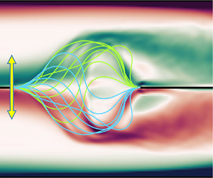
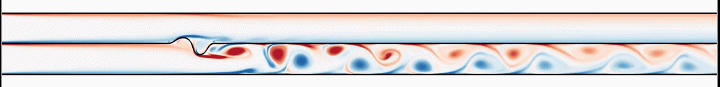
This study presents a dual-channel vortex generator (VG) that leverages the snap-through behaviour of flexible sheets. The VG outperforms a similar-sized rigid VG in generating vortices within dual-channel flows while minimizing pressure loss. Numerical simulations using the immersed boundary-lattice Boltzmann method analyse the dynamics and vortex generation performance of the sheet under various system parameters. Two distinct modes are identified for the elastic sheet: a sustained snap-through mode (SSTM) and a dormant mode (DM). The sheet's mode is predominantly influenced by its length ratio (L*), bending stiffness $(K_b^\ast )$ and flow strength, with the mass ratio having a minimal impact. The sheet exhibiting regular SSTM can effectively generate vortices in both channels and the vortex generation performance can be conveniently tuned by altering the sheet's initial buckling (i.e. L*). An increase in $K_b^\ast $ results in a higher critical Reynolds number (Rec) required for mode transition. An increase in L*, however, initially raises Rec and then lowers it, suggesting an optimal length ratio (approximately 0.7 for our considered system) for minimizing the Rec necessary to trigger SSTM. Furthermore, a disparity in the flow strength between channels is found to suppress the snap-through of the sheet; a greater disparity, however, is permissible to induce the SSTM of more compliant sheets. These findings underscore the potential of snap-through behaviour for enhanced flow manipulation in dual-channel systems.

Type
JFM Papers
Copyright
© The Author(s), 2024. Published by Cambridge University Press

1. Introduction

Enhancing flow mixing and improving heat transfer efficiency are desired across diverse industrial applications, including chemical processing, food industries, power generation, refrigeration and thermal management in electronic devices (Moore & Shi Reference Moore and Shi2014; Lee et al. Reference Lee, Wang, Liu and Fu2016; Cai et al. Reference Cai, Xue, Zhang and Lin2017; Zhang, Wang & Yan Reference Zhang, Wang and Yan2021; Liao & Jing Reference Liao and Jing2023a). Vortex generators (VGs) offer a practical approach to address these demands. By strategically placing these small devices on heat transfer surfaces, VGs generate vortices and modify flow characteristics. The induced vortices promote flow mixing, disrupting stagnant regions and promoting even fluid distribution over the heat transfer surface. This even distribution allows a larger portion of the surface to be actively involved in heat transfer, leading to efficient thermal exchange and minimized thermal gradients (Awais & Bhuiyan Reference Awais and Bhuiyan2018).

Numerous studies have investigated the effectiveness of different types of VGs in augmenting heat transfer in channel or pipe flows. Commonly used VGs comprise rigid structures affixed to wall surfaces, manifesting in diverse configurations, including ribs (Webb, Eckert & Goldstein Reference Webb, Eckert and Goldstein1971; Han, Glicksman & Rohsenow Reference Han, Glicksman and Rohsenow1978; Kim et al. Reference Kim, Kwak, Shin, Lee, Kim, Jung and Cho2011; Tanda Reference Tanda2011; Mahmoodi-Jezeh & Wang Reference Mahmoodi-Jezeh and Wang2020), fins (Jeong et al. Reference Jeong, Kim, Ha, Son, Lee and Kim2014; Zhao et al. Reference Zhao, Huang, Gong and Huang2016; Hussain et al. Reference Hussain, Freegah, Khalaf and Towsyfyan2019), twisted tapes (Bharadwaj, Khondge & Date Reference Bharadwaj, Khondge and Date2009; Bhattacharyya Reference Bhattacharyya2020) and delta winglets (He et al. Reference He, Han, Tao and Zhang2012; Zhou & Feng Reference Zhou and Feng2014; Akcayoglu & Nazli Reference Akcayoglu and Nazli2018; Skullong et al. Reference Skullong, Promthaisong, Promvonge, Thianpong and Pimsarn2018; Wu et al. Reference Wu, Liu, Yu, Liu and Liu2022b), among others. Each type induces unique flow patterns and enhances heat transfer through different mechanisms. Ribs and fins mounted on heat transfer surfaces disrupt the boundary layer and generate vortices, promoting heat transfer by increasing the turbulence intensity and enhancing convective heat transfer coefficients. Twisted tapes, however, are characterized by their helical shapes. They create swirl flows and induce secondary flow patterns, leading to enhanced heat transfer through improved mixing and disruption of the thermal boundary layer. Delta winglets, with their triangular shape, generate vortices and induce flow separation and reattachment. This enhances heat transfer by disrupting the boundary layer and improving convective heat transfer through increased fluid motion and thermal contact with the surface.

While rigid VGs offer significant benefits in enhancing flow mixing and heat transfer, they also have inherent shortcomings, such as limited flexibility, significantly increased pressure drop, higher energy consumption and reduced overall system efficiency (Promvonge & Thianpong Reference Promvonge and Thianpong2008). Flexible VGs, however, are promising alternatives due to their inherent flexibility or adaptability (Gallegos & Sharma Reference Gallegos and Sharma2017). Unlike rigid VGs, which are fixed structures, flexible VGs have the ability to deform, adjust or change their shape in response to varying flow conditions. These innovative devices harness the flapping motions of flexible structures to induce vigorous vortex shedding, promoting intense flow mixing and thereby enhancing convective heat transfer. The flexibility also empowers them to optimize flow disturbance and minimize flow resistance (Khatavkar et al. Reference Khatavkar, Anderson, den Toonder and Meijer2007; Lambert & Rangel Reference Lambert and Rangel2010; Chen et al. Reference Chen, Yang, Liu and Sung2020; Liao & Jing Reference Liao and Jing2023b). Shoele & Mittal (Reference Shoele and Mittal2014) introduced a novel method for generating vortices in a heated channel using a flexible reed. The reed was clamped at its leading edge while leaving the trailing edge free, resulting in a configuration known as the conventional flag model. This unique configuration demonstrates an exceptional thermal efficiency factor exceeding 120 %. Inverted flags clamped at the trailing edge (Park et al. Reference Park, Kim, Chang, Ryu and Sung2016; Yu, Liu & Chen Reference Yu, Liu and Chen2018; Chen et al. Reference Chen, Yu, Peng and Liu2019) have also been recognized as highly effective flexible VGs. Research has shown that the presence of inverted flags can lead to a remarkable 2.5-fold improvement in heat removal at a Reynolds number (Re) of 800, at the cost of an appreciable increase in pressure drop (Park et al. Reference Park, Kim, Chang, Ryu and Sung2016). Researchers have also explored the use of wall-mounted flags as VGs in channel flows. Lee et al. (Reference Lee, Park, Kim, Ryu and Sung2017) and Lee, Park & Sung (Reference Lee, Park and Sung2018) conducted numerical simulations to investigate the dynamics of a pair of wall-mounted flexible flags, and their effects on downstream vortical structures and heat transfer enhancement in a Poiseuille channel flow. Chen et al. (Reference Chen, Yang, Liu and Sung2020) extended this research by considering scenarios involving multiple wall-mounted flexible flags as VGs. In another study, Singh & Lakkaraju (Reference Singh and Lakkaraju2019) numerically characterized the flow behaviour when flexible plates were anchored to opposite walls of a channel. Their findings reveal that wall-mounted flexible plates induce early flow instabilities, resulting in enhanced flow mixing levels. These investigations contribute to a deeper understanding of using flexible flags/plates as VGs to enhance flow mixing and improve heat transfer in channel flows.

The snap-through phenomenon of elastic sheets has recently gained considerable attention (Cao et al. Reference Cao, Derakhshani, Fang, Huang and Cao2021). Snap-through refers to a phenomenon in which an elastic sheet undergoes a sudden and rapid transition from one stable configuration to another. This transition is characterized by a sudden change in shape and a significant release of stored energy within the sheet. It occurs when the applied load or deformation exceeds a critical threshold, causing the sheet to ‘snap’ or buckle into a new configuration. The snap-through behaviour of elastic sheets has found applications in various fields, including deployable structures (Bobbert, Janbaz & Zadpoor Reference Bobbert, Janbaz and Zadpoor2018; Arnouts et al. Reference Arnouts, Massart, de Temmerman and Berke2019; Yeow et al. Reference Yeow2021), robotics (Currier, Lheron & Modarres-Sadeghi Reference Currier, Lheron and Modarres-Sadeghi2020; Gorissen et al. Reference Gorissen, Melancon, Vasios, Torbati and Bertoldi2020; Dong et al. Reference Dong, Chen, Qiu, Yeow and Yu2022; Wu et al. Reference Wu, Baker, Yin and Zhu2022a), flow control (Gomez, Moulton & Vella Reference Gomez, Moulton and Vella2017; Jiao & Liu Reference Jiao and Liu2021; Zhang et al. Reference Zhang, Oseyemi, Ma and Yu2022) and energy harvesting devices (Qin et al. Reference Qin, Deng, Pan, Zhou, Du and Zhu2019; Zhou et al. Reference Zhou, Qin, Zhu, Du, Deng and Pan2019; Kim et al. Reference Kim, Zhou, Kim and Oh2020; Wang et al. Reference Wang, Zhou, Qin and Zhu2021, Reference Wang, Zhao, Fu, Deng, Zeng and Cui2023). By harnessing the abrupt configuration changes, engineers and researchers can exploit the unique properties and functionalities associated with snap-through behaviour to design innovative and efficient systems.

Prior research in vortex generator designs predominantly targeted single-channel structures. This study introduces a novel flexible VG that is specifically designed for dual-channel flow configurations. In contrast to traditional flapping flag-type VGs, the proposed design capitalizes on the snap-through behaviour of elastic sheets, offering exceptional capabilities for vortex generation and flow manipulation within dual-channel flows. This unique design enables rapid and reversible transitions between different stable configurations, leading to the creation of powerful vortices and enhanced flow disturbances in both channels. The dynamics of the sheet, the characteristics of vortex generation and the influence of governing parameters on the system are thoroughly investigated using numerical simulations. The concept may contribute to the advancement of flow control strategies and open new possibilities for optimizing flow characteristics in dual-channel flow configurations. The findings may shed light on the potential of using snap-through behaviour in elastic sheets as an effective means of achieving enhanced flow manipulation and vortex generation. The paper is organized as follows. Section 2 provides a description of the physical problem and outlines the methodology employed. In § 3, detailed results are presented, analysed and discussed. Finally, § 4 offers concluding remarks based on the findings.

2. Physical problem and methodology

2.1. Problem description

Figure 1 illustrates our proposed VG for dual channels. The dual channels considered in this study are symmetrical, sharing a middle dividing wall and possessing identical dimensions. Each channel has an identical width of H. A buckled elastic sheet with a length of L (L = 2H) is clamped at the mid-wall, functioning as a VG for the dual-channel system. The ends of the sheet are clamped parallel to the flow direction a distance of d apart, which also determines the sheet's initial buckling. The leading end of the sheet is located at a position Le downstream from the channel inlet. Two uniform flows of the same fluid enter the channels from the inlet with velocities U 1 and U 2, pass over the sheet, and leave from the outlet. When the flows reach sufficient strength, they can initiate a snap-through oscillation of the sheet, leading to the formation of vortices and significant flow disturbances downstream.

Figure 1. Schematic diagram for the dual channel-VG system. The sheet is initially buckled and clamped horizontally at the mid-wall of two identical channels. The sheet has a length of L when it is intrinsically straight and its end-to-end distance is d after buckling. The dimensions of the two channels are 12L in length and 0.5L in height.

In this study, the problem is considered in a two-dimensional (2-D) framework. It is assumed that all channel walls are rigid and there is no leakage at the walls or the sheet. Therefore, the fluids in the two adjacent channels are completely separated and they interact with each other only through the clamped elastic sheet. To begin with, the sheet is buckled downwards at equilibrium. Two observation points are respectively defined at the centreline of each channel to measure velocity fluctuations in the near and far wakes of the channels.

2.2. Mathematical formulation and numerical method

The flow is assumed to be incompressible and Newtonian in this study. Its governing equations are given as follows:

(2.1)\begin{gather}\boldsymbol{\nabla }\boldsymbol{\cdot }\boldsymbol{u} = 0,\end{gather}
(2.2)\begin{gather}\rho \left( {\frac{{\partial \boldsymbol{u}}}{{\partial \textrm{t}}} + \boldsymbol{u}\boldsymbol{\cdot }\boldsymbol{\nabla }\boldsymbol{u}} \right) =- \boldsymbol{\nabla }p + \mu \Delta \boldsymbol{u} + \boldsymbol{f},\end{gather}

where u = (u,v) is the flow velocity vector, p the pressure and f the body force term. The flow Reynolds number is defined as Re = ρHU/ $\mu$, where ρ is the fluid density and μ is the dynamic viscosity. Here, U represents the inlet velocity, which is U 1 for Channel 1 and U 2 for Channel 2. Additionally, H = 0.5L is the width of a single channel.

The sheet is assumed to be two-dimensional and thin. Its dynamics is governed by the following nonlinear partial differential equation (Connell & Yue Reference Connell and Yue2007; Hua, Zhu & Lu Reference Hua, Zhu and Lu2013):

(2.3)\begin{equation}{\rho _s}\frac{{{\partial ^2}\boldsymbol{X}}}{{\partial {t^2}}} = \frac{\partial }{{\partial s}}\left[ {Eh\left( {1 - {{\left( {\frac{{\partial \boldsymbol{X}}}{{\partial s}}\boldsymbol{\cdot }\frac{{\partial \boldsymbol{X}}}{{\partial s}}} \right)}^{ - 1/2}}} \right)\frac{{\partial \boldsymbol{X}}}{{\partial s}} - \frac{\partial }{{\partial s}}\left( {{K_b}\frac{{{\partial^2}\boldsymbol{X}}}{{\partial {s^2}}}} \right)} \right] + \boldsymbol{F},\end{equation}

where X is the position vector of the sheet and s is the Lagrangian coordinate along the sheet. The first and second terms on the right-hand side of the equation calculate the tensile force and bending force, respectively; Kb and Eh denote the bending and stretching stiffnesses of the sheet, respectively; F is the Lagrangian force exerted on the sheet by the neighbouring fluid and ρs is the linear density of the sheet.

Equations (2.1)–(2.3) are non-dimensionalized using the following characteristic scales: L for length, U 1 for velocity, L/U 1 for time, $\rho $ for density, $\rho L$ for linear density, $\rho U_1^2$ for pressure, $\rho U_1^2/L$ for force density, $\rho U_1^2{L^3}$ for bending stiffness and $\rho U_1^2L$ for stretching stiffnesses. The dimensionless forms of (2.1)–(2.3) are

(2.4)\begin{gather}{\nabla ^\ast }\boldsymbol{\cdot }{\boldsymbol{u}^{\boldsymbol{\ast }}} = 0,\end{gather}
(2.5)\begin{gather}\frac{{\partial {\boldsymbol{u}^{\boldsymbol{\ast }}}}}{{\partial {t^\ast }}} + {\boldsymbol{u}^{\boldsymbol{\ast }}}\boldsymbol{\cdot }{\nabla ^\ast }{\boldsymbol{u}^{\boldsymbol{\ast }}} =- {\nabla ^\ast }{p^\ast } + \frac{{0.5}}{{Re}}{\nabla ^{{\ast} 2}}{\boldsymbol{u}^{\boldsymbol{\ast }}} + {\boldsymbol{f}^{\boldsymbol{\ast }}},\end{gather}
(2.6)\begin{gather}{m^\ast }\frac{{{\partial ^2}{\boldsymbol{X}^{\boldsymbol{\ast }}}}}{{\partial {t^{{\ast} 2}}}} = \frac{\partial }{{\partial {s^\ast }}}\left[ {E{h^\mathrm{\ast }}\left( {1 - {{\left( {\frac{{\partial {\boldsymbol{X}^{\boldsymbol{\ast }}}}}{{\partial {s^\ast }}}\boldsymbol{\cdot }\frac{{\partial {\boldsymbol{X}^{\boldsymbol{\ast }}}}}{{\partial {s^\ast }}}} \right)}^{ - 1/2}}} \right)\frac{{\partial {\boldsymbol{X}^{\boldsymbol{\ast }}}}}{{\partial {s^\ast }}} - \frac{\partial }{{\partial {s^\ast }}}\left( {K_b^\ast \frac{{{\partial^2}{\boldsymbol{X}^{\boldsymbol{\ast }}}}}{{\partial {s^{{\ast} 2}}}}} \right)} \right] + {\boldsymbol{F}^{\boldsymbol{\ast }}},\end{gather}

where the quantities with an asterisk (*) represent their non-dimensional counterparts. Thus, we have the following dimensionless parameters for the sheet: the mass ratio ${m^\ast }\; = \; {\rho _s}/\rho L$, the bending stiffness $K_b^\ast= {K_b}/\rho U_1^2{L^3}$, the stretching stiffnesses $E{h^\ast } = Eh/\rho U_1^2L$ and the length ratio ${L^\ast } = d/L$, which defines the initial buckling of the sheet.

In the present study, the flow dynamics is solved by a multi-relaxation-time lattice Boltzmann model (MRT-LBM) due to its efficiency and parallelization (Kang Reference Kang2010; Wang et al. Reference Wang, Tang, Duan and Yu2016a,Reference Wang, Tang, Yu and Duanb, Reference Wang, Tang, Yu and Duan2017a,Reference Wang, Tang, Yu and Duanb; Wang & Tang Reference Wang and Tang2018, Reference Wang and Tang2019; Cui et al. Reference Cui, Wang, Liu, Jin and Zhu2022a). The evolution equation of the MRT-LBM with an external force term is given as

(2.7) \begin{align} &{f_\alpha }(\boldsymbol{x} + {\boldsymbol{e}_\alpha }\mathrm{\Delta }t,t + \mathrm{\Delta }t) - {f_\alpha }(\boldsymbol{x},t)\notag\\ &\quad =- {\boldsymbol{M}^{ - 1}}SM(\,{f_\alpha }(\boldsymbol{x},t) - f_\alpha ^{eq}(\boldsymbol{x},t)) - {\boldsymbol{M}^{ - 1}}\left( {\boldsymbol{I} - \dfrac{\boldsymbol{S}}{2}} \right)M{F_\alpha }(\boldsymbol{x},t)\Delta t ,\end{align}

where ${f_\alpha }(\boldsymbol{x},t)$ is the density distribution function of particles at position $\boldsymbol{x}$ and time t with velocity ${\boldsymbol{e}_\alpha }$; M is a transformation matrix and S is a non-negative diagonal relaxation matrix. Additionally, ${F_\alpha }(\boldsymbol{x},t)$ accounts for the effect of external forces and can be calculated by (Premnath & Abraham Reference Premnath and Abraham2007)

(2.8)\begin{equation}{F_\alpha }(\boldsymbol{x},t) = \frac{{[{\boldsymbol{e}_{\boldsymbol{\alpha }}} - \boldsymbol{u}(\boldsymbol{x},t)]\,\boldsymbol{f}(\boldsymbol{x},t)}}{{\rho c_s^2}}f_\alpha ^{eq}(\boldsymbol{x},t),\end{equation}

where cs is the model's speed of sound and $f_\alpha ^{eq}(\boldsymbol{x},t) = {\omega _\alpha }\rho [1 + \; {\boldsymbol{e}_\alpha }\boldsymbol{\cdot }\; \boldsymbol{u}/c_s^2 + {({\boldsymbol{e}_\alpha }\boldsymbol{\cdot }\; \boldsymbol{u})^2}/2c_s^4 - \; {\boldsymbol{u}^2}/2c_s^2]$ is the equilibrium distribution function with ${\omega _\alpha }$ being the weighting coefficients. The velocity u, mass density ρ and pressure p of the fluid can be calculated by

(2.9ac)\begin{equation}\rho = \sum\limits_\alpha {{f_\alpha }} ,\quad \boldsymbol{u} = {{\left( {\sum\limits_\alpha {{\boldsymbol{e}_\alpha }{f_\alpha }} + \frac{\boldsymbol{f}}{2}\mathrm{\Delta }t} \right)} / \rho },\quad p = c_s^2\rho .\end{equation}

The sheet is discretized into a collection of Lagrangian points that are uniformly distributed and its dynamics is solved using a finite-difference method (Huang, Shin & Sung Reference Huang, Shin and Sung2007; Yuan et al. Reference Yuan, Niu, Shu, Li and Yamaguchi2014). Specifically, the tensile force is computed at the centres of the segments, while the bending force is evaluated at the Lagrangian points. In our simulations, we use a sufficiently large Eh value to ensure that the sheet exhibits near inextensibility, with the maximal elongation rate controlled below 0.5 %.

The momentum-exchange-based immersed boundary method (IBM) is employed to handle the interaction between the fluid and the sheet. In this method, the hydrodynamic force exerted on the sheet is evaluated by (Niu et al. Reference Niu, Shu, Chew and Peng2006)

(2.10)\begin{equation}\boldsymbol{F}(\boldsymbol{X},t) = \sum\limits_\alpha {{\boldsymbol{e}_{\alpha \;}}[\,{f_\alpha }(\boldsymbol{X},t + \Delta t) - {f_{ - \alpha }}(\boldsymbol{X},t)]} ,\end{equation}

where $- \alpha $ denotes the opposite direction of $\alpha $ and ${f_\alpha }(\boldsymbol{X},t + \Delta t) = \int_\varOmega {f_\alpha }(\boldsymbol{x},t + \Delta t) \delta (\boldsymbol{x} - \boldsymbol{X}(\boldsymbol{s},t))\,\textrm{d}\kern0.06em x $ is the bounce-back distribution function of ${f_{ - \alpha }}(\boldsymbol{X},t)$. The reaction force of $\boldsymbol{F}(\boldsymbol{X},t)$ is spread to the nearby fluid points as follows to enforce the no-slip condition:

(2.11)\begin{equation}\boldsymbol{f}(\boldsymbol{x},t) = \int_\varGamma { - \boldsymbol{F}(\boldsymbol{X},t)\delta (\boldsymbol{x} - \boldsymbol{X}(s,t))\,\textrm{d}s} ,\end{equation}

where $\varGamma $ and $\varOmega $ denote the fluid and solid domains, respectively, and $\delta $ is the Dirac delta function (Peskin Reference Peskin2002; Yang et al. Reference Yang, Zhang, Li and He2009).

2.3. Output variables and boundary conditions

In our simulations, we specify a large value of Eh* to enforce the inextensibility condition of the sheet. When analysing the motion characteristics of the thin sheet, our focus will be on several dimensionless coefficients: lift coefficient (Cl), drag coefficient (Cd), kinetic energy coefficient $(E_b^\ast )$ and potential energy coefficient $(E_k^\ast )$. These coefficients are defined as follows:

(2.12ad)\begin{equation}{C_l} = \frac{{{F_l}}}{{0.5\rho U_1^2L}},\quad {C_d} = \frac{{{F_d}}}{{0.5\rho U_1^2L}},\quad E_b^\ast= \frac{{{E_b}}}{{0.5\rho U_1^2{L^2}}},\quad E_k^\ast= \frac{{{E_k}}}{{0.5\rho U_1^2{L^2}}},\end{equation}

where ${F_l}$ and ${F_d}$ are the lift and drag forces exerted on the sheet, while ${E_b} = 0.5{K_b}\int_0^L {{{({\partial ^2}X/\partial {s^2})}^2}\,\textrm{d}s} $ and ${E_k} = \textrm{0}\textrm{.5}{\rho _s}\int_0^L {{{(\partial X/\partial t)}^2}\,\textrm{d}s} $ represent the sheet's bending and kinetic energies.

When analysing the system's performance, the following statistically derived physical quantities will be considered:

(2.13)\begin{equation}\overline {{C_d}} ,\overline {E_b^\ast } ,\overline {E_k^\ast } ,\sigma ({C_l}),\sigma ({v^\ast }),\end{equation}

where $\overline {{C_d}} $, $\overline {E_b^\ast } $ and $\overline {E_k^\ast } $ represent the time-averaged values of Cd, $E_b^\ast $ and $E_k^\ast $, respectively; σ(Cl) and σ(v*) refer to the standard deviation of Cl and v*, respectively.

In this study, we strategically position the vortex generator near the channel inlet to maximize its effect on the downstream regions. Accordingly, our simulations implement a uniform velocity boundary condition at the channel inlets. The channel walls are subjected to a no-slip condition. At the channel outlet, we specify a pressure boundary condition to account for potential backflow. Oscillations of the sheet may result in volume fluctuations within each channel. The pressure boundary at the outlet can effectively addresses the potential compressibility issues arising from these fluctuations, as has previously demonstrated by Huang et al. (Reference Huang, Lai, Tian and Young2021) and Luo et al. (Reference Luo, Cai, Li and Pedley2008) in simulating incompressible flows in collapsible channels.

The sheet's end-to-end distance (d) is varied to change its initial buckling (i.e. the length ratio L* = d/L) in this study. However, with a given value for d, the initial buckled shape of the sheet remains unknown. To determine it, we first run the structural solver independently, applying a fixed boundary condition at one end of the sheet and a moving boundary condition at the opposite end (i.e. sliding the opposite end towards the fixed end). The fluid–structure interaction simulation is started after we obtain the initial buckled shape, during which the two ends of the sheet are imposed with a clamped boundary condition, i.e.

(2.14)\begin{gather}\boldsymbol{X} = \boldsymbol{X}(s,0),\quad \frac{{\partial \boldsymbol{X}}}{{\partial s}} = (1,0),\quad \textrm{at}\;s = 0,\end{gather}
(2.15)\begin{gather}\boldsymbol{X} = \boldsymbol{X}(s,0),\quad \frac{{\partial \boldsymbol{X}}}{{\partial s}} = ( - 1,0)\quad \textrm{at}\;s = L.\end{gather}

2.4. Numerical validations and grid independence study

The simulations were performed using our in-house code which has been thoroughly validated and verified in our previous studies (Cui et al. Reference Cui, Lin, Jin and Liu2019, Reference Cui, Wu, Liu, Fu, Jin and Zhu2022b; Cui, Liu & Jin Reference Cui, Liu and Jin2021). In our simulations, we set the Eulerian grid spacing Δx to be 1.5 times the Lagrangian grid spacing Δs (i.e. Δx = 1.5Δs). A grid independence study is conducted to ensure grid convergence, using the following system parameters: Re 1 = Re 2 = 1500, $K_b^\ast \; = \; 5 \times {10^{ - 3}}$, L* = 0.8, Le* = 3 and m* = 1. In each test case, the grid spacing is refined 1.5 times more than the coarser level. Additionally, the supporting range of the Dirac delta function is also expanded by 1.5 times to maintain a constant effective thickness of the sheet throughout each refinement (Wiens & Stockie Reference Wiens and Stockie2015). After comparing the pressure drop (Δp*), $\overline {{C_d}} $ and $\overline {E_b^\ast } $ across various grid resolutions (refer to table 1), we determined that the solution achieves grid independence when Δx = L/120.

Table 1. Results for the grid independence study at system parameter: Re 1 = Re 2 = 1000, $K_b^\ast= 5 \times {10^{ - 3}}$, L* = 0.8, Le* = 3 and m* = 1.

3. Results and discussion

This section presents, analyses and discusses the detailed results. We begin by analysing the sheet dynamics and vortex generation characteristics in a baseline case where the sheet undergoes a sustained snap-through oscillation. Subsequently, we investigate the influence of the bending stiffness $(K_b^\ast )$, length ratio (L*), mass ratio (m*) and sheet position (Le*) on the sheet dynamics and vortex generation. Lastly, we discuss the Reynolds number (Re) effect and determine the critical flow conditions required to initiate the snap-through oscillation of the sheet in two scenarios: whether Re 1 = Re 2 or Re 1 ≠ Re 2. Unless otherwise stated, it is assumed that the flows in the upper and lower channels have the same Re.

3.1. Sheet dynamics and vortex generation

In this study, two distinct modes are identified for the elastic sheet: a sustained snap-through mode (SSTM) and a dormant mode (DM). The SSTM is characterized by the sheet repeatedly snapping from one channel to the other at a relatively low frequency, as illustrated in supplementary movie 1 available at https://doi.org/10.1017/jfm.2024.244. This mode is self-excited, induced by a synergistic interaction between the sheet's motion and aero/hydrodynamic forces (Mao, Liu & Sung Reference Mao, Liu and Sung2023). DM involves the sheet exhibiting rapid yet minor vibrations within one channel without crossing the mid-wall of the dual channels, as shown in supplementary movie 2.

Figure 2(a) depicts the dynamics of the sheet in a typical snapping cycle. Both the sheet motion and the flow patterns exhibit a quasi-periodic state after 3–5 sheet oscillation cycles. The superimposed sheet profiles on the left are symmetrical about the line between the two clamped ends. The snapping cycle consists of two distinct stages: snap-up and snap-down. The snap-up stage begins with the sheet undergoing an upward stroke due to the generated transverse forces. During this process, the sheet's front half is observed to get transversely lifted before its rear half. The upward stroke is followed by a streamwise shift along the flow direction demonstrating the drag force of the fluid. Shortly after, there is an anti-streamwise movement driven by the restoring force generated within the sheet, seeking to bring the sheet back to its energy-minimized equilibrium position. These shifts occur swiftly, constituting only approximately 13 % of the entire cycle, and a rapid release and storage of bending and kinetic energies occur during these shifts, as depicted in figure 2(b). The stage concludes with damped oscillations of diminishing amplitude. Similarly, the snap-down stage follows the same pattern as snap-up, but starts with a downward stroke. The upward and downward strokes transpire at a relatively gradual pace, taking up approximately 70 % of the cycle's duration. Consequently, the time-averaged kinetic energy of the sheet $(E_k^\ast )$ over one cycle is considerably lower (nearly an order of magnitude lower) than the bending energy $(E_b^\ast )$. Prior to crossing the mid-wall, the sheet experiences a much slower transverse movement. Upon reaching and subsequently crossing the mid-wall, there is a sharp increase in the velocity of the transverse motion, which is accompanied by a rapid decrease in bending energy and a swift increase in kinetic energy (figure 2b).

Figure 2. (a) Sheet dynamics in a typical snapping cycle. Left: Superimposed sheet profiles throughout one snapping cycle. Right: Sequential presentation of the decomposed motion, highlighting the step-by-step progression. (b) Time evolution of the vertical coordinate of the sheet's midpoint $(Y_m^\ast )$, the sheet's bending energy $(E_b^\ast )$ and kinetic energy $(E_k^\ast )$ in an SSTM case. System parameters: Re 1 = Re 2 = 1000, $K_b^\ast= 5 \times {10^{ - 3}}$, L* = 0.75, Le* = 3 and m* = 1.

Figure 3 shows a series of snapshots highlighting the vortex structures and u-velocity contours for both our proposed VG and a comparably sized rigid sheet featuring a protruding profile. In the rigid-sheet scenario, vortices are intermittently formed, predominantly in the lower channel. In contrast, the elastic sheet dynamically generates a vibrant spectrum of vortices across both upper and lower channels (see supplementary movie 3), underscoring its heightened sensitivity and adaptability to fluid interactions (figure 3a). While the rigid sheet induces a fairly consistent flow with minimal disturbances, the elastic sheet, particularly when snapping, introduces a complex tapestry of velocity variations, suggesting its capability for more refined flow manipulations, as depicted in figure 3(b). A more qualitative analysis comparing the vortex generation capabilities of these two configurations can be found in table 2. Compared with the rigid counterpart, the elastic case augments the σ(v*) by an appreciable 17.6 % in the near-wake region and 5 % in the far-wake region. Moreover, the elastic case experiences a significant reduction in pressure drop, averaging 25.6 % overall and reaching 52.9 % in the lower channel. These findings highlight the potential advantages of incorporating the snap-through behaviour of elastic sheets in dual-channel systems for improved vortex generation and flow mixing.

Figure 3. (a) Vortex generation and (b) u-velocity contour for a rigid stationary sheet (top row) and a snapping elastic sheet (rows 2–6). System parameters: Re 1 = Re 2 = 1000, $K_b^\ast= 5 \times {10^{ - 3}}$, L* = 0.75, Le* = 3 and m* = 1.

Table 2. A comparison of the vortex generation performance between the elastic $(K_b^\ast= 5 \times {10^{ - 3}})$ and rigid sheets. Additional system parameters: Re 1 = Re 2 = 1000, L* = 0.75, Le* = 3 and m* = 1.

3.2. Effects of bending stiffness

We then analysed the influence of bending stiffness $(K_b^\ast )$ on the dynamics of the elastic sheet and its vortex generation performance. The bending stiffness was varied from $6.25 \times {10^{ - 4}}$ to $2 \times {10^{ - 2}}$, covering a range that allowed observation of diverse dynamical behaviours. This investigation was conducted with a fixed set of system parameters: Re 1 = Re 2 = 1000, L* = 0.75, Le* = 3 and m* = 1.

Figure 4 offers a detailed overview of the dynamic evolution of a buckled elastic sheet under various $K_b^\ast $ values. Varying the $K_b^\ast $ value reveals two distinct sheet modes: the SSTM occurs at $K_b^\ast \le 5 \times {10^{ - 3}}$ and the DM at $K_b^\ast \ge 1 \times {10^{ - 2}}$. The superimposed sheet profiles in figure 4(a) vividly illustrate the dynamic morphological changes of the elastic sheet at different $K_b^\ast $ values. With a low bending stiffness $(K_b^\ast= 6.25 \times {10^{ - 4}})$, the sheet is highly compliant, and thus demonstrates heightened sensitivity to the aero/hydrodynamical load. As a result, a chaotic and rather irregular snap-through oscillation is observed. Within a medium bending stiffness range $(1.25 \times {10^{ - 3}} \le K_b^\ast \le 5 \times {10^{ - 3}})$, the superimposed profiles of the sheet are more structured and symmetrically aligned. These are referred to as ‘regular snap-through oscillations’, which, as will be demonstrated later, are more favourable in vortex generations. Additionally, as shown in figure 4(b), an increase in the $K_b^\ast $ value results in a more pronounced bulbous central region. In the SSTM, there is a mild increase in the oscillation amplitude of $Y_m^\ast $ (A*) with rising $K_b^\ast $ values (figure 4b). The snapping frequency, however, initially increases and then decreases as $K_b^\ast $ increases (figure 4c), a pattern consistent with the numerical results of Mao et al. (Reference Mao, Liu and Sung2023) under uniform flow conditions. The turning point in this process occurs at $K_b^\ast= 1.25 \times {10^{ - 3}}$, beyond which the sheet exhibits regular snap-through oscillation (figure 4a). A higher snapping frequency is advantageous for achieving more synchronous flow mixing results between the two channels. Figure 4(d) shows how the average drag coefficient $(\overline {{C_d}} )$ and the standard deviation of the lift coefficient $(\sigma ({C_l}))$ vary with $K_b^\ast $, while figure 4(e) depicts the variation of the sheet's mean bending energy $(\overline {E_b^\ast } )$ and mean kinetic energy $(\overline {E_k^\ast } )$ with changes in the $K_b^\ast $ value. As $K_b^\ast $ increases, both $\overline {{C_d}} $ and $\overline {E_b^\ast } $ rise, whereas σ(Cl) and $\overline {E_k^\ast } $ exhibit a decline. Combining the trends presented in figure 4(be), an increase in A* correlates with an increase in both $\overline {{C_d}} $ and $\overline {E_b^\ast } $, which in turn can lead to enhanced mixing effects, as will be elucidated in subsequent discussions. The variation in σ(Cl) primarily influences the sheet's oscillation frequency and an increase in σ(Cl) leads to a rise in $\overline {E_k^\ast } $, which, in turn, affects the synchrony of the mixing effects between the channels. From figures 4(b) and 4(d), it is also found that when the sheet operates in the DM, it exhibits much lower values of A* and σ(Cl), and significantly higher values of $\overline {{C_d}} $ compared with those in the SSTM.

Figure 4. Sheet dynamics and associated metrics for varied $K_b^\ast $ values. (a) Sequentially superimposed sheet profiles, demonstrating morphological changes across different $K_b^\ast $ values. (b) Variation of the oscillation amplitude of $Y_m^\ast $ (A*) across the range of $K_b^\ast $, delineating two regimes: SSTM and DM. (c) Snapping frequencies presented for the SSTM cases. (d) Plots of $\overline {{C_d}} $ and σ(Cl) showing their dependence on $K_b^\ast $. (e) Energy metrics, $\overline {E_b^\ast } $ and $\overline {E_k^\ast } $, plotted against $K_b^\ast $. Relevant system parameters: Re 1 = Re 2 = 1000, L* = 0.75, Le* = 3 and m* = 1.

We also evaluated the vortex generation and flow mixing characteristics of the VG at various $K_b^\ast $ values. Figure 5 shows the flow-field characteristics and some associated metrics from our simulations. In the dormant mode, the sheet generates vortices only in the lower channel, with barely any noticeable vortices and v-velocity (v*) in the upper channel. However, in the sustained snap-through mode, the sheet produces equivalent vortex generation and v* distribution in both channels, as shown in the time-averaged flow information in figure 5(a,b). The fluctuations of the v-velocity (σ(v*)) at selected downstream positions (as referenced in figure 1) are illustrated in figure 5(c), where a higher σ(v*) value indicates enhanced flow mixing. The observed trend is that the average σ(v*) value initially rises with increasing $K_b^\ast $ values, but subsequently drops as the sheet transitions from SSTM to DM. When $K_b^\ast $ is within the range of $1.25 \times {10^{ - 3}}$ to $5 \times {10^{ - 3}}$, the average σ(v*) value consistently exceeds that of the rigid case, suggesting that a sheet in regular SSTM can outperform a rigid VG in flow mixing. The optimal flow mixing performance, given our system parameters, occurs at $K_b^\ast= 2.5 \times {10^{ - 3}}$. At this bending stiffness, both the disturbance at the boundary layer (figure 5a) and the v-velocity (figure 5b) are maximized. Figure 5(d) shows the evolution of the pressure drop $\Delta {p^\ast }$ across the $K_b^\ast $ range, capturing the general flow resistance trends in relation to $K_b^\ast $. In the DM cases, the lower channel, which houses the sheet, experiences a significantly greater pressure drop (over 2.5 times) than the upper channel. In contrast, the SSTM cases show no substantial difference in pressure drops between channels. In terms of the average pressure drop across both channels, it increases as the $K_b^\ast $ value increases. Moreover, the dual channel with a sheet in SSTM displays a markedly reduced average pressure drop compared with scenarios with the sheet in DM, underscoring another advantage of using a snap-through sheet as a vortex generator in dual-channel configurations.

Figure 5. Characteristics of the flow field and associated metrics for varied $K_b^\ast $ values. (a,b) Time-averaged vorticity field and v-velocity contours for select $K_b^\ast $ values. (c) Variation of v-velocity fluctuation σ(v*) in both the near- and far-wake regions of the upper and lower channels. Averaged trends for the near-wake and far-wake regions are indicated with short dashed lines. (d) Evolution of the pressure drop $\Delta {p^\ast }$ across the $K_b^\ast $ range. Accompanying system parameters: Re 1 = Re 2 = 1000 L* = 0.75, Le* = 3 and m* = 1.

3.3. Effects of length ratio

The length ratio (L*) is reported to play a pivotal role in influencing the snap-through oscillations of elastic sheets in a uniform flow (Kim et al. Reference Kim, Lahooti, Kim and Kim2021a; Mao et al. Reference Mao, Liu and Sung2023) and in the context of a single laminar channel flow (Wang et al. Reference Wang, Zhao, Fu, Deng, Zeng and Cui2023). In this study, we examined the impact of L* on the snap-through oscillations of elastic sheets in a dual-channel flow system, with a special focus on the sheet's vortex generation performance. The L* value was varied between 0.6 and 0.9, where a smaller L* value represents a more pronounced initial buckling and greater prestored bending energy. Other parameters considered in our analysis include Re 1 = Re 2 = 1000, $K_b^\ast= 5 \times {10^{ - 3}}$, Le* = 3 and m* = 1.

Figure 6 provides a comprehensive overview of how the dynamics of a buckled elastic sheet vary with different L* values. As the L* value increases, there is a notable decline in both the sheet's buckling degree and oscillation amplitude A* (as seen in figures 6a and 6b). Once L* exceeds 0.8, a transition from SSTM to MD occurs, resulting in a sharp decrease in A*. The oscillation behaviour almost disappears in the case L* = 0.9, where the sheet exhibits the least initial buckling. In figure 6(c), the snapping frequencies for the SSTM cases are depicted. The frequencies initially increase and then decrease, with the peak frequency occurring at a medium initial buckling of L* = 0.7. As will be discussed later, excessively large or small initial buckling inhibits the occurrence of sustained snap-through oscillation. Figures 6(d) and 6(e) show a nearly linear decline in both $\overline {{C_d}} $ and $\overline {E_b^\ast } $ as L* increases, underscoring their strong dependence on the sheet's initial buckling. Here, σ(Cl) and $\overline {E_k^\ast } $ evolve with a similar trend, indicating their strong correlation. Within the SSTM range, both σ(Cl) and $\overline {E_k^\ast } $ experience a first increase and then decrease trend as L* increases, and when the sheet transitions to DM, a conspicuous decrease in σ(Cl) and $\overline {E_k^\ast } $ is observable.

Figure 6. Sheet dynamics and associated metrics for varied L* values. (a) Sequentially superimposed sheet profiles. (b) Variation of A* across the range of L*, delineating two regimes: SSTM and DM. (c) Snapping frequencies presented for the SSTM cases. (d,e) $\overline {{C_d}} $, σ(Cl), $\overline {E_b^\ast } $ and $\overline {E_k^\ast } $, plotted against L*. Additional system parameters: Re 1 = Re 2 = 1000, $K_b^\ast= 5 \times {10^{ - 3}}$, Le* = 3 and m* = 1.

Figure 7 illustrates the vortex structures generated at some typical moments for various L* values. Increasing the initial buckling of the sheet (L* → 0) leads to enhanced vortex generation in the wake of the sheet: more intense vortices with more intricate patterns are observed in the downstream channel. Therefore, the vortex generation performance of the VG can be conveniently tuned by altering the sheet's initial buckling. The reason is that a sheet with more pronounced initial buckling protrudes further into the channels (as indicated in figure 6(b), where the oscillation amplitude A* increases with decreasing L* values), which is conducive to flow separation and vortex generation. In figure 7, the non-buckled-in channel exhibits developing vortices towards the computational domain's end, rather than the expected decaying ones. This suggests that the vortex intensity varies throughout the snap-through process, and weaker vortices are generated as the sheet is on the verge of a complete transition from one channel to another.

Figure 7. Vortex generation at different L* values. Additional parameters: Re 1 = Re 2 = 1000, $K_b^\ast= 5 \times {10^{ - 3}}$, Le* = 3 and m* = 1.

Figures 8(a) and 8(b) show the time-averaged flow field for various L* values, where increased initial buckling introduces greater disturbances in the boundary layer (figure 8a) and a larger vertical velocity component (v*) (figure 8b). The v-velocity fluctuation (σ(v*)) displayed in figure 8(c) demonstrates the flow mixing effect at the four observation points (figure 1). Compared with increasing the bending stiffness $K_b^\ast $, increasing the initial buckling of the sheet can more effectively boosts the vortex generation and flow mixing in dual channels: the average σ(v*) value increases by 17 times in the near wake and 4 times in the far wake when L* is reduced from 0.9 to 0.6. Note that the overall flow mixing effect in the dual channels is assessed by comparing the average σ(v*) values. However, it is important to note that this increased flow mixing is accompanied by a larger pressure loss, as depicted in figure 8(d).

Figure 8. Characteristics of the flow field and associated metrics for varied $K_b^\ast $ values. (a,b) Time-averaged vorticity field and v-velocity contours for select $K_b^\ast $ values. (c) Variation of v-velocity fluctuation σ(v*) in both the near- and far-wake regions of the upper and lower channels. Averaged trends for the near-wake and far-wake regions are indicated with short dashed lines. (d) Evolution of the pressure drop $\Delta {p^\ast }$ across the $K_b^\ast $ range. Additional system parameters: Re 1 = Re 2 = 1000, $K_b^\ast= 5 \times {10^{ - 3}}$, Le* = 3 and m* = 1.

3.4. Effects of mass ratio and sheet position

The impact of the mass ratio (m*) on the sheet dynamics and vortex generation was explored by varying m* values between 0.5 and 4.0. Additional system parameters, including Re 1 = Re 2 = 1000, $K_b^\ast= 5 \times {10^{ - 3}}$, Le* = 3 and L* = 0.75, were considered. Figure 9 displays the superimposed sheet profiles and associated metrics for various m* values. Our simulations revealed that varying m* from 0.5 to 4.0 does not trigger any mode transitions, indicating that the sheet mode is insensitive to the variations in mass ratio. This observation is consistent with the experimental findings of Kim et al. (Reference Kim, Lahooti, Kim and Kim2021). Furthermore, our results demonstrate that varying the mass ratio does not significantly impact the vortex generation results and pressure losses, as shown in figures 9(b) and 9(c). These findings suggest that the oscillation and buckling behaviours of the sheet are primarily stiffness-driven phenomena. It appears that the effective stiffness of the sheet, influenced by the flow strength, the bending stiffness and initial buckling of the sheet, rather than its mass, plays a crucial role in determining the mode and vortex generation capacity of the sheet. The resistance to bending provided by the effective stiffness seems to be the primary mechanism through which the sheet dynamically interacts with the fluid flow.

Figure 9. (a) Sequentially superimposed sheet profiles during a snapping cycle for different m* values. (b,c) $\overline {{C_d}} $, σ(Cl), $\overline {E_b^\ast } $ and $\overline {E_k^\ast } $, plotted against m*. (d,e) Variation of σ(v*) and $\Delta {p^\ast }$ with respect to m*. Additional parameters: Re 1 = Re 2 = 1000, $K_b^\ast= 5 \times {10^{ - 3}}$, Le* = 3 and L* = 0.8.

In practical applications like cooling electronic chips with a fan, VGs are typically positioned upstream to maximize their influence on the downstream flow. To elucidate the impact of the sheet's positioning on its dynamics and vortex generation performance, we varied the distance from the sheet's leading edge to the inlet, denoted as Le*, in our simulations. Additionally, for a comprehensive assessment, a simulation incorporating a parabolic inlet velocity profile was also conducted to draw comparisons with the uniform velocity inlet conditions (the mean inlet velocity remains constant between cases). Figure 10(a) illustrates the evolution of the boundary layer for Le* = 3. Figure 10(b) presents the superimposed sheet profiles at different Le* values (the parabolic velocity case can be interpreted as the sheet being positioned in a far downstream location where the flow is fully developed). Imposing a parabolic velocity at the inlet transitions the sheet to a dormant mode, highlighting the influence of the boundary layer on the sheet's dynamic behaviour: the developing boundary-layer profiles associated with a uniform velocity inlet exert significantly greater lift and drag forces on the elastic sheet positioned near the wall (figure 10d). This increased force can lead to a higher likelihood of the sheet becoming unstable and undergoing snap-through behaviour. However, increasing the Le* threefold, from 1.8 to 5.4, shows no significant change in the sheet's morphology (figure 10b), oscillation amplitude A* (figure 10c), drag coefficient $\overline {{C_d}} $ (figure 10d), v-velocity fluctuation σ(v*) (figure 10e) and pressure drop $\Delta {p^\ast }$ (figure 10f). This suggests that the flow boundary layer develops gradually in smooth channels, with the sheet's behaviour remaining relatively unaffected by minor variations in the boundary layer. For the SSTM cases, positioning the sheet further downstream increases both its snapping frequency and lift coefficient σ(Cl).

Figure 10. (a) Development of boundary layer when the sheet is placed at Le* = 3. (b) Sequentially superimposed sheet profiles, demonstrating morphological changes across different Le* values. (c) Variation of A* across the range of Le*, the inset plots the sheet's snapping frequency. (d) $\overline {{C_d}} $ and σ(Cl), plotted against Le*. (e) Variation of v-velocity fluctuation σ(v*) in both the near- and far-wake regions of the upper and lower channels. Averaged trends for near-wake and far-wake regions are indicated with short dashed lines. (f) Evolution of the pressure drop $\Delta {p^\ast }$ across the Le* range. Additional system parameters: Re 1 = Re 2 = 1000, $K_b^\ast= 5 \times {10^{ - 3}}$, L* = 0.75 and m* = 1.

3.5. The Reynolds number effect and critical flow conditions

Previous studies (Gomez et al. Reference Gomez, Moulton and Vella2017; Kim et al. Reference Kim, Lahooti, Kim and Kim2021a,Reference Kim, Kim and Kimb) have highlighted the significance of flow strength in initiating the snap-through oscillations of a buckled elastic sheet. In this section, we investigate the effect of Re and the critical flow conditions required to trigger SSTM in a dual-channel system. Figure 11 shows the impact of Re on the dynamic behaviour of a buckled elastic sheet and its associated metrics within a parametrized system defined by $K_b^\ast= 5 \times {10^{ - 3}}$, L* = 0.75, Le* = 3 and m* = 1. A shift from DM to SSTM is observed as Re transitions from 500 to 800, as illustrated in figure 11(a), underscoring the pivotal role of flow strength in governing the sheet mode. With an increase in Re, we note a limited increase in the oscillation amplitude A* within SSTM scenarios (figure 11b). The snapping frequency remains approximately constant, near 0.04 (figure 11c), indicating that the snapping amplitude and frequency are not sensitive to flow strength, at least within our considered Re range. An increase in Re correlates with an elevation in $\overline {{C_d}} $, σ(Cl) and $\overline {E_k^\ast } $ in SSTM cases (figure 11d,e). Conversely, a decrement in $\overline {E_b^\ast } $ is noted, which can be attributed to the more flattened sheet profiles generated at larger Re, as illustrated in figure 11(b). Figure 12 presents the flow field characteristics and correlated metrics across a range of Re, revealing that at higher Re, the VG produces more pronounced vortices and flow perturbations, yet it is associated with a reduced pressure drop. Therefore, the proposed VG demonstrates enhanced performance in higher-Re regimes.

Figure 11. Sheet dynamics and associated metrics for varied Re. (a) Sequentially superimposed sheet profiles. (b) Variation of A* across the range of Re, delineating two regimes: SSTM and DM. (c) Snapping frequencies presented for SSTM cases. (d,e) $\overline {{C_d}} $, σ(Cl), $\overline {E_b^\ast } $ and $\overline {E_k^\ast } $ plotted against Re. Additional system parameters: $K_b^\ast= 5 \times {10^{ - 3}}$, L* = 0.75, Le* = 3 and m* = 1.

Figure 12. Characteristics of the flow field and associated metrics for varied Re. (a,b) Time-averaged vorticity field and v-velocity contours. (c) Variation of v-velocity fluctuation σ(v*) in both the near- and far-wake regions of the upper and lower channels. Averaged trends for the near-wake and far-wake regions are indicated with short dashed lines. (d) Evolution of the pressure drop $\Delta {p^\ast }$ across the Re range. Additional system parameters: $K_b^\ast= 5 \times {10^{ - 3}}$, L* = 0.75, Le* = 3 and m* = 1.

Based on the above analysis, it is clear that the sheet mode is primarily influenced by three factors: its initial buckling L*, bending stiffness $K_b^\ast $ and the flow strength Re. Knowing the critical flow conditions of this system under different L* and $K_b^\ast $ values is crucial for its stability and performance optimization. We begin by examining a scenario where both the upper and lower channels have identical flow strengths (i.e. Re 1 = Re 2). In the study, the length ratio (L*) varies from 0.6 to 0.8 and the bending stiffness $(K_b^\ast )$ ranges from $1.25 \times {10^{ - 3}}$ to $6.25 \times {10^{ - 3}}$. Other parameters considered in our analysis include Le* = 3 and m* = 1.

Figures 13(a) and 13(b) depict the predicted sheet modes in the parameter spaces of Re–L* and $Re\unicode{x2013} K_b^\ast $, respectively. The dashed lines in these figures indicate the critical Reynolds number (Rec) necessary for mode transitions. It is apparent that Rec is significantly dependent on both L* and $K_b^\ast $. An increase in $K_b^\ast $ leads to a growth in Rec, suggesting that a higher flow strength is needed to initiate the SSTM of a stiffer sheet, particularly at larger $K_b^\ast $ values. This finding aligns with the results of Mao et al. (Reference Mao, Liu and Sung2023), where a uniform flow is considered. As L* increases, an initial decrease in the required Rec value is observed, reaching a minimum at L* = 0.7, after which it starts to increase, forming a ‘V’-shaped curve (figure 13a). This indicates that there exists an optimal initial buckling value at which the Rec needed to trigger snap-through oscillations of the sheet is minimized. This trend differs from the experimental observations by Kim et al. (Reference Kim, Lahooti, Kim and Kim2021), where Rec decreased monotonically with increasing L*. The discrepancy could be due to the smaller Reynolds numbers in our study and our sheet is positioned within or partially within the boundary layer. In the experimental set-up of Kim et al. (Reference Kim, Lahooti, Kim and Kim2021), higher-Reynolds-numbers flows were considered and their sheet was positioned centrally within a wider channel, thereby the boundary layer effect is minimized. In our simulations, when ${L^\ast } \le 0.7$, the sheet dynamics is predominantly influenced by the core region flow as the sheet protrudes greatly into the channels. Within this range, the bending energy stored or prestress within the sheet's structure reduces as L* increases. Consequently, a lesser fluid force suffices to overcome the prestress and initiate snap-through. This accounts for the observed decrement in Rec with increasing L*. However, for L* values above 0.7, the boundary layer's influence grows. With increasing L*, the sheet is situated increasingly closer to the sublayer of the boundary layer. Despite the reduction in prestress within the sheet, the fluid forces acting upon it diminish more rapidly, leading to an increment in Rec as L* increases. This complex interplay between the prestressed state of the sheet and the fluid dynamic highlights the sensitivity of snap-through phenomena to both the mechanical preconditions of the elastic medium and the characteristics of the surrounding flow field.

Figure 13. Sheet modes in the parameter spaces of (a) Re–L* ($K_b^\ast= 5 \times {10^{ - 3}}$, Le* = 3 and m* = 1) and (b) $Re\unicode{x2013} K_b^\ast $ (L* = 0.75, Le* = 3 and m* = 1). The dashed lines represent the critical Reynolds number (Rec) required to induce a mode transition. (c) Rec plotted in the parameter spaces of ${L^\ast }\unicode{x2013} K_b^\ast $ (Le* = 3 and m* = 1).

Figure 13(c) illustrates the predicted Rec value across the parameter space defined by the length ratio (L*) and the bending stiffness $(K_b^\ast )$, with the sheet position at Le* = 3 and the mass ratio fixed at m* = 1. It is observed that irrespective of the L* values surveyed, Rec increases with increasing bending stiffness and the increase in Rec is more pronounced at higher $K_b^\ast $ values. For the examined $K_b^\ast $ values, the required Rec values experience an initial escalation followed by a subsequent decline as L* increases, with the minimum Rec value obtained always at approximately L* = 0.7. Additionally, the impact of L* on Rec becomes more significant at higher $K_b^\ast $ values.

We then consider the scenario where the upper and lower channels exhibit different flow strengths (i.e. Re 1 ≠ Re 2). The flow strength of the lower channel is fixed at Re 1 = 1000, with a corresponding flow velocity U 1 = 0.012. The incoming flow velocity of the upper channel (U 2) is varied to obtain the desired velocity disparity U 1/U 2 between the upper and lower channels. In figure 14(a), we presented the superimposed sheet profiles under varied U 1/U 2 ratios. When a sheet undergoes the SSTM, its superimposed profile becomes asymmetrical when U 1/U 2 ≠ 1. In this case, the lower half of the profiles deflects more in the streamwise direction due to the higher flow strength in the lower channel. Additionally, the snap-through process is more challenging and time-consuming when the sheet snaps from the upper channel (lower Re) to the lower channel (higher Re). If the velocity ratio U 1/U 2 exceeds a critical value, the sheet enters a DM in the channel with lower flow strength. Figure 14(b) shows the critical U 1/U 2 ratios in the parameter space of ${L^\ast }\unicode{x2013} K_b^\ast $ when Re 1 is fixed at 1000. The critical U 1/U 2 ratio increases with decreasing $K_b^\ast $ value, indicating that larger velocity disparity is permissible for inducing the SSTM of more compliant sheets. As L* increases, the critical U 1/U 2 ratio initially escalates and then declines. Therefore, a larger velocity disparity is also allowed for medium initial buckling. Figure 14(b) compares the critical Re 2 required to induce a mode transition in two scenarios: Re 1 = Re 2 and Re 1 ≠ Re 2 (with Re 1 = 1000). It is found that when the lower channel flow is fixed at Re 1 = 1000, a larger Re 2 is required to initiate the SSTM of the sheet. This suggests that the flow strength disparity between the two channels suppresses the snap-through of the sheet. To harness the sheet's snap-through for enhanced vortex generation in dual-channel flow, the disparity in flow strengths between the channels should be minimized.

Figure 14. (a) Superimposed sheet profiles under varied U 1/U 2 ratios, with $K_b^\ast= 3.75 \times {10^{ - 3}}$, L* = 0.75, Le* = 3 and m* = 1. (b) Critical U 1/U 2 ratios in the parameter space of ${L^\ast }\unicode{x2013} K_b^\ast $ when Re 1 is fixed at 1000. (c) Comparison of the critical Re 2 required for mode transition under conditions Re 1 = Re 2 and Re 1 = 1000. Additional parameters: Le* = 3 and m* = 1.

4. Conclusions

This study presents a novel flexible vortex generator (VG) specifically designed for dual-channel flow configurations. Unlike traditional flapping flag-type VGs, the proposed design harnesses the snap-through behaviour of a buckled elastic sheet with two clamped ends. The dynamics and vortex generation performance of the sheet under various system parameters are numerically investigated using the immersed boundary-lattice Boltzmann method. The major findings are summarized below.

Compared with a rigid VG of similar size, the proposed VG can effectively generate vortices in both channels, resulting in improved overall flow mixing and reduced pressure loss. Varying system parameters reveal two distinct sheet modes: a sustained snap-through mode (SSTM) and a dormant mode (DM). The sheet, exhibiting regular SSTM, can effectively generate vortices in both channels, especially with a larger initial buckling and in higher Reynolds number regimes. For a given system, the vortex generation performance of the VG can be conveniently tuned by altering the sheet's initial buckling.

The sheet's mode is primarily influenced by its length ratio (L*), bending stiffness $(K_b^\ast )$ and the flow strength (Re), with the mass ratio of the sheet playing a marginal role. This suggests that the oscillation of the sheet is primarily a stiffness-driven phenomenon, and varying L*, $K_b^\ast $ and Re can alter the sheet's effective stiffness. An increase in $K_b^\ast $ leads to a growth in the critical Reynolds number (Rec) required for mode transition, with a more significant growth rate at larger $K_b^\ast $ values. Consequently, a higher flow strength is necessary to initiate the SSTM of a stiffer sheet. As the initial buckling increases (i.e. L* decreases), the required Rec initially escalates, followed by a subsequent decline, suggesting an optimal length ratio L* (approximately 0.7 for our considered system) at which SSTM can be more easily triggered. This trend may be due to the nuanced interplay between the prestressed state of the sheet and the fluid dynamic environment, especially the boundary layer effect. When the upper and lower channels have different flow strengths, the sheet exhibits asymmetrical dynamics, deflecting more significantly and spending less time in the channel with stronger flow strength. Additionally, a disparity in flow strength between the upper and lower channels is found to inhibit the snap-through behaviour of the sheet; thus, the disparity should be minimized in such systems. A larger disparity in flow strength is permissible to induce SSTM in more compliant sheets and those with medium initial buckling.

This research opens new avenues for optimizing flow control strategies in dual-channel flow set-ups. The results highlight the immense potential of harnessing snap-through behaviour in elastic sheets as a highly effective method for achieving improved flow manipulation and vortex generation. In our future work, we aspire to incorporate heat transfer modules into our algorithms. This extension will enable us to investigate the enhanced heat transfer effects of our proposed vortex generator within the context of a dual-channel system.

Supplemental movies

Supplementary movies are available at https://doi.org/10.1017/jfm.2024.244.

Funding

This work was supported by National Natural Science Foundation of China (grant nos. 12202393, 51976200 and 11872062); Natural Science Foundation of Zhejiang Province (grant no. LTGY23A020001).

Declaration of interests

The authors report no conflict of interest.

References

Akcayoglu, A. & Nazli, C. 2018 A comprehensive numerical study on thermohydraulic performance of fluid flow in triangular ducts with delta-winglet vortex generators. Heat Transfer Engng 39, 107119.10.1080/01457632.2017.1288046CrossRefGoogle Scholar
Arnouts, L.I.W., Massart, T.J., de Temmerman, N. & Berke, P.Z. 2019 Computational design of bistable deployable scissor structures: trends and challenges. J. Intl Assoc. Shell Spatial Struct. 60, 1934.Google Scholar
Awais, M. & Bhuiyan, A.A. 2018 Heat transfer enhancement using different types of vortex generators (VGs): a review on experimental and numerical activities. Therm. Sci. Engng Prog. 5, 524545.10.1016/j.tsep.2018.02.007CrossRefGoogle Scholar
Bharadwaj, P., Khondge, A.D. & Date, A. 2009 Heat transfer and pressure drop in a spirally grooved tube with twisted tape insert. Intl J. Heat Mass Transfer 52, 19381944.10.1016/j.ijheatmasstransfer.2008.08.038CrossRefGoogle Scholar
Bhattacharyya, S. 2020 Fluid flow and heat transfer in a heat exchanger channel with short-length twisted tape turbulator inserts. Iran. J. Sci. Technol. 44, 217227.Google Scholar
Bobbert, F.S.L., Janbaz, S. & Zadpoor, A.A. 2018 Towards deployable meta-implants. J. Mater. Chem. B 6, 34493455.10.1039/C8TB00576ACrossRefGoogle ScholarPubMed
Cai, G., Xue, L., Zhang, H. & Lin, J. 2017 A review on micromixers. Micromachines 8 (online).10.3390/mi8090274CrossRefGoogle ScholarPubMed
Cao, Y.T., Derakhshani, M., Fang, Y.H., Huang, G.L. & Cao, C.Y. 2021 Bistable structures for advanced functional systems. Adv. Funct. Mater. 31, 2106231.10.1002/adfm.202106231CrossRefGoogle Scholar
Chen, Y., Yang, J., Liu, Y. & Sung, H.J. 2020 Heat transfer enhancement in a poiseuille channel flow by using multiple wall-mounted flexible flags. Intl J. Heat Mass Transfer 163, 120447.10.1016/j.ijheatmasstransfer.2020.120447CrossRefGoogle Scholar
Chen, Y.J., Yu, Y.L., Peng, D. & Liu, Y.Z. 2019 Heat transfer enhancement of turbulent channel flow using dual self-oscillating inverted flags: staggered and side-by-side configurations. Intl J. Heat Mass Transfer 136, 851863.10.1016/j.ijheatmasstransfer.2019.03.048CrossRefGoogle Scholar
Connell, B.S. & Yue, D.K. 2007 Flapping dynamics of a flag in a uniform stream. J. Fluid Mech. 581, 3367.10.1017/S0022112007005307CrossRefGoogle Scholar
Cui, J., Lin, Z., Jin, Y. & Liu, Y. 2019 Numerical simulation of fiber conveyance in a confined channel by the immersed boundary-lattice Boltzmann method. Eur. J. Mech. (B/Fluids) 76, 422433.10.1016/j.euromechflu.2019.04.010CrossRefGoogle Scholar
Cui, J., Liu, Y. & Jin, Y. 2021 Impact of initial fiber states on different fiber dynamic patterns in the laminar channel flow. Intl J. Mech. Sci. 198, 106359.10.1016/j.ijmecsci.2021.106359CrossRefGoogle Scholar
Cui, J., Wang, Z., Liu, Y., Jin, Y. & Zhu, Z. 2022 a Three-dimensional simulation of lateral migration of fiber in a laminar channel flow. Intl J. Mech. Sci. 236, 107766.10.1016/j.ijmecsci.2022.107766CrossRefGoogle Scholar
Cui, J., Wu, T., Liu, Y., Fu, B.M., Jin, Y. & Zhu, Z. 2022 b A three-dimensional simulation of the dynamics of primary cilia in an oscillating flow. Appl. Math. Model. 108, 825839.10.1016/j.apm.2022.04.024CrossRefGoogle Scholar
Currier, T.M., Lheron, S. & Modarres-Sadeghi, Y. 2020 A bio-inspired robotic fish utilizes the snap-through buckling of its spine to generate accelerations of more than 20 g. Bioinspir. Biomim. 15, 055006.10.1088/1748-3190/ab9a14CrossRefGoogle Scholar
Dong, H.X., Chen, C.Y., Qiu, C., Yeow, C.H. & Yu, H.Y. 2022 GSG: a granary-shaped soft gripper with mechanical sensing via snap-through structure. IEEE Robot. Autom. Lett. 7, 94219428.10.1109/LRA.2022.3187819CrossRefGoogle Scholar
Gallegos, R.K.B. & Sharma, R.N. 2017 Flags as vortex generators for heat transfer enhancement: gaps and challenges. Renew. Sustain. Energy Rev. 76, 950962.10.1016/j.rser.2017.03.115CrossRefGoogle Scholar
Gomez, M., Moulton, D.E. & Vella, D. 2017 Passive control of viscous flow via elastic snap-through. Phys. Rev. Lett. 119, 144502.10.1103/PhysRevLett.119.144502CrossRefGoogle ScholarPubMed
Gorissen, B., Melancon, D., Vasios, N., Torbati, M. & Bertoldi, K. 2020 Inflatable soft jumper inspired by shell snapping. Sci. Robot. 5, eabb1967.10.1126/scirobotics.abb1967CrossRefGoogle ScholarPubMed
Han, J.C., Glicksman, L.R. & Rohsenow, W.M. 1978 An investigation of heat transfer and friction for rib-roughened surfaces. Intl J. Heat Mass Transfer 21, 11431156.10.1016/0017-9310(78)90113-8CrossRefGoogle Scholar
He, Y.L., Han, H., Tao, W.Q. & Zhang, Y.W. 2012 Numerical study of heat-transfer enhancement by punched winglet-type vortex generator arrays in fin-and-tube heat exchangers. Intl J. Heat Mass Transfer 55, 54495458.10.1016/j.ijheatmasstransfer.2012.04.059CrossRefGoogle Scholar
Hua, R.-N., Zhu, L. & Lu, X.-Y. 2013 Locomotion of a flapping flexible plate. Phys. Fluids 25, 121901.10.1063/1.4832857CrossRefGoogle Scholar
Huang, Q., Lai, J.C.S., Tian, F.-B. & Young, J. 2021 Transition to chaos in a two-sided collapsible channel flow. J. Fluid Mech. 926, A15.10.1017/jfm.2021.710CrossRefGoogle Scholar
Huang, W.-X., Shin, S.J. & Sung, H.J. 2007 Simulation of flexible filaments in a uniform flow by the immersed boundary method. J. Comput. Phys. 226, 22062228.10.1016/j.jcp.2007.07.002CrossRefGoogle Scholar
Hussain, A.A., Freegah, B., Khalaf, B.S. & Towsyfyan, H. 2019 Numerical investigation of heat transfer enhancement in plate-fin heat sinks: effect of flow direction and fillet profile. Case Stud. Therm. Engng 13, 100388.Google Scholar
Jeong, C.H., Kim, H.R., Ha, M.Y., Son, S.W., Lee, J.S. & Kim, P.Y. 2014 Numerical investigation of thermal enhancement of plate fin type heat exchanger with creases and holes in construction machinery. Appl. Therm. Engng 62, 529544.10.1016/j.applthermaleng.2013.09.044CrossRefGoogle Scholar
Jiao, S. & Liu, M. 2021 Snap-through in graphene nanochannels: with application to fluidic control. ACS Appl. Mater. Interfaces 13, 11581168.10.1021/acsami.0c16468CrossRefGoogle ScholarPubMed
Kang, S.K. 2010 Immersed boundary methods in the lattice Boltzmann equation for flow simulation. Doctor Thesis, Texas A&M University.Google Scholar
Khatavkar, V.V., Anderson, P.D., den Toonder, J.M.J. & Meijer, H.E.H. 2007 Active micromixer based on artificial cilia. Phys. Fluids 19, 083605.10.1063/1.2762206CrossRefGoogle Scholar
Kim, B.S., Kwak, B.S., Shin, S., Lee, S., Kim, K.M., Jung, H.-I. & Cho, H.H. 2011 Optimization of microscale vortex generators in a microchannel using advanced response surface method. Intl J. Heat Mass Transfer 54, 118125.10.1016/j.ijheatmasstransfer.2010.09.061CrossRefGoogle Scholar
Kim, H., Lahooti, M., Kim, J. & Kim, D. 2021 a Flow-induced periodic snap-through dynamics. J. Fluid Mech. 913, A52.10.1017/jfm.2021.57CrossRefGoogle Scholar
Kim, H., Zhou, Q., Kim, D. & Oh, I.-K. 2020 Flow-induced snap-through triboelectric nanogenerator. Nano Energy 68, 104379.10.1016/j.nanoen.2019.104379CrossRefGoogle Scholar
Kim, J., Kim, H. & Kim, D. 2021 b Snap-through oscillations of tandem elastic sheets in uniform flow. J. Fluids Struct. 103, 103283.10.1016/j.jfluidstructs.2021.103283CrossRefGoogle Scholar
Lambert, R.A. & Rangel, R.H. 2010 The role of elastic flap deformation on fluid mixing in a microchannel. Phys. Fluids 22, 052003.10.1063/1.3410268CrossRefGoogle Scholar
Lee, C.-Y., Wang, W.-T., Liu, C.-C. & Fu, L.-M. 2016 Passive mixers in microfluidic systems: a review. Chem. Engng J. 288, 146160.10.1016/j.cej.2015.10.122CrossRefGoogle Scholar
Lee, J.B., Park, S.G., Kim, B., Ryu, J. & Sung, H.J. 2017 Heat transfer enhancement by flexible flags clamped vertically in a Poiseuille channel flow. Intl J. Heat Mass Transfer 107, 391402.10.1016/j.ijheatmasstransfer.2016.11.057CrossRefGoogle Scholar
Lee, J.B., Park, S.G. & Sung, H.J. 2018 Heat transfer enhancement by asymmetrically clamped flexible flags in a channel flow. Intl J. Heat Mass Transfer 116, 10031015.10.1016/j.ijheatmasstransfer.2017.09.094CrossRefGoogle Scholar
Liao, W. & Jing, D. 2023 a Experimental study on fluid mixing and pressure drop of mini-mixer with flexible vortex generator. Intl Commun. Heat Mass Transfer 142, 106615.10.1016/j.icheatmasstransfer.2023.106615CrossRefGoogle Scholar
Liao, W. & Jing, D.L. 2023 b Experimental study on fluid mixing and pressure drop of mini-mixer with flexible vortex generator. Intl Commun. Heat Mass Transfer 142, 106615.10.1016/j.icheatmasstransfer.2023.106615CrossRefGoogle Scholar
Luo, X.Y., Cai, Z.X., Li, W.G. & Pedley, T.J. 2008 The cascade structure of linear instability in collapsible channel flows. J. Fluid Mech. 600, 4576.10.1017/S0022112008000293CrossRefGoogle Scholar
Mahmoodi-Jezeh, S.V. & Wang, B.C. 2020 Direct numerical simulation of turbulent flow through a ribbed square duct. J. Fluid Mech. 900, A18.10.1017/jfm.2020.452CrossRefGoogle Scholar
Mao, Q., Liu, Y. & Sung, H.J. 2023 Snap-through dynamics of a buckled flexible filament in a uniform flow. J. Fluid Mech. 969, A33.10.1017/jfm.2023.596CrossRefGoogle Scholar
Moore, A.L. & Shi, L. 2014 Emerging challenges and materials for thermal management of electronics. Mater. Today 17, 163174.10.1016/j.mattod.2014.04.003CrossRefGoogle Scholar
Niu, X.D., Shu, C., Chew, Y.T. & Peng, Y. 2006 A momentum exchange-based immersed boundary-lattice Boltzmann method for simulating incompressible viscous flows. Phys. Lett. A 354, 173182.10.1016/j.physleta.2006.01.060CrossRefGoogle Scholar
Park, S.G., Kim, B., Chang, C.B., Ryu, J. & Sung, H.J. 2016 Enhancement of heat transfer by a self-oscillating inverted flag in a Poiseuille channel flow. Intl J. Heat Mass Transfer 96, 362370.10.1016/j.ijheatmasstransfer.2016.01.043CrossRefGoogle Scholar
Peskin, C. 2002 The immersed boundary method. Acta Numerica 11, 479517.10.1017/S0962492902000077CrossRefGoogle Scholar
Premnath, K. & Abraham, J. 2007 Three-dimensional multi-relaxation time (MRT) lattice-Boltzmann models for multiphase flow. J. Comput. Phys. 224, 539559.10.1016/j.jcp.2006.10.023CrossRefGoogle Scholar
Promvonge, P. & Thianpong, C. 2008 Thermal performance assessment of turbulent channel flows over different shaped ribs. Intl Commun. Heat Mass Transfer 35, 13271334.10.1016/j.icheatmasstransfer.2008.07.016CrossRefGoogle Scholar
Qin, W.Y., Deng, W.Z., Pan, J.N., Zhou, Z.Y., Du, W.F. & Zhu, P. 2019 Harvesting wind energy with bi-stable snap-through excited by vortex-induced vibration and galloping. Energy 189, 116237.10.1016/j.energy.2019.116237CrossRefGoogle Scholar
Shoele, K. & Mittal, R. 2014 Computational study of flow-induced vibration of a reed in a channel and effect on convective heat transfer. Phys. Fluids 26, 127103.10.1063/1.4903793CrossRefGoogle Scholar
Singh, G. & Lakkaraju, R. 2019 Wall-mounted flexible plates in a two-dimensional channel trigger early flow instabilities. Phys. Rev. E 100, 023109.10.1103/PhysRevE.100.023109CrossRefGoogle Scholar
Skullong, S., Promthaisong, P., Promvonge, P., Thianpong, C. & Pimsarn, M. 2018 Thermal performance in solar air heater with perforated-winglet-type vortex generator. Solar Energy 170, 11011117.10.1016/j.solener.2018.05.093CrossRefGoogle Scholar
Tanda, G. 2011 Performance of solar air heater ducts with different types of ribs on the absorber plate. Energy 36, 66516660.10.1016/j.energy.2011.08.043CrossRefGoogle Scholar
Wang, C. & Tang, H. 2018 Influence of complex driving motion on propulsion performance of a heaving flexible foil. Bioinspir. Biomim. 14, 016011.10.1088/1748-3190/aaf17aCrossRefGoogle ScholarPubMed
Wang, C. & Tang, H. 2019 On the aeroelastic energy transfer from a Lamb dipole to a flexible cantilever. J. Fluids Struct. 86, 170184.10.1016/j.jfluidstructs.2019.02.006CrossRefGoogle Scholar
Wang, C.L., Tang, H., Duan, F. & Yu, S.C.M. 2016 a Control of wakes and vortex-induced vibrations of a single circular cylinder using synthetic jets. J. Fluids Struct. 60, 160179.10.1016/j.jfluidstructs.2015.11.003CrossRefGoogle Scholar
Wang, C.L., Tang, H., Yu, S.C.M. & Duan, F. 2016 b Active control of vortex-induced vibrations of a circular cylinder using windward-suction-leeward-blowing actuation. Phys. Fluids 28, 14.10.1063/1.4947246CrossRefGoogle Scholar
Wang, C.L., Tang, H., Yu, S.C.M. & Duan, F. 2017 a Control of vortex-induced vibration using a pair of synthetic jets: influence of active lock-on. Phys. Fluids 29, 11.10.1063/1.4996231CrossRefGoogle Scholar
Wang, C.L., Tang, H., Yu, S.C.M. & Duan, F. 2017 b Lock-on of vortex shedding to a pair of synthetic jets with phase difference. Phys. Rev. Fluids 2, 26.10.1103/PhysRevFluids.2.104701CrossRefGoogle Scholar
Wang, Y.S., Zhou, Z.Y., Qin, W.Y. & Zhu, P. 2021 Harvesting wind energy with a bi-stable configuration integrating vortex-induced vibration and galloping. J. Phys. D-Appl. Phys. 54, 285501.10.1088/1361-6463/abf809CrossRefGoogle Scholar
Wang, Z., Zhao, F., Fu, Y., Deng, F., Zeng, L. & Cui, J. 2023 Towards energy harvesting through flow-induced snap-through oscillations. Intl J. Mech. Sci. 254, 108428.10.1016/j.ijmecsci.2023.108428CrossRefGoogle Scholar
Webb, R.L., Eckert, E.R.G. & Goldstein, R.J. 1971 Heat transfer and friction in tubes with repeated-rib roughness. Intl J. Heat Mass Transfer 14, 601617.10.1016/0017-9310(71)90009-3CrossRefGoogle Scholar
Wiens, J.K. & Stockie, J.M. 2015 Simulating flexible fiber suspensions using a scalable immersed boundary algorithm. Comput. Meth. Appl. Mech. Engng 290, 118.10.1016/j.cma.2015.02.026CrossRefGoogle Scholar
Wu, J.F., Liu, P., Yu, M.J., Liu, Z.C. & Liu, W. 2022 b Thermo-hydraulic performance and exergy analysis of a fin-and-tube heat exchanger with sinusoidal wavy winglet type vortex generators. Intl J. Therm. Sci. 172, 107274.10.1016/j.ijthermalsci.2021.107274CrossRefGoogle Scholar
Wu, S., Baker, G.L., Yin, J. & Zhu, Y. 2022 a Fast thermal actuators for soft robotics. Soft Robot. 9, 10311039.10.1089/soro.2021.0080CrossRefGoogle ScholarPubMed
Yang, X., Zhang, X., Li, Z. & He, G.-W. 2009 A smoothing technique for discrete delta functions with application to immersed boundary method in moving boundary simulations. J. Comput. Phys. 228, 78217836.10.1016/j.jcp.2009.07.023CrossRefGoogle Scholar
Yeow, B.S., et al. 2021 Origami-inspired snap-through bistability in parallel and curved mechanisms through the inflection of degree four vertexes. In IEEE International Conference on Robotics and Automation (ICRA), May 30–June 05 2021 Xian, People's Republic of China, pp. 10863–10869.Google Scholar
Yu, Y.L., Liu, Y.Z. & Chen, Y.J. 2018 Vortex dynamics and heat transfer behind self-oscillating inverted flags of various lengths in channel flow. Phys. Fluids 30, 045104.10.1063/1.5022723CrossRefGoogle Scholar
Yuan, H.-Z., Niu, X.-D., Shu, S., Li, M. & Yamaguchi, H. 2014 A momentum exchange-based immersed boundary-lattice Boltzmann method for simulating a flexible filament in an incompressible flow. Comput. Maths Applics. 67, 10391056.10.1016/j.camwa.2014.01.006CrossRefGoogle Scholar
Zhang, X.J., Oseyemi, A.E., Ma, K. & Yu, S.Y. 2022 Entirely soft valve leveraging snap-through instability for passive flow control. Sensors Actuators B-Chem. 367, 132035.10.1016/j.snb.2022.132035CrossRefGoogle Scholar
Zhang, Z., Wang, X. & Yan, Y. 2021 A review of the state-of-the-art in electronic cooling. e-Prime – Adv. Electr. Engng Electron. Energy 1, 100009.10.1016/j.prime.2021.100009CrossRefGoogle Scholar
Zhao, J., Huang, S.B., Gong, L. & Huang, Z.Q. 2016 Numerical study and optimizing on micro square pin-fin heat sink for electronic cooling. Appl. Therm. Engng 93, 13471359.10.1016/j.applthermaleng.2015.08.105CrossRefGoogle Scholar
Zhou, G.B. & Feng, Z.Z. 2014 Experimental investigations of heat transfer enhancement by plane and curved winglet type vortex generators with punched holes. Intl J. Therm. Sci. 78, 2635.10.1016/j.ijthermalsci.2013.11.010CrossRefGoogle Scholar
Zhou, Z., Qin, W., Zhu, P., Du, W., Deng, W. & Pan, J. 2019 Scavenging wind energy by a dynamic-stable flutter energy harvester with rectangular wing. Appl. Phys. Lett. 114, 243902.10.1063/1.5100598CrossRefGoogle Scholar
Figure 0

Figure 1. Schematic diagram for the dual channel-VG system. The sheet is initially buckled and clamped horizontally at the mid-wall of two identical channels. The sheet has a length of L when it is intrinsically straight and its end-to-end distance is d after buckling. The dimensions of the two channels are 12L in length and 0.5L in height.

Figure 1

Table 1. Results for the grid independence study at system parameter: Re1 = Re2 = 1000, $K_b^\ast= 5 \times {10^{ - 3}}$, L* = 0.8, Le* = 3 and m* = 1.

Figure 2

Figure 2. (a) Sheet dynamics in a typical snapping cycle. Left: Superimposed sheet profiles throughout one snapping cycle. Right: Sequential presentation of the decomposed motion, highlighting the step-by-step progression. (b) Time evolution of the vertical coordinate of the sheet's midpoint $(Y_m^\ast )$, the sheet's bending energy $(E_b^\ast )$ and kinetic energy $(E_k^\ast )$ in an SSTM case. System parameters: Re1 = Re2 = 1000, $K_b^\ast= 5 \times {10^{ - 3}}$, L* = 0.75, Le* = 3 and m* = 1.

Figure 3

Figure 3. (a) Vortex generation and (b) u-velocity contour for a rigid stationary sheet (top row) and a snapping elastic sheet (rows 2–6). System parameters: Re1 = Re2 = 1000, $K_b^\ast= 5 \times {10^{ - 3}}$, L* = 0.75, Le* = 3 and m* = 1.

Figure 4

Table 2. A comparison of the vortex generation performance between the elastic $(K_b^\ast= 5 \times {10^{ - 3}})$ and rigid sheets. Additional system parameters: Re1 = Re2 = 1000, L* = 0.75, Le* = 3 and m* = 1.

Figure 5

Figure 4. Sheet dynamics and associated metrics for varied $K_b^\ast $ values. (a) Sequentially superimposed sheet profiles, demonstrating morphological changes across different $K_b^\ast $ values. (b) Variation of the oscillation amplitude of $Y_m^\ast $ (A*) across the range of $K_b^\ast $, delineating two regimes: SSTM and DM. (c) Snapping frequencies presented for the SSTM cases. (d) Plots of $\overline {{C_d}} $ and σ(Cl) showing their dependence on $K_b^\ast $. (e) Energy metrics, $\overline {E_b^\ast } $ and $\overline {E_k^\ast } $, plotted against $K_b^\ast $. Relevant system parameters: Re1 = Re2 = 1000, L* = 0.75, Le* = 3 and m* = 1.

Figure 6

Figure 5. Characteristics of the flow field and associated metrics for varied $K_b^\ast $ values. (a,b) Time-averaged vorticity field and v-velocity contours for select $K_b^\ast $ values. (c) Variation of v-velocity fluctuation σ(v*) in both the near- and far-wake regions of the upper and lower channels. Averaged trends for the near-wake and far-wake regions are indicated with short dashed lines. (d) Evolution of the pressure drop $\Delta {p^\ast }$ across the $K_b^\ast $ range. Accompanying system parameters: Re1 = Re2 = 1000 L* = 0.75, Le* = 3 and m* = 1.

Figure 7

Figure 6. Sheet dynamics and associated metrics for varied L* values. (a) Sequentially superimposed sheet profiles. (b) Variation of A* across the range of L*, delineating two regimes: SSTM and DM. (c) Snapping frequencies presented for the SSTM cases. (d,e) $\overline {{C_d}} $, σ(Cl), $\overline {E_b^\ast } $ and $\overline {E_k^\ast } $, plotted against L*. Additional system parameters: Re1 = Re2 = 1000, $K_b^\ast= 5 \times {10^{ - 3}}$, Le* = 3 and m* = 1.

Figure 8

Figure 7. Vortex generation at different L* values. Additional parameters: Re1 = Re2 = 1000, $K_b^\ast= 5 \times {10^{ - 3}}$, Le* = 3 and m* = 1.

Figure 9

Figure 8. Characteristics of the flow field and associated metrics for varied $K_b^\ast $ values. (a,b) Time-averaged vorticity field and v-velocity contours for select $K_b^\ast $ values. (c) Variation of v-velocity fluctuation σ(v*) in both the near- and far-wake regions of the upper and lower channels. Averaged trends for the near-wake and far-wake regions are indicated with short dashed lines. (d) Evolution of the pressure drop $\Delta {p^\ast }$ across the $K_b^\ast $ range. Additional system parameters: Re1 = Re2 = 1000, $K_b^\ast= 5 \times {10^{ - 3}}$, Le* = 3 and m* = 1.

Figure 10

Figure 9. (a) Sequentially superimposed sheet profiles during a snapping cycle for different m* values. (b,c) $\overline {{C_d}} $, σ(Cl), $\overline {E_b^\ast } $ and $\overline {E_k^\ast } $, plotted against m*. (d,e) Variation of σ(v*) and $\Delta {p^\ast }$ with respect to m*. Additional parameters: Re1 = Re2 = 1000, $K_b^\ast= 5 \times {10^{ - 3}}$, Le* = 3 and L* = 0.8.

Figure 11

Figure 10. (a) Development of boundary layer when the sheet is placed at Le* = 3. (b) Sequentially superimposed sheet profiles, demonstrating morphological changes across different Le* values. (c) Variation of A* across the range of Le*, the inset plots the sheet's snapping frequency. (d) $\overline {{C_d}} $ and σ(Cl), plotted against Le*. (e) Variation of v-velocity fluctuation σ(v*) in both the near- and far-wake regions of the upper and lower channels. Averaged trends for near-wake and far-wake regions are indicated with short dashed lines. (f) Evolution of the pressure drop $\Delta {p^\ast }$ across the Le* range. Additional system parameters: Re1 = Re2 = 1000, $K_b^\ast= 5 \times {10^{ - 3}}$, L* = 0.75 and m* = 1.

Figure 12

Figure 11. Sheet dynamics and associated metrics for varied Re. (a) Sequentially superimposed sheet profiles. (b) Variation of A* across the range of Re, delineating two regimes: SSTM and DM. (c) Snapping frequencies presented for SSTM cases. (d,e) $\overline {{C_d}} $, σ(Cl), $\overline {E_b^\ast } $ and $\overline {E_k^\ast } $ plotted against Re. Additional system parameters: $K_b^\ast= 5 \times {10^{ - 3}}$, L* = 0.75, Le* = 3 and m* = 1.

Figure 13

Figure 12. Characteristics of the flow field and associated metrics for varied Re. (a,b) Time-averaged vorticity field and v-velocity contours. (c) Variation of v-velocity fluctuation σ(v*) in both the near- and far-wake regions of the upper and lower channels. Averaged trends for the near-wake and far-wake regions are indicated with short dashed lines. (d) Evolution of the pressure drop $\Delta {p^\ast }$ across the Re range. Additional system parameters: $K_b^\ast= 5 \times {10^{ - 3}}$, L* = 0.75, Le* = 3 and m* = 1.

Figure 14

Figure 13. Sheet modes in the parameter spaces of (a) Re–L* ($K_b^\ast= 5 \times {10^{ - 3}}$, Le* = 3 and m* = 1) and (b) $Re\unicode{x2013} K_b^\ast $ (L* = 0.75, Le* = 3 and m* = 1). The dashed lines represent the critical Reynolds number (Rec) required to induce a mode transition. (c) Rec plotted in the parameter spaces of ${L^\ast }\unicode{x2013} K_b^\ast $ (Le* = 3 and m* = 1).

Figure 15

Figure 14. (a) Superimposed sheet profiles under varied U1/U2 ratios, with $K_b^\ast= 3.75 \times {10^{ - 3}}$, L* = 0.75, Le* = 3 and m* = 1. (b) Critical U1/U2 ratios in the parameter space of ${L^\ast }\unicode{x2013} K_b^\ast $ when Re1 is fixed at 1000. (c) Comparison of the critical Re2 required for mode transition under conditions Re1 = Re2 and Re1 = 1000. Additional parameters: Le* = 3 and m* = 1.

Supplementary material: File

Cui et al. supplementary movie 1

Sheet motion in a typical sustained snap-through mode (SSTM)
Download Cui et al. supplementary movie 1(File)
File 695.9 KB
Supplementary material: File

Cui et al. supplementary movie 2

Sheet motion in a typical dormant mode (DM)
Download Cui et al. supplementary movie 2(File)
File 659.1 KB
Supplementary material: File

Cui et al. supplementary movie 3

Vortex generation in a typical SSTM, the vortices are identified by the z-vorticities
Download Cui et al. supplementary movie 3(File)
File 1.2 MB