


Introduction
Phased array antennas are widely used in radar systems on aircraft [Reference Wang, Chen, Liu and Yang1], and they are usually mounted onto or integrated into a curved surface like the aircraft wing to further enhance detection capabilities, such as the wing-integrated radar antenna arrays for sounding of ice sheets [Reference Miller and Arnold2] or conformal structurally integrated arrays on the unmanned aerial vehicle [Reference Peng, Qu, Xia and Yang3]. Time-varying mechanical deformations of wings caused by complex aerodynamic loads are prone to occur during the operation of aircrafts, which will affect the performance of the active phased array [Reference Schippers, Spalluto and Vos4, Reference Wang, Wang, Gao, Xu, Yuan, Li and Ying5]. Distorted antennas will change or even deteriorate the theoretical antenna pattern. Therefore, it is important to take measures to preserve and guarantee the performance of distorted phased array antennas.
For phased array antennas in engineering, the effect of array surface deformation on the radiation properties of the array antenna can be reduced by adjusting the excitation coefficients including amplitude and phase. The amplitude and phase adjustments can be implemented by various methods, including the analytical method and the optimization algorithm. Classical analytical method can effectively carry out the pattern synthesis of planar phased arrays, such as Fourier transform [Reference Mo6], Taylor array [Reference Li, Qi and Zhou7], Chebyshev array [Reference Mailloux8], Hamming distribution [Reference Basit, Qureshi, Khan, Rehman and Khan9], etc. It is worth mentioning that the radiation performance can be restored using classical analytical method by compensation of the phase coefficient according to the deformation. However, the dynamic range ratio (DRR), which is helpful to simplify the design of feeding network [Reference Fan, Liang, Jing, So, Geng and Zhao10], cannot be adjusted with the coefficients obtained by classical analytical methods.
In order to improve the versatility of synthesis approaches, various optimization-algorithm-based pattern synthesis methods have been proposed and applied. Improved genetic algorithm [Reference Yang11–Reference Seong and Park13], particle swarm [Reference Reyna, Panduro and Del Rio Bocio14], hybrid algorithms [Reference Li, Jiang, Ding, Tan and Zhou15] and differential evolution algorithms [Reference Guo and Jian-Ying16] were also used to optimize the excitation coefficients to reduce the sidelobe as well as to save the calculation time and storage. In addition, the compensation method was proposed to perform the radiation performance analysis and synthesis for arrays with arbitrarily shaped surfaces [Reference Kobayashi17]. Although the current methods can effectively realize the pattern synthesis of antenna array, there are some challenging problems that deserve further research: (1) Most of the existing methods deal with the arrays with a given arrangement, which can be treated as planar or conformal synthesis problems without considering the different mechanical deformations caused by the possible unsteady loads. (2) The computing cost will increase with the increase in array element numbers. And for distorted antenna arrays, the synthesis procedure should systematically contain the following aspects to simulate the practical applications, including the mechanical deformation prediction, the distribution reconstruction of array elements, and also the effective synthesis strategy considering DRR control. Therefore, the array deformations dependent on the unsteady mechanical loads as well as the solving efficiency of the pattern synthesis optimization need to be considered.
As for the coupling model, a theoretical electromechanically coupled model considering variations of structural parameters was presented, which provides theoretical guidance for guaranteeing the reliable performance of hypersonic vehicles during flight [Reference Wang, Wang, Chen, Gao, Xu, Wang, Liu, Zhou, Xu and Zhong18]. From the perspective of iterative optimization, using gradient-based algorithms or tools becomes an alternative way to improve the solving efficiency and also the versatility of pattern synthesis, such as for solving the Q-N clustering problem [Reference Wang, Zheng, Yu, Gao and Liu19], the interference suppression of linear arrays by the amplitude-only and phase-only control [Reference Gao, Tang, Wang and Liu20], the irregular arrangement optimization problem considering iteratively changed mutual coupling [Reference Wang, Gao and Liu21–Reference Wang, Xiao, Yang, Gao and Liu23], etc.
This paper focuses on constructing an optimization approach using gradient-based algorithm for pattern synthesis of distorted phased array antenna considering unsteady deformations. The novelty of this work is summarized as follows: A series of possible mechanical deformations rather than a fixed deformation (like that considered in the conformal problem) are considered in the pattern synthesis approach. The approach starts with reconstructing the deformed arrays and modifying the array factor with the possible mechanical loads. Then the excitation coefficients of the deformed arrays are optimized with the DRR control, with which a compensation strategy is presented by using the optimized solution as the initial excitation. Typical examples are provided to demonstrate the effectiveness of the proposed approach.
Optimization problem
Mechanical deformation analysis
The form of the array surface is referenced to that of the wing-integrated array antenna. Due to the similarity in structure, the array surface is equivalently transformed into a cantilever plate on which the antenna elements are uniformly distributed.
Figure 1 shows the schematic diagram of the antenna surface deformation. During the working process, the array surface may be subjected to bending, torsion, or combined bending and torsion loads. Taking the bending deformation as an example, the array surface is bent and deformed by a uniform load. Referring to the deflection function under small deformation hypothesis in [Reference Zienkiewicz24], with different values of loads on the array surface, the phase center of array elements after surface deformation in the z-direction is calculated by:
 \begin{equation}{z_n}\left( P \right) = - {{P{x_n}^2} \over {24EI}}\left( {{x_n}^2 + 6{l^2} - 4l{x_n}} \right),{\ }n = 1,2,3, \cdots ,N\end{equation}
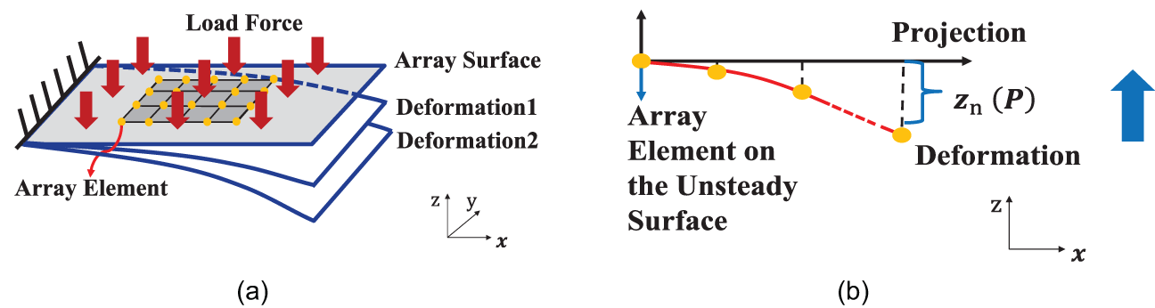
Figure 1. Design model of the pattern synthesis of phased array with unsteady surface deformation. (a) The schematic diagram of the antenna surface deformation. (b) The schematic diagram at x-z plane.
where  $N$ is the total element number,
  $E$ is the elastic modulus,
  $EI$ is the bending stiffness based on the structure size and
  $E$,
$E$,  $l$ is the length of the cantilever plate, and P represents any form of external load, here it is the intensity of the uniform surface load.
Optimization formulation and sensitivity analysis
For the theoretical synthesis considering the above bending deformation of a cantilever plate, the following assumptions are made: (1) The configuration (e.g., length and width) of each element remains unchanged during the bending deformation. (2) The change in the mutual coupling among elements caused by the bending deformation is ignored. Then the possible deformed arrays can be simply reconstructed according to the varying centroid  $\left( {{x_n},{y_n},{z_n}\left( P \right)} \right)$ of each array element. The far-field pattern of array antenna is derived according to the superposition principle of phased array antenna [Reference Mailloux8], which is expressed as:
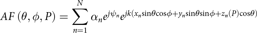 \begin{equation}AF\left( {\theta ,\phi ,P} \right) = \mathop \sum \limits_{n = 1}^{N} {\alpha _n}{e^{j{\psi _n}}}{e^{jk\left( {{x_n}{\textrm{sin}}\theta {\textrm{cos}}\phi + {y_n}{\textrm{sin}}\theta {\textrm{sin}}\phi + {z_n}\left( P \right){\textrm{cos}}\theta } \right)}}\end{equation}
 where  ${\alpha _n}$ is the amplitude of
  $n$th array element,
  ${\psi _n}$ is the phase of
  $n$th array element,
  $k$ is the wave number, and
  $\left( {\theta ,\phi } \right)$ is the polar variables.
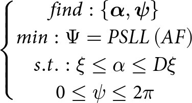
The synthesis problem is defined as follows: optimizing the excitation coefficients of each element simultaneously to suppress the peak sidelobe level (PSLL) when the array surface deforms with the varying loads. The optimization formulation is given as:
 \begin{equation}
\left\{ \begin{matrix}
{find: \left\{ {\bf{\alpha}, {\bf{\psi}}} \right\} } \\
{min: \Psi = PSLL\left( {AF} \right)} \\
{s.t.: \xi \le \alpha \le D\xi } \\
{ 0 \le \psi \le 2\pi } \\
\end{matrix} \right.
\end{equation}
\begin{equation}
\left\{ \begin{matrix}
{find: \left\{ {\bf{\alpha}, {\bf{\psi}}} \right\} } \\
{min: \Psi = PSLL\left( {AF} \right)} \\
{s.t.: \xi \le \alpha \le D\xi } \\
{ 0 \le \psi \le 2\pi } \\
\end{matrix} \right.
\end{equation} where PSLL is the peak sidelobe level,  $\xi \le \bf{\alpha} \le D\xi $ denote the DRR constrains,
  $\xi $ is an auxiliary variable, and
  $D$ is the upper threshold of DRR. In order to solve the optimization problem efficiently with the gradient-based algorithm, the objective PSLL(AF) should be defined as a continuous function, and its gradient with respect to the design variables
  $\left\{ {\bf{\alpha}, {\bf{\psi}}} \right\}$ should be calculated analytically. For the sidelobe suppression problem, the Kreisselmeier–Steinhauser function is utilized to smooth the objective function [Reference Wang, Zheng, Yu, Gao and Liu19], and according to the chain rule, the sensitivities are expressed as:
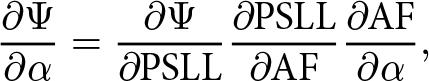 \begin{equation}{{\partial {{\Psi }}} \over {\partial \alpha }} = {{\partial {{\Psi }}} \over {\partial {\textrm{PSLL}}}}{{\partial {\textrm{PSLL}}} \over {\partial {\textrm{AF}}}}{{\partial {\textrm{AF}}} \over {\partial \alpha }},\end{equation}
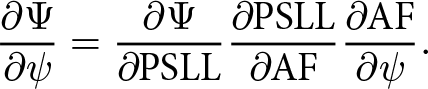 \begin{equation}{{\partial {{\Psi }}} \over {\partial \psi }} = {{\partial {{\Psi }}} \over {\partial {\textrm{PSLL}}}}{{\partial {\textrm{PSLL}}} \over {\partial {\textrm{AF}}}}{{\partial {\textrm{AF}}} \over {\partial \psi }}.\end{equation}
When the position of array elements changes, the pattern can also be synthesized by compensating the wave path difference [Reference Kobayashi17]. For the mechanical deformation in equation (1), the array factor with compensation is given by:
 \begin{equation}E\left( {\theta ,\phi ,P} \right) = \mathop \sum \limits_{n = 1}^{N} {\alpha _n}{e^{ - jkD{D_n}}}{e^{jk\left( {{x_n}{\textrm{sin}}\theta {\textrm{cos}}\phi + {y_n}{\textrm{sin}}\theta {\textrm{sin}}\phi + {z_n}\left( P \right){\textrm{cos}}\theta } \right)}}\end{equation}
 \begin{equation}D{D_n}\left( P \right) = {x_n}\sin {\theta _0}\cos {\phi _0} + {y_n}\sin {\theta _0}\sin {\phi _0} + {z_n}\left( P \right)\cos {\theta _0},\end{equation}
 where  $D{D_n}\left( P \right)$ denotes the path-length, (
 ${\theta _0},{\phi _0}$) is the beam direction. The optimized excitations can be treated as a better initial solution, and phase excitation coefficients can be derived according to equation (6) for different deformation. It is worth mentioning that we can directly use the optimized amplitude and phase excitations for the compensation, or we can choose to use the amplitude excitation as the initial solution and then use equation (6) to derive the phase excitation under different deformations.
Procedure of the proposed method
The general procedure of the proposed method is given as follows:
(1) Preparation for the mechanical deformation analysis where the array surface size, initial element locations, the bending stiffness
 $EI$, and the loads P are set.
(2) Calculating the mechanical deformation form as equation (1), and reconstructing the deformed array and modifying the array factor in equation (2). It is worth mentioning that, when the value of P changes, the deformation form (the relationship among the changed locations of different elements) remains, and the deformation value (changed locations) is associated with P.
(3) Preparation for the pattern synthesis, where
${\bf{\alpha}_{ini}}$ and $ {{\bf{\psi}}_{ini}}$ are set.(4) For a given P, calculating the radiation properties to obtain the design objective in equation (3).
(5) Calculating the sensitivities of the design objective with respect to
$\bf{\alpha}$ and ${\bf{\psi}}$ as equations (4) and (5).(6) Updating
$\bf{\alpha}$ and ${\bf{\psi}}$ by the use of a gradient-based algorithm. If $\bf{\alpha}$ and ${\bf{\psi}}$ have converged, the synthesis stops; if not, the synthesis goes to (4).(7) For different P, repeat (4)–(6) to obtain different solutions or use one of these solutions (i.e., optimized amplitude solution) and the phase compensation excitation as equation (6) to realize the compensation for different P (within a feasible range of P value).


Numerical results
In this selection, we provide several examples to evaluate the effectiveness of the proposed method. The synthesis problem is optimized by the sequential quadratic programming algorithm. The optimization is computed using a 2.90 GHz i7-10700 K CPU and 32 GB RAM.
Case 1
We consider a linear array that has 30 elements with inter-element spacing  $d = 0.5\lambda $, where
  $\lambda $ is the wavelength of the simulation frequency. The material of the cantilever plate is aluminum 6061 with elastic modulus
  $E$ of 68.9 GPa, and the length of the cantilever plate is 30
 $\lambda $. The array surface is bent and deformed by a uniform load. The design objective is to suppress the PSLL while steering the main beam at
  $ {\theta _0} = 0^\circ $ and
  ${\phi _0} = 0^\circ $ with a main beam width
  $\left| \theta \right| \le 5^\circ $.
First, the radiation performance without deformation (i.e.,  ${z_{{\textrm{max}}}}\left( P \right) = 0$, where
  ${z_{{\textrm{max}}}}\left( P \right)$ denotes the maximum deformation of array elements under
  $P$ load) under different DRR is studied. The DRR threshold is set to be 2, 3, and 4. The calculation time for the optimization design is about 10 s. Figure 2 shows the normalized pattern and the amplitude distribution of each element with different DRR. It is seen that the PSLL increases from −27.93 dB to −24.59 dB as the DRR decreases from 4 to 2, which illustrates that the DRR constraint is activated during the optimization and the DRR value affects the radiation performance.
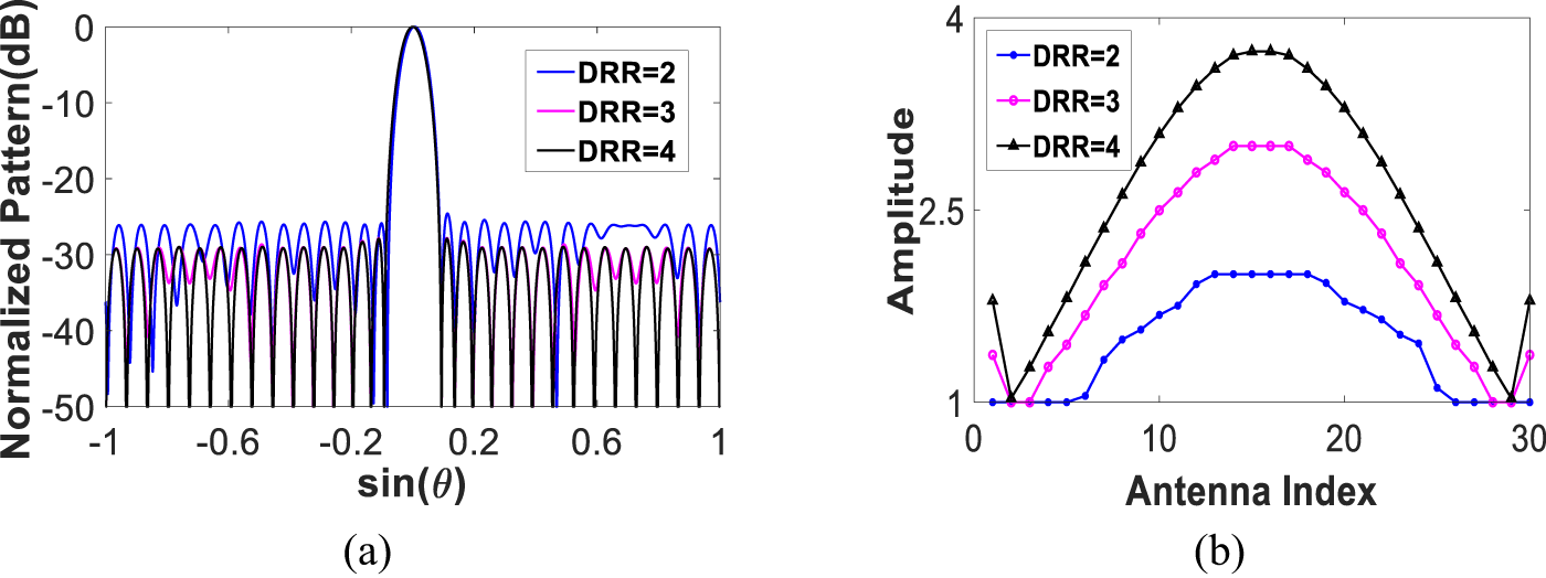
Figure 2. Results of the array antenna without deformation under different DRR: (a) normalized pattern and (b) amplitude excitation.
Case 2
In the second case, we use the amplitude obtained from the Chebyshev [Reference Mailloux8] with and without the phase compensation in equation (6) as a comparison. Herein, the excitation coefficient obtained by Chebyshev with a sidelobe level equal to −30 dB is applied to the deformed array.  ${z_{{\textrm{max}}}}\left( P \right)$ is taken as
  $0.5\lambda $,
  $\lambda $, and
  $1.5\lambda $, respectively. The normalized pattern with
  ${z_{{\textrm{max}}}}\left( P \right) = \lambda $ is given in Fig. 3, the excitation coefficient is given in Fig. 4, and the radiation properties are listed in Table 1.
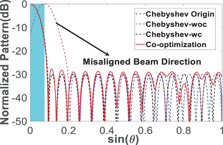
Figure 3. Performance comparison with  ${z_{{\textrm{max}}}}\left( P \right) = \lambda $.
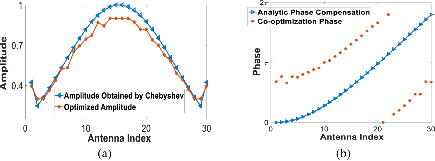
Figure 4. Excitation coefficient after optimization with  ${z_{{\textrm{max}}}}\left( P \right) = \lambda $: (a) amplitude excitation and (b) phase excitation.
Table 1. Radiation properties of the synthesis
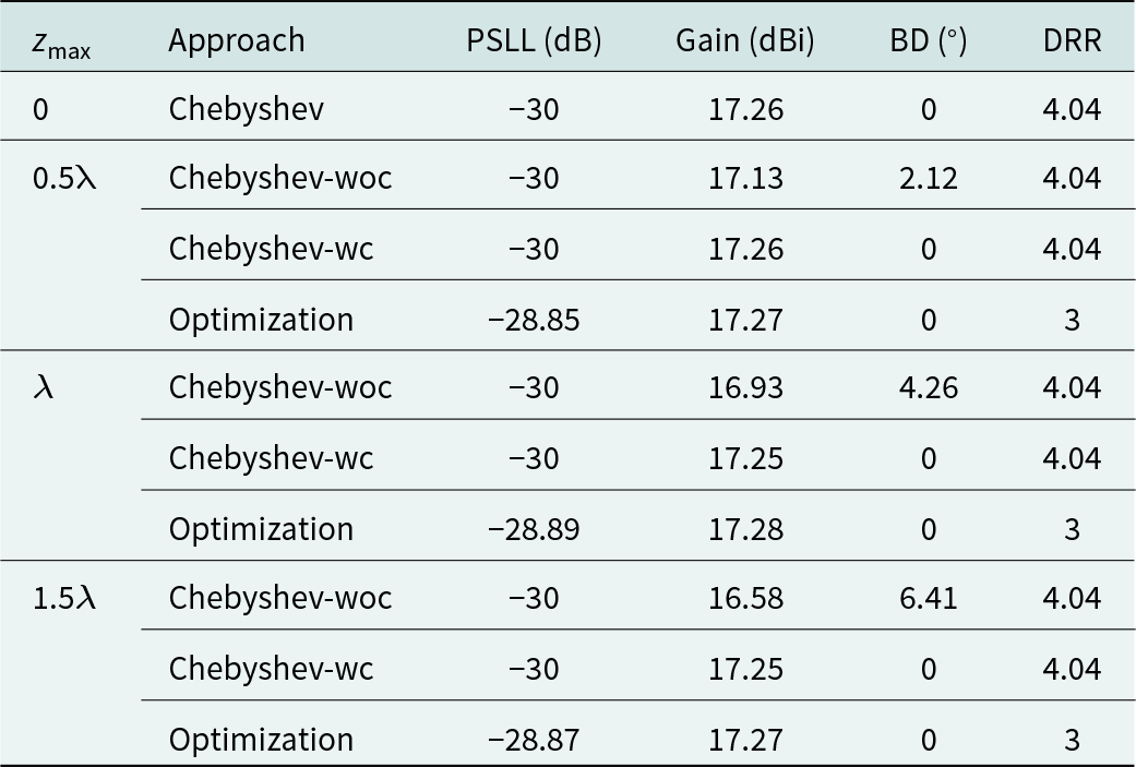
When the surface deforms with different  ${z_{{\textrm{max}}}}\left( P \right)$, the main beam deviation of the array with the excitation coefficient obtained by Chebyshev without any compensation (Chebyshev-woc) increases gradually as
  ${z_{{\textrm{max}}}}\left( P \right)$ increases (from
  $2.12^\circ $ to
  $6.41^\circ $). After the optimization, the PSLLs are suppressed successfully and the main beam is adjusted to the desired direction. The PSLL is optimized to −28.85 dB, −28.89 dB, and −28.87 dB, respectively. The optimized normalized pattern closes to the pattern obtained by Chebyshev with phase compensation (Chebyshev-wc) and the DRR is optimized to 3, which decreases by 1.04 compared with the Chebyshev results.
Case 3
In this case, the linear array in the first example is deformed by a concentrated load, and all parameters of cantilever plate remain unchanged. The bending deformation satisfies:
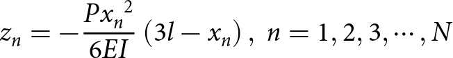 \begin{equation}{z_n} = - {{P{x_n}^2} \over {6EI}}\left( {3l - {x_n}} \right),{\ }n = 1,2,3, \cdots ,N\end{equation}
 where  $P$ is the concentrated load on the free end of the plate.
  ${z_{{\textrm{max}}}}$ takes
  $\lambda $, and the DRR threshold is set to be 3. The calculation time for the optimization design is about 10 s. The PSLL is suppressed to −28.87 dB, and the gain is optimized to 17.26 dB, which is close to the pattern obtained by Chebyshev without any deformation with lower DRR. The patterns and excitation coefficient are given in Fig. 5.
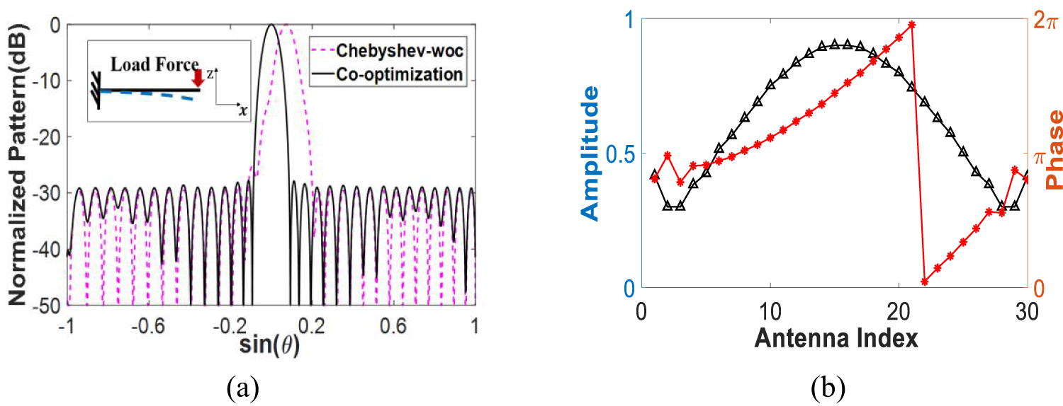
Figure 5. Pattern and excitations: (a) normalized pattern and (b) excitations.
Then, we consider another deformation type where the array surface is equivalently transformed into a plate fixed at both ends and is deformed by a concentrated load. All parameters of plate remain unchanged, and the bending deformation satisfies:
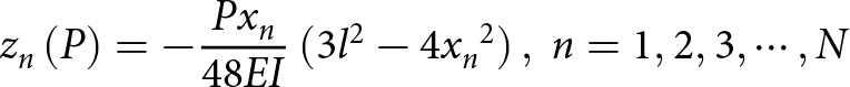 \begin{equation}{z_n}\left( P \right) = - {{P{x_n}} \over {48EI}}\left( {3{l^2} - 4{x_n}^2} \right),{\ }n = 1,2,3, \cdots ,N\end{equation}
 where  $P$ is the concentrated load and
  ${z_{{\textrm{max}}}}\left( P \right)$ takes
  $\lambda $. The PSLL is suppressed to −28.85 dB, which decreases by about 6.13 dB compared with the pattern obtained by Chebyshev-woc (DRR = 4.04) with lower DRR (DRR = 3). The patterns and excitation coefficients are given in Fig. 6. The results show that different types of array deformations cause different forms of distortion in the array pattern, and the proposed approach can recover the radiation pattern from a deteriorate pattern caused by the unsteady deformations.
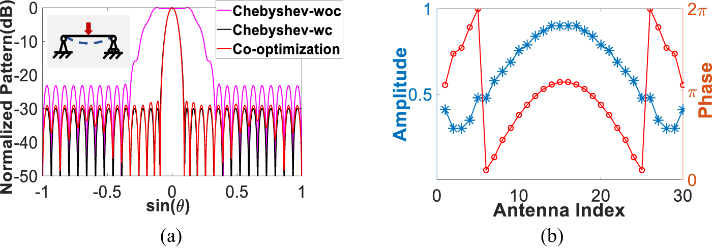
Figure 6. Pattern and excitations: (a) normalized pattern and (b) excitations.
Case 4
Finally, we study the regularity of the excitation coefficients. In this case, we use the linear array in the first example, and the deformation form of the array follows (1). The radiation performance for the deformation of  ${z_{{\textrm{max}}}}\left( P \right) = 0.1\lambda $ to
  $0.9\lambda $, with an interval of
  $0.1\lambda $, is calculated. We use the optimized amplitude and the derived phase excitations obtained by equation (6). Figure 7 shows the optimized amplitude and phase excitation coefficients (obtained by equation (6)) of each element, and Fig. 8 shows the normalized pattern (for each case, the optimal PSLLs are around −26.33 dB). It is worth mentioning that, when
  ${z_{{\textrm{max}}}}\left( P \right) = 0.5\lambda $, we compare the calculation results with those in the electromagnetic simulation software FEKO. The result is also plotted in Fig. 8, and it shows an agreement.
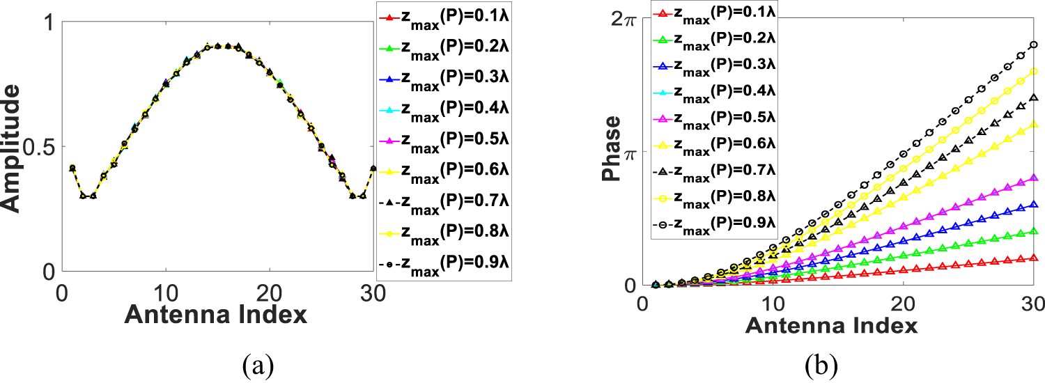
Figure 7. Excitations with different  ${z_{{\textrm{max}}}}\left( P \right)$: (a) amplitude excitation and (b) phase excitation.
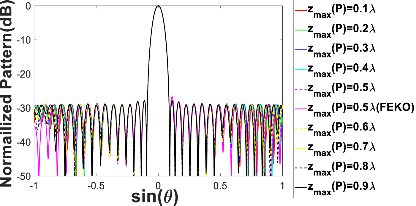
Figure 8. Normalized pattern with different  ${z_{{\textrm{max}}}}\left( P \right)$.
It is seen that as the deformation increases, the amplitude excitations obtained from the optimization do not change much. So, the set of optimized solutions (amplitude excitations) is treated as an initial solution, and phase excitation coefficients are obtained by equation (6) (the phase excitations are within one group [see Fig.7(b)]), which can effectively reduce the amount of equipment data stored. For practical applications, it provides a feasible way to reduce the complexity of beamforming network through determining a set of excitations.
Conclusion
This paper presents an optimization method for pattern synthesis of distorted phased array antenna with unsteady surface deformation considering DRR control. The main contribution is labeled as combining the pattern synthesis with the mechanical deformation analysis, where the possible deformed arrays are reconstructed according to the varying loads, and the distorted patterns are recovered with DRR control. In any future work, the approach needs to be improved from the following aspects:
(1) Considering more complex mechanical deformations, where the computational mechanics, such as the finite element method, could be used in the deformation analysis and arrangement reconstruction.
(2) Considering actual array antenna structures, where the changes in both the element configuration and the mutual coupling among elements should be involved in the synthesis.
Funding statement
This work was supported by the National Natural Science Foundation of China under project number 12172076 and the Fundamental Research Funds for the Central Universities of China under project number DUT22LAB122.
Competing interests
The authors report no conflict of interest.
Qi Wang received B.S. and Ph.D. degrees in engineering mechanics from Dalian University of Technology, Dalian, Liaoning, in 2010 and 2017, respectively. Since 2021, he has been an Associate Professor with the School of Automotive Engineering, Dalian University of Technology. His current research interests include design optimization in electromagnetics, topology optimization, antennas, arrays, sensors, and metamaterials.

Yuanxin Yu received the B.S. degree in vehicle engineering from Shenyang Ligong University, Shenyang, China, in 2020. She is currently pursuing the M.S. degree with the School of Automotive Engineering, Dalian University of Technology, Dalian, China. Her current research interests include optimization in electromagnetic and array antenna optimization.

Yuning Pan received B.S. degree in vehicle engineering from Northeastern University, Shenyang, China, in 2020. Now he is pursuing the M.S. degree with the School of Automotive Engineering, Dalian University of Technology, Dalian, China. Her current research interests include array antenna optimization and hardware implementation.
Renjing Gao received M.S. and Ph.D. degrees in electronic engineering from Dalian University of Technology, Dalian, China, in 2002 and 2012, respectively. Since 1994, she has been with the Dalian University of Technology, where she is currently a professor with the School of Automotive Engineering. She has performed research and published over 60 papers in a wide variety of design topics, including left-handed materials, mass sensors, digital control systems, and microelectromechanical systems. She holds 20+ Chinese Patents.

Shutian Liu received B.S. and Ph.D. degrees in engineering mechanics from Dalian University of Technology, Dalian, Liaoning, in 1982 and 1994, respectively. Now he works as a professor in the State Key Laboratory of Structural Analysis for Industrial Equipment, Dalian University of Technology. He performed and published more than 200 papers and holds 20+ Chinese Patens. His major research fields include structural and multidisciplinary optimization, computational mechanics, and metamaterial design.


