1 Introduction
The output power of single chain fiber laser has been growing in recent years due to the fast development of pump laser diode (LD), active fiber, advanced heat management method, and so on. There has been a long time when stimulated Raman scattering (SRS) effect is considered to be one of the main obstacles for power scaling in general-type fiber lasers[Reference Zervas and Codemard1–Reference Zhu, Zhou, Ma, Xu and Liu3]. The generation of SRS in fiber laser system might cause serious effects due to the backscattered Stokes light[Reference Rosales-Garcia, Tobioka, Abedin, Dong, Várallyay, Szabó, Taunay, Sullivan and Headley4]. Therefore, SRS in high-power fiber laser system has been under intensive investigation and lots of technical solutions to suppress SRS have been proposed and validated, such as employing large-mode-area fiber, and decreasing the length of active fiber by using highly doped fiber[Reference Rosales-Garcia, Tobioka, Abedin, Dong, Várallyay, Szabó, Taunay, Sullivan and Headley4–Reference Dianov, Likhachev and Fevrier10]. Nevertheless, these are not intrinsic solutions and sometimes they would bring in side effects. For example, increasing the mode area would degrade the beam quality apart from mode control techniques. Using highly doped gain fiber may increase the thermal load per length and enhance the photon-darkening effect. However, from the other point of view, SRS can be used to help lasing, which is often called Raman fiber laser. Raman fiber laser has unique properties such as the broad gain spectrum and the wavelength versatility, which have been demonstrated in a large variety of wavelength bands[Reference Feng, Taylor and Bonaccini Calia11–Reference Vincent, Martin, Julien and Vallée21].
Up to now, most of the reported Raman fiber laser is achieved by core-pumping single-mode (SM) fiber, where the output power is determined directly by the pump laser. The maximal output power of the conventional core-pumped Raman fiber laser is about several-hundred-watt level[Reference Feng, Taylor and Calia13–Reference Supradeepa and Nicholson16]. In addition, the brightness can not be increased in the core-pumping configuration. Cladding pumped Raman fiber laser by using double-clad (DC) fiber has the potential for power scaling because of the significant increase in pump power[Reference Bernier, Fortin, Caron, El-Amraoui, Messaddeq and Vallée22–Reference Codemard, Ji, Sahu and Nilsson26]. In order to increase the conversion efficiency, specialized fiber is often required in cladding pumped fiber lasers, by which hundred-watt level output power has been achieved[Reference Codemard, Dupriez, Jeong, Sahu, Ibsen and Nilsson24]. It is to be noted that recently LD pumped Raman fiber laser based on multimode (MM) fiber has also drawn intensive attention[Reference Kablukov, Dontsova, Zlobina, Nemov, Vlasov and Babin27–Reference Glick, Fromzel, Zhang, Ter-Gabrielyan and Dubinsii30] because of its potential in brightness enhancement due to the self-beam cleanup effect in MM fiber[Reference Terry, Engel, Alley and Russell31, Reference Baek and Roh32]. Up to 140 watts level output power has been reported[Reference Glick, Fromzel, Zhang, Ter-Gabrielyan and Dubinsii30]. Generally, by now, pure Raman fiber lasers based on various kinds of configurations, including core-pumping SM fiber, cladding pumping DC fiber, and LD pumped MM fiber, have been successfully demonstrated. Nevertheless, the maximal output power is hundreds of watts, which is much lower than that of fiber lasers based on active fiber.
Recently, several independent groups have proposed a novel system setup[Reference Zhang, Jiang, Cui and Feng33–Reference Liu, Tan, Shi and Wang40] named Yb-Raman fiber amplifier or nonlinear fiber amplifier (NFA, we call it nonlinear fiber amplifier in this paper), where laser gain provided by both SRS and active fiber is employed. In this new setup, the signal laser is firstly amplified via doped ions in the fiber and then the laser power is transferred into Stokes wave via SRS effect. Cladding pumping technique is employed in the system to ensure sufficient pumping power. Raman gain is employed designedly to induct forward scattered Stokes light and reduce the unwanted backscattered Stokes light. In addition, the system setup is compatible with standard fiber laser configuration that is usually based on master oscillator power amplifier (MOPA). Thus COTS active fiber and fiber components can be used without special design. Based on the aforementioned properties, NFA has achieved significant results in recent 5 years and has become a new route for high-power fiber lasers. Near 4 kW level output power based on Yb gain and Raman gain has been realized[Reference Xiao, Yan, Li, Sun, Wang, Huang and Gong37], which is comparable with standard fiber laser/amplifier. And this concept has been extended to obtain high-power lasing at
![]() $2~\unicode[STIX]{x03BC}\text{m}$
band based on both Tm gain and Raman gain[Reference Liu, Tan, Shi and Wang40].
$2~\unicode[STIX]{x03BC}\text{m}$
band based on both Tm gain and Raman gain[Reference Liu, Tan, Shi and Wang40].
In the present paper, we provide a general and detailed study on high-power NFA. In Section 2, we present the physical modeling of the NFA. Based on the physical model, numerical programs are developed. The power scaling potential, effect of backscattered Stokes light suppression, and heat analysis of the NFA will be studied for the first time in Section 3. In Section 4, experimental results of NFA, including LD pumped NFA and tandem-pumped NFA will be demonstrated, where tandem-pumped NFA is presented for the first time. In Section 5, further investigation on several new issues, including the four wave mixing (FWM), the mode instability (MI) and photon darkening (PD) in the system will be presented. The conclusion and discussion on future endeavors will be drawn in Section 6.
2 Modeling of nonlinear fiber amplifier
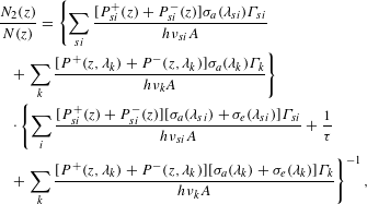
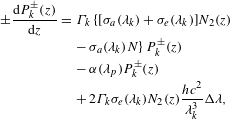
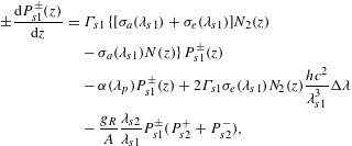
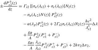
The general system setup of an NFA is plotted in Figure 1. Without loss of conventionality, we focus on NFA based on Yb-doped fiber in this paper. The NFA is similar to conventional Yb-doped fiber amplifier (YDFA) in system structure. The main difference is in the seed. It is a two- or multi-wavelength seed. The shortest wavelength usually locates at the gain peak of the Yb-doped fiber (YDF) and the other wavelengths correspond to each order of Raman Stokes waves. For example, if Seed 1 is 1070 nm laser, the wavelength of Seed 2 can be 1120 nm in silica fiber. It is to be noted that Seed 2 can also be provided by the spontaneous noise generated inside Seed 1[Reference Xiao, Yan, Li, Sun, Wang, Huang and Gong37]. Since the gain obtained from Yb-ion and Raman scattering is based on different mechanisms, the phase-coupling between Yb gain and Raman gain can be neglected. In this case, the coupling between Yb gain and Raman gain can be achieved by intensity items. Such amplifiers can be numerically studied by a set of rate equations including both Yb and Raman amplifications[Reference Zhang, Xiao, Zhou, Wang and Xu34].
 $$\begin{eqnarray}\displaystyle & & \displaystyle \frac{N_{2}(z)}{N(z)}=\left\{\mathop{\sum }_{si}\frac{[P_{si}^{+}(z)+P_{si}^{-}(z)]\unicode[STIX]{x1D70E}_{a}(\unicode[STIX]{x1D706}_{si})\unicode[STIX]{x1D6E4}_{si}}{h\unicode[STIX]{x1D708}_{si}A}\right.\nonumber\\ \displaystyle & & \displaystyle \quad +\left.\mathop{\sum }_{k}\frac{[P^{+}(z,\unicode[STIX]{x1D706}_{k})+P^{-}(z,\unicode[STIX]{x1D706}_{k})]\unicode[STIX]{x1D70E}_{a}(\unicode[STIX]{x1D706}_{k})\unicode[STIX]{x1D6E4}_{k}}{h\unicode[STIX]{x1D708}_{k}A}\right\}\nonumber\\ \displaystyle & & \displaystyle \quad \cdot \left\{\mathop{\sum }_{i}\frac{[P_{si}^{+}(z)+P_{si}^{-}(z)][\unicode[STIX]{x1D70E}_{a}(\unicode[STIX]{x1D706}_{si})+\unicode[STIX]{x1D70E}_{e}(\unicode[STIX]{x1D706}_{si})]\unicode[STIX]{x1D6E4}_{si}}{h\unicode[STIX]{x1D708}_{si}A}+\frac{1}{\unicode[STIX]{x1D70F}}\right.\nonumber\\ \displaystyle & & \displaystyle \quad +\left.\mathop{\sum }_{k}\frac{[P^{+}(z,\unicode[STIX]{x1D706}_{k})+P^{-}(z,\unicode[STIX]{x1D706}_{k})][\unicode[STIX]{x1D70E}_{a}(\unicode[STIX]{x1D706}_{k})+\unicode[STIX]{x1D70E}_{e}(\unicode[STIX]{x1D706}_{k})]\unicode[STIX]{x1D6E4}_{k}}{h\unicode[STIX]{x1D708}_{k}A}\right\}^{-1},\nonumber\\ \displaystyle & & \displaystyle\end{eqnarray}$$
 $$\begin{eqnarray}\displaystyle \pm \frac{\text{d}P_{k}^{\pm }(z)}{\text{d}z} & = & \displaystyle \unicode[STIX]{x1D6E4}_{k}\{[\unicode[STIX]{x1D70E}_{a}(\unicode[STIX]{x1D706}_{k})+\unicode[STIX]{x1D70E}_{e}(\unicode[STIX]{x1D706}_{k})]N_{2}(z)\nonumber\\ \displaystyle & & \displaystyle -\,\unicode[STIX]{x1D70E}_{a}(\unicode[STIX]{x1D706}_{k})N\!\}P_{k}^{\pm }(z)\nonumber\\ \displaystyle & & \displaystyle -\,\unicode[STIX]{x1D6FC}(\unicode[STIX]{x1D706}_{p})P_{k}^{\pm }(z)\nonumber\\ \displaystyle & & \displaystyle +\,2\unicode[STIX]{x1D6E4}_{k}\unicode[STIX]{x1D70E}_{e}(\unicode[STIX]{x1D706}_{k})N_{2}(z)\frac{hc^{2}}{\unicode[STIX]{x1D706}_{k}^{3}}\unicode[STIX]{x0394}\unicode[STIX]{x1D706},\end{eqnarray}$$
 $$\begin{eqnarray}\displaystyle \pm \frac{\text{d}P_{s1}^{\pm }(z)}{\text{d}z} & = & \displaystyle \unicode[STIX]{x1D6E4}_{s1}\{[\unicode[STIX]{x1D70E}_{a}(\unicode[STIX]{x1D706}_{s1})+\unicode[STIX]{x1D70E}_{e}(\unicode[STIX]{x1D706}_{s1})]N_{2}(z)\nonumber\\ \displaystyle & & \displaystyle -\,\unicode[STIX]{x1D70E}_{a}(\unicode[STIX]{x1D706}_{s1})N(z)\!\}P_{s1}^{\pm }(z)\nonumber\\ \displaystyle & & \displaystyle -\,\unicode[STIX]{x1D6FC}(\unicode[STIX]{x1D706}_{p})P_{s1}^{\pm }(z)+2\unicode[STIX]{x1D6E4}_{s1}\unicode[STIX]{x1D70E}_{e}(\unicode[STIX]{x1D706}_{s1})N_{2}(z)\frac{hc^{2}}{\unicode[STIX]{x1D706}_{s1}^{3}}\unicode[STIX]{x0394}\unicode[STIX]{x1D706}\nonumber\\ \displaystyle & & \displaystyle -\,\frac{g_{R}}{A}\frac{\unicode[STIX]{x1D706}_{s2}}{\unicode[STIX]{x1D706}_{s1}}P_{s1}^{\pm }(P_{s2}^{+}+P_{s2}^{-}),\end{eqnarray}$$
 $$\begin{eqnarray}\displaystyle \pm \frac{\text{d}P_{s2}^{\pm }(z)}{\text{d}z} & = & \displaystyle \unicode[STIX]{x1D6E4}_{s2}\{[\unicode[STIX]{x1D70E}_{a}(\unicode[STIX]{x1D706}_{s2})+\unicode[STIX]{x1D70E}_{e}(\unicode[STIX]{x1D706}_{s2})]N_{2}(z)\nonumber\\ \displaystyle & & \displaystyle -\,\unicode[STIX]{x1D70E}_{a}(\unicode[STIX]{x1D706}_{s2})N(z)\!\}P_{s2}^{\pm }(z)\nonumber\\ \displaystyle & & \displaystyle -\,\unicode[STIX]{x1D6FC}(\unicode[STIX]{x1D706}_{p})P_{s2}^{\pm }(z)+2\unicode[STIX]{x1D6E4}_{s2}\unicode[STIX]{x1D70E}_{e}(\unicode[STIX]{x1D706}_{s2})N_{2}(z)\frac{hc^{2}}{\unicode[STIX]{x1D706}_{s2}^{3}}\unicode[STIX]{x0394}\unicode[STIX]{x1D706}\nonumber\\ \displaystyle & & \displaystyle +\,\frac{g_{R}}{A}P_{s2}^{\pm }(P_{s1}^{+}+P_{s1}^{-})\nonumber\\ \displaystyle & & \displaystyle -\,\frac{g_{R1}}{A}\frac{\unicode[STIX]{x1D706}_{s3}}{\unicode[STIX]{x1D706}_{s2}}P_{s2}^{\pm }(P_{s3}^{+}+P_{s3}^{-})+2hv_{2}\unicode[STIX]{x0394}v_{2},\end{eqnarray}$$
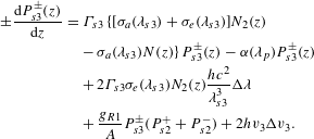 $$\begin{eqnarray}\displaystyle \pm \frac{\text{d}P_{s3}^{\pm }(z)}{\text{d}z} & = & \displaystyle \unicode[STIX]{x1D6E4}_{s3}\{[\unicode[STIX]{x1D70E}_{a}(\unicode[STIX]{x1D706}_{s3})+\unicode[STIX]{x1D70E}_{e}(\unicode[STIX]{x1D706}_{s3})]N_{2}(z)\nonumber\\ \displaystyle & & \displaystyle -\,\unicode[STIX]{x1D70E}_{a}(\unicode[STIX]{x1D706}_{s3})N(z)\!\}P_{s3}^{\pm }(z)-\unicode[STIX]{x1D6FC}(\unicode[STIX]{x1D706}_{p})P_{s3}^{\pm }(z)\nonumber\\ \displaystyle & & \displaystyle +\,2\unicode[STIX]{x1D6E4}_{s3}\unicode[STIX]{x1D70E}_{e}(\unicode[STIX]{x1D706}_{s3})N_{2}(z)\frac{hc^{2}}{\unicode[STIX]{x1D706}_{s3}^{3}}\unicode[STIX]{x0394}\unicode[STIX]{x1D706}\nonumber\\ \displaystyle & & \displaystyle +\,\frac{g_{R1}}{A}P_{s3}^{\pm }(P_{s2}^{+}+P_{s2}^{-})+2hv_{3}\unicode[STIX]{x0394}v_{3}.\end{eqnarray}$$
The emission spectrum of Yb-doped fiber (from 970 nm to 1200 nm) can be divided into discrete spectral channels with width of
![]() $\unicode[STIX]{x0394}\unicode[STIX]{x1D706}$
. The subscript
$\unicode[STIX]{x0394}\unicode[STIX]{x1D706}$
. The subscript
![]() $k$
represents the
$k$
represents the
![]() $k$
th channel but
$k$
th channel but
![]() $p$
,
$p$
,
![]() $s_{1}$
and
$s_{1}$
and
![]() $s_{2}$
represent the pump and two signal waves specially. The superscript
$s_{2}$
represent the pump and two signal waves specially. The superscript
![]() $\pm$
corresponds to positive and negative directions, respectively.
$\pm$
corresponds to positive and negative directions, respectively.
![]() $N(z)$
is the Yb ions concentration distribution along the fiber, for passive fiber
$N(z)$
is the Yb ions concentration distribution along the fiber, for passive fiber
![]() $N(z)=0$
;
$N(z)=0$
;
![]() $N_{2}(z)$
is the excited state population;
$N_{2}(z)$
is the excited state population;
![]() $P_{si}$
represents the signal power;
$P_{si}$
represents the signal power;
![]() $P(z,\unicode[STIX]{x1D706}_{k})$
is the power of laser
$P(z,\unicode[STIX]{x1D706}_{k})$
is the power of laser
![]() $\unicode[STIX]{x1D706}_{k}$
;
$\unicode[STIX]{x1D706}_{k}$
;
![]() $\unicode[STIX]{x1D70E}_{a}$
and
$\unicode[STIX]{x1D70E}_{a}$
and
![]() $\unicode[STIX]{x1D70E}_{e}$
are Yb absorption and emission cross sections, respectively[Reference Paschotta, Nilsson, Tropper and Hanna41].
$\unicode[STIX]{x1D70E}_{e}$
are Yb absorption and emission cross sections, respectively[Reference Paschotta, Nilsson, Tropper and Hanna41].
![]() $\unicode[STIX]{x1D6E4}$
is the overlapping factor between the pump (ASE signal) and the fiber doped area.
$\unicode[STIX]{x1D6E4}$
is the overlapping factor between the pump (ASE signal) and the fiber doped area.
![]() $g_{R}$
is the Raman gain coefficient;
$g_{R}$
is the Raman gain coefficient;
![]() $\unicode[STIX]{x1D6FC}$
is the loss coefficient.
$\unicode[STIX]{x1D6FC}$
is the loss coefficient.
![]() $2hv\unicode[STIX]{x0394}v$
is the Raman noise and the factor 2 corresponds to two polarization states.
$2hv\unicode[STIX]{x0394}v$
is the Raman noise and the factor 2 corresponds to two polarization states.
![]() $h$
is the Planck constant;
$h$
is the Planck constant;
![]() $v$
is frequency;
$v$
is frequency;
![]() $\unicode[STIX]{x0394}v$
is bandwidth of the signal. For spontaneous Raman noise we assume the bandwidth equals the gain bandwidth that is about40 THz.
$\unicode[STIX]{x0394}v$
is bandwidth of the signal. For spontaneous Raman noise we assume the bandwidth equals the gain bandwidth that is about40 THz.

Figure 1. The basic system setup of the NFA.
The boundary conditions can be described by the following equations:
where
![]() $R_{1}$
and
$R_{1}$
and
![]() $R_{2}$
refer to the reflectivity in the left and right side, respectively. Then this model can be numerically calculated by the finite-difference method[Reference Wang and Po42].
$R_{2}$
refer to the reflectivity in the left and right side, respectively. Then this model can be numerically calculated by the finite-difference method[Reference Wang and Po42].
3 Numerical analysis of nonlinear fiber amplifier
3.1 Power scaling potential of NFA
SRS is a main restriction for the power scaling of wide bandwidth YDFA. There is still not a straightforward technique that can suppress SRS effectively without introducing any drawback in YDFA. In this section we would like to show the advantage of the NFA in the potential of suppressing SRS by using a numerical example. The parameters used in the calculation are shown in Table 1. It is a co-pumping scheme with power of 8000 W. The gain fiber is
![]() $20/400~\unicode[STIX]{x03BC}\text{m}$
(core/inner diameter) double cladding YDF.
$20/400~\unicode[STIX]{x03BC}\text{m}$
(core/inner diameter) double cladding YDF.
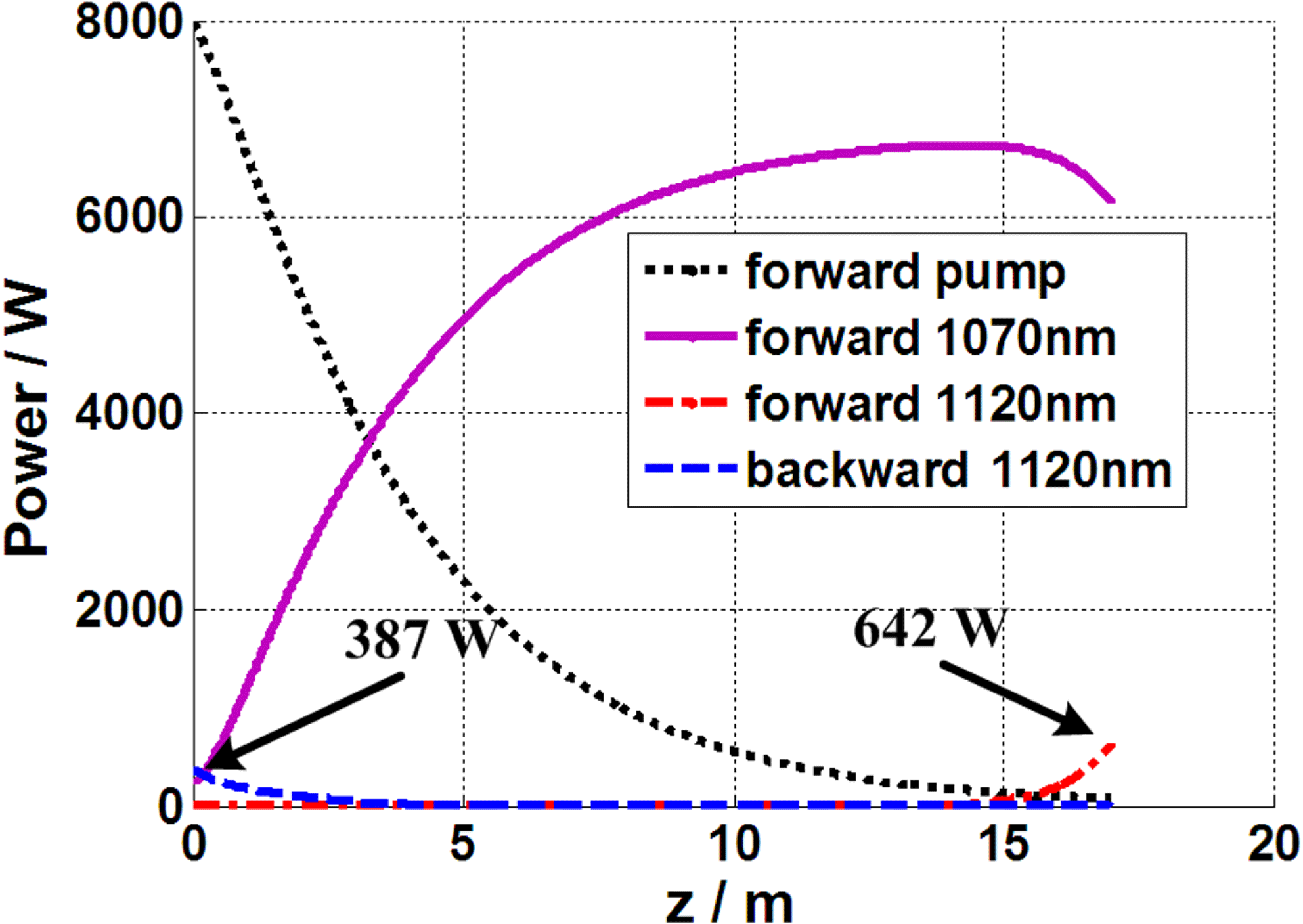
Figure 2. The power distribution of pump, signal, and Raman waves in forward and backward propagating directions. It can be found that Raman Stokes wave (1120 nm) has arisen in both directions, and the power is 642 W and 387 W for forward and backward directions, respectively.
Table 1. The parameters of the calculated fiber amplifier.
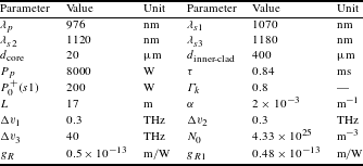
Firstly, we calculate a traditional case of only the 1070 nm laser in the seed. The seed power is 200 W. The power distribution along the fiber is shown in Figure 2. It can be found in this case that the signal power can reach more than 6000 W if other nonlinear effects or thermal effects are ignored. However, such a system is unpractical for Raman Stokes wave (1120 nm) that can be found in both directions. Especially in the backward direction, the power of 1120 nm laser in the fiber core is about 387 W, which is a big hidden danger for the high-power laser system. From this point of view, SRS is a limitation of the traditional Yb-doped fiber amplifier system. For comparison, we would like to give an example with similar condition for the NFA. The only change is that a 10 W 1120 nm laser is added in the seed. The 1120 nm laser corresponds to the first-order Stokes wave of 1070 nm laser. The other parameters of the amplifier are the same as that shown in Table 1.

Figure 3. (a) The power distribution of the pump, signal, and first-order Stokes waves; (b) the forward and (c) backward output spectra of the NFA. The seed is consisted of 200 W 1070 nm laser and 10 W 1120 nm laser, respectively.
Figure 3 is the calculated results of the NFA. In this amplifier, the 1070 nm laser is firstly amplified by the ytterbium gain, and as the 1120 nm laser propagates in the fiber core, it reaches the Raman threshold and begins to dominate the following amplification[Reference Zhang, Xiao, Zhou, Wang and Xu34]. Finally, the power of 1070 nm laser is all transferred to the Stokes wave (1120 nm) at the output end. It can be found in Figure 3(b) that the sum of the laser power of 1070 nm and 1180 nm is less than 5 W. At the backward output end, seen in Figure 3(c), the total output power in the fiber core is also small (less than 1 W). So in this NFA, the SRS would not limit the power amplification, indicating such an amplifier has higher SRS threshold than the case of conventional YDFA. It should be noted that in the calculation the bandwidth of the laser is ignored, but it has little influence on the calculation of Raman effect because of the wide bandwidth of Raman gain spectrum[Reference Agrawal43]. Accordingly, the spectral broadening of the 1070 nm laser in real experiment would not obviously reduce the gain of Raman Stokes wave for the conventional case of seed with 1–3 nm bandwidth.
3.2 Effect of suppressing backscattered Stokes light
From the numerical example mentioned in Section 3.1, we can also find that the NFA has the ability to suppress the back propagating light. With the help of the nonlinear interaction of the forward propagating 1070 nm and 1120 nm laser, the backward spontaneous Raman Stokes wave has been sufficiently suppressed. To quantificationally analyze the function of the Stokes wave in the seed on the generation of backward output laser, we calculated the backward output power of the amplifier proposed in Section 3.1 under conditions of different injected 1120 nm seed power. The result is shown in Figure 4. It is shown that there is a ‘perfect power’ for 1120 nm seed laser to make the backward output power minimal. In this case that the ‘perfect power’ is about 2 W, when the power of 1120 nm laser is smaller than this value, the seed is too weak to totally suppress the backward waves. However, high-power 1120 nm seed laser is not always good in decreasing the backward waves. As the 1120 nm laser power grows, the high-order Raman wave (1180 nm) starts to obtain gain due to the high-power seed induced Raman nonlinear interaction[Reference Wang, Yan, Xiong, Huang and Li44]. It can be understood by the inset of Figure 4. They are output spectra in backward direction. The high 1120 nm laser power case would result in more 1180 nm laser generation.

Figure 4. The dependence of backward output power on the power of 1120 nm seed laser. Insets are the output spectra in backward direction at different power.
Table 2. Parameters used to calculate the thermal distribution.

3.3 Heat analysis of NFA
Fiber laser has the advantage on thermal conduction due to its special geometry. But for high-power fiber laser system, fibers are not completely immune from thermal effects, so reducing the thermal burden is one of the most important things to guaranty the system running safety. Theoretically, the quantum defect of the nonlinear fiber amplifier is larger than that of conventional fiber amplifier because of the using of longer signal wavelength (e.g., 1120 nm compared with 1070 nm). In this section, we would compare the temperature distribution of these two kinds of amplifiers. The center temperature of the core
![]() $T_{0}$
in the YDF can be described by Equations (8) and (9)[Reference Fan, He, Zhou, Zheng, Liu, Wei, Dong and Lou45].
$T_{0}$
in the YDF can be described by Equations (8) and (9)[Reference Fan, He, Zhou, Zheng, Liu, Wei, Dong and Lou45].
 $$\begin{eqnarray}\displaystyle T_{0} & = & \displaystyle T_{c}+Q_{0}a^{2}\left[\frac{1}{2h_{_{\text{heat}}}c}+\frac{1}{4k_{1}}+\frac{1}{2k_{2}}\ln \left(\frac{b}{a}\right)\right.\nonumber\\ \displaystyle & & \displaystyle +\left.\frac{1}{2k_{3}}\ln \left(\frac{c}{a}\right)\right],\end{eqnarray}$$
 $$\begin{eqnarray}\displaystyle Q_{0}(z) & = & \displaystyle \left[\left|\frac{\text{d}P_{p}^{+}}{\text{d}z}\right|+\left|\frac{\text{d}P_{p}^{-}}{\text{d}z}\right|\right.\nonumber\\ \displaystyle & & \displaystyle -\left.\mathop{\sum }_{i}^{k,s_{1},s_{2},s_{3}}\left.\left(\left|\frac{\text{d}P_{i}^{+}}{\text{d}z}\right|+\left|\frac{\text{d}P_{i}^{-}}{\text{d}z}\right|\right)\right]\right/\unicode[STIX]{x1D70B}a^{2},\end{eqnarray}$$
where
![]() $k_{1}$
,
$k_{1}$
,
![]() $k_{2}$
, and
$k_{2}$
, and
![]() $k_{3}$
are the thermal conductivities in core, inner cladding, and outer cladding, respectively, and
$k_{3}$
are the thermal conductivities in core, inner cladding, and outer cladding, respectively, and
![]() $a$
,
$a$
,
![]() $b$
,
$b$
,
![]() $c$
are the diameter of the core, inner cladding, and outer cladding, respectively.
$c$
are the diameter of the core, inner cladding, and outer cladding, respectively.
![]() $T_{c}$
is the coolant temperature.
$T_{c}$
is the coolant temperature.
![]() $h_{\text{heat}}$
is the convective heat transfer coefficient.
$h_{\text{heat}}$
is the convective heat transfer coefficient.
![]() $Q_{0}(z)$
is the heat power density of the core, which can be calculated by Equation (9).
$Q_{0}(z)$
is the heat power density of the core, which can be calculated by Equation (9).
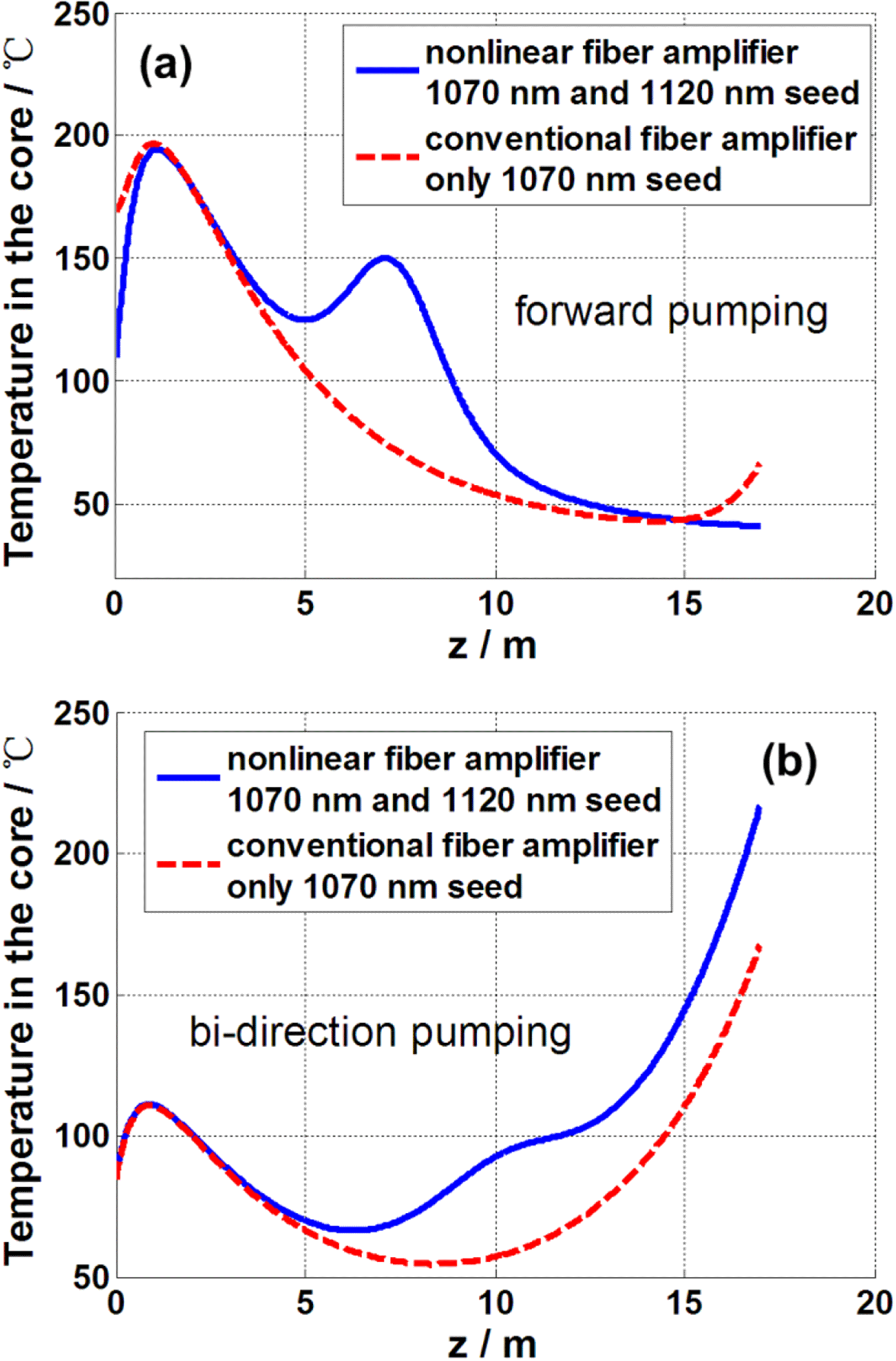
Figure 5. The center temperature of the core for NFA and conventional amplifier in (a) forward pumping scheme and (b) bi-direction pumping scheme. In the calculation, all the parameters of the bi-direction pumping scheme are the same as of the forward pumping scheme, excepting the pump power is divided equally into two directions.
We calculated the temperature distribution of the core center for the example proposed in Section 3.1, which is shown in Figure 5(a). The parameters used in the calculation are listed in Table 2. In the forward pumping scheme, the temperature distributed tendency of the NFA is similar with conventional fiber amplifier. The hottest point usually locates in the front part of the amplifier and the temperature gradually decreases along the fiber. But due to the further energy transfer from 1070 nm to 1120 nm, there is an additional energy loss in the middle of the YDF for the NFA, resulting in the temperature rising. The second temperature peak, however, is far lower (
![]() $50\,^{\circ }\text{C}$
in this case) than the original temperature peak. It means the NFA would not bring additional stable thermal burden for a uniform cooling high-power fiber laser system. So it still can work safely in conventional forward pumping fiber amplifier.
$50\,^{\circ }\text{C}$
in this case) than the original temperature peak. It means the NFA would not bring additional stable thermal burden for a uniform cooling high-power fiber laser system. So it still can work safely in conventional forward pumping fiber amplifier.
In the forward pumping NFA, the energy extraction can roundly divided into two parts. The first part is the amplification of the short signal wavelength laser (1070 nm), in which the ytterbium gain contributes more. And the second part is the nonlinear amplification, which requires the power of short signal wavelength laser to reach the nonlinear threshold. Consequently, the nonlinear effect induced energy transfer happens in the latter half of the fiber amplifier. But in the backward pumping or bi-direction pumping configurations, the nonlinearity related energy extraction and the Yb ions related amplification would be overlapped in the same piece of fiber, which will result in more thermal burden generation compared with conventional YDFA. Figure 5(b) is the center temperature in the core for a bi-direction pumping configuration with pump power of 4000 W in each side. At the output end, higher temperature can be found for the NFA. So in order to avoid additional thermal burden, NFA is suggested to apply the forward pumping scheme in high-power laser amplifier.

Figure 6. The experimental setup of the NFA[Reference Zhang, Xiao, Zhou, Wang and Xu34].
4 Experimental study on nonlinear fiber amplifier
4.1 Laser diode pumped high-power NFA
In recent years, laser diode pumped high-power NFA has been demonstrated by several independent groups. In this sub-section, we will generally review the high-power experimental result achieved in our group.
As a proof-of-concept demonstration, we built an NFA system as shown in Figure 6
[Reference Zhang, Xiao, Zhou, Wang and Xu34]. The seed is composed of fiber lasers working at 1070 nm and 1120 nm. The gain fiber in the amplifier stage is a 45-meters-long
![]() $20/400~\unicode[STIX]{x03BC}\text{m}$
YDF with a nominal cladding absorption coefficient of 1.3 dB/m. After the YDF, a pump dump is connected to stripe unabsorbed pump light and cladding mode. A home-made endcap is spliced in the end to avoid unwanted end reflection. The YDF is pumped by six 976 nm laser diodes with a total available power of 890 W. In the experiment, the 1120 nm laser power is 8 W and the total seed power is about 30 W. The measured total output power and 1120 nm power are shown in Figure 7. The 1120 nm power is achieved by integrated corresponding wavelength band in the output spectra. At the full pump power, the total output is 773 W and the maximum 1120 nm power is about 732 W. We also plotted the theoretical result by numerically solving the models proposed in Section 2 and shown in Figure 7, and it could be seen that the experimental results agree well with theoretical ones.
$20/400~\unicode[STIX]{x03BC}\text{m}$
YDF with a nominal cladding absorption coefficient of 1.3 dB/m. After the YDF, a pump dump is connected to stripe unabsorbed pump light and cladding mode. A home-made endcap is spliced in the end to avoid unwanted end reflection. The YDF is pumped by six 976 nm laser diodes with a total available power of 890 W. In the experiment, the 1120 nm laser power is 8 W and the total seed power is about 30 W. The measured total output power and 1120 nm power are shown in Figure 7. The 1120 nm power is achieved by integrated corresponding wavelength band in the output spectra. At the full pump power, the total output is 773 W and the maximum 1120 nm power is about 732 W. We also plotted the theoretical result by numerically solving the models proposed in Section 2 and shown in Figure 7, and it could be seen that the experimental results agree well with theoretical ones.

Figure 7. Theoretical prediction and experimental results of NFA.

Figure 8. Experimental result of 1.5 kW NFA[Reference Zhang, Tao, Zhou, Wang and Xu36].
After that we aim at more powerful NFA. The system shown in Figure 6 is redesigned[Reference Zhang, Tao, Zhou, Wang and Xu36]. The length of active fiber is shortened to be 26 m and the pump source is composed of two 976 nm LDs and four 915 nm LDs with maximum pump power of 2020 W. The experimental results are shown in Figure 8. The total output power increases nearly linearly with the pump power and so does the 1120 nm laser. The maximum output power is 1655 W when the 2010 W pump power is launched into the amplifier and the power of 1120 nm laser is about 1521 W with optical efficiency of 75.6%, which is the highest power reported in 1100–1200 nm range at that time. In the whole process of power scaling, the power of 1070 nm laser is less than 200 W and in the end only 96 W 1070 nm laser is residual in the output. The power ratio of 1120 nm laser turns from 30% to 96%, when the dual-wavelength seed passes through the amplifier as a result of the Raman amplification. The 3 dB bandwidth of the 1120 nm laser broadens from 0.35 nm to 1.4 nm when the LDs turned on. At the total output power of about 1 kW, a new wavelength peaking at 1175 nm starts to arise due to Raman-assisted-amplified FWM. The power proportion of this signal is only 0.7% at the full power. It is interesting that another two new wavelengths (1091 nm and 1149 nm) appear when the total output power is about 1.5 kW. The frequency differences of these two wavelengths to 1120 nm are equal, so we believe it is also caused by FWM. Though there are several new wavelengths in the output, the power ratio of 1120 nm laser still reaches 91.9%.
It is to be noted that the concept of NFA can be extended to polarization-maintained fiber amplification straightforwardly, and we have achieved an output power of 1181 W with polarization-extinction ratio (PER) of 18.2 dB[Reference Ma, Zhang, Huang, Wang, Zhou and Liu38].
4.2 Tandem-pumped high-power NFA
As indicated in previous discussions, NFA has the potential to break the power limitation induced by SRS during the power scaling process, and then the next power limitation might be the brightness of pump diode. In most of present high-power fiber laser systems, laser diodes are used as pump source. Recently, tandem pumping technique, which uses ‘fiber laser’ to pump active fiber, has been under intensive research, where the brightness of the pump laser is significantly increased[Reference Zhu, Zhou, Ma, Xu and Liu3, Reference Stiles46–Reference Xiao, Leng, Zhang, Huang, Xu and Zhou49]. In the present sub-section, we demonstrate the NFA in tandem pumping scheme for the first time.

Figure 9. The experimental setup of the tandem-pumped NFA.
As shown in Figure 9, the system setup of tandem-pumped NFA is similar to Figure 6. The seed is composed of fiber lasers working at 1090 nm and 1150 nm, and the output powers of those two lasers are 85 W and 7 W, respectively. The measured output power of the two waves at different pump power is shown in Figure 10(a). The power of 1090 nm and 1150 nm laser evolves to 65 W and 16 W after passing through the amplifier. This power level is below the Raman amplification threshold, which is estimated to be about hundreds of watts. Thus only Yb gain serves for the amplification of 1150 nm laser. It indicates that the 1150 nm laser also has the ability to extract energy from 1090 nm laser through Yb ions. The pump source is powerful 1018 nm fiber laser fabricated in our group[Reference Xiao, Zhou, Wang, Guo and Xu50–Reference Xiao, Zhou, Wang, Guo and Xu52], and the total available pump power is measured to be 1735 W in this experiment. The active fiber has
![]() $30~\unicode[STIX]{x03BC}\text{m}$
core diameter and
$30~\unicode[STIX]{x03BC}\text{m}$
core diameter and
![]() $250~\unicode[STIX]{x03BC}\text{m}$
inner cladding diameter, and the cladding absorption coefficient at 1018 nm is measured to be about
$250~\unicode[STIX]{x03BC}\text{m}$
inner cladding diameter, and the cladding absorption coefficient at 1018 nm is measured to be about
![]() $0.6~\text{dB}/\text{m}$
at a low power level, which is high enough thanks to the large pump overlap of the fiber. A piece of 38 m YDF is utilized to ensure adequate absorption. A pump stripper is spliced after the YDF to get rid of unwanted cladding light. Antireflection films are coated on the facet of the endcap to reduce backward reflection. The output lasers are collimated and separated by dichroic mirror for power and beam quality measurement.
$0.6~\text{dB}/\text{m}$
at a low power level, which is high enough thanks to the large pump overlap of the fiber. A piece of 38 m YDF is utilized to ensure adequate absorption. A pump stripper is spliced after the YDF to get rid of unwanted cladding light. Antireflection films are coated on the facet of the endcap to reduce backward reflection. The output lasers are collimated and separated by dichroic mirror for power and beam quality measurement.
When the pump power is injected, the total output power increases linearly with the change of the power ratio of the two waves. It should be noted that when the pump power is higher than 800 W, 1150 nm laser starts to increase fast while 1090 nm laser ceases rising. The 1150 nm laser gain mainly comes from the Raman amplification that becomes prominent as the power increases or waves propagate. Finally, the total output power is 1530 W with 1090 nm laser power of 703 W and 1150 nm laser power of 827 W. The power of 1150 nm laser is the highest one at this wavelength as we know. The output spectrum at full power is shown in Figure 10(b).
For comparison, we also conduct the experiment where only 1090 nm laser is seeded. It is a conventional tandem-pumped Yb-doped fiber amplifier, in which the 56 W seed could be linearly boosted to 1530 W, shown in Figure 11. The total output power is nearly the same as the NFA case. The slope efficiency of the YDFA and NFA is 85.7% and 83.5%, respectively. It can be found that the NFA works as efficiently as conventional YDFA. The difference mainly comes from the quantum defect of the energy conversion from 1090 nm laser to 1150 nm laser that is about 5%.
It is to be noted that most of the published literatures for YDFL focus on the common wavelength band such as 1070–1080 nm, whose operating power can achieve kilowatt level without too much difficulty. Because of the much smaller relative net gain and the significant amplified spontaneous emission at common band, lasing at 1120–1200 nm band (which also locates in the emission region of Yb-doped silica fiber) is much more challenging[Reference Kurkov, Paramonov and Medvedkov53–Reference Huang, Zhang, Wang and Zhou58]. Nevertheless, lasing at 1120–1200 nm band could find tremendous applications including biomedicine, new-style pump sources and remote sensing. Most of the demonstrated NFAs work at those wavelength bands, which provides a coincident solution for high-power laser source.
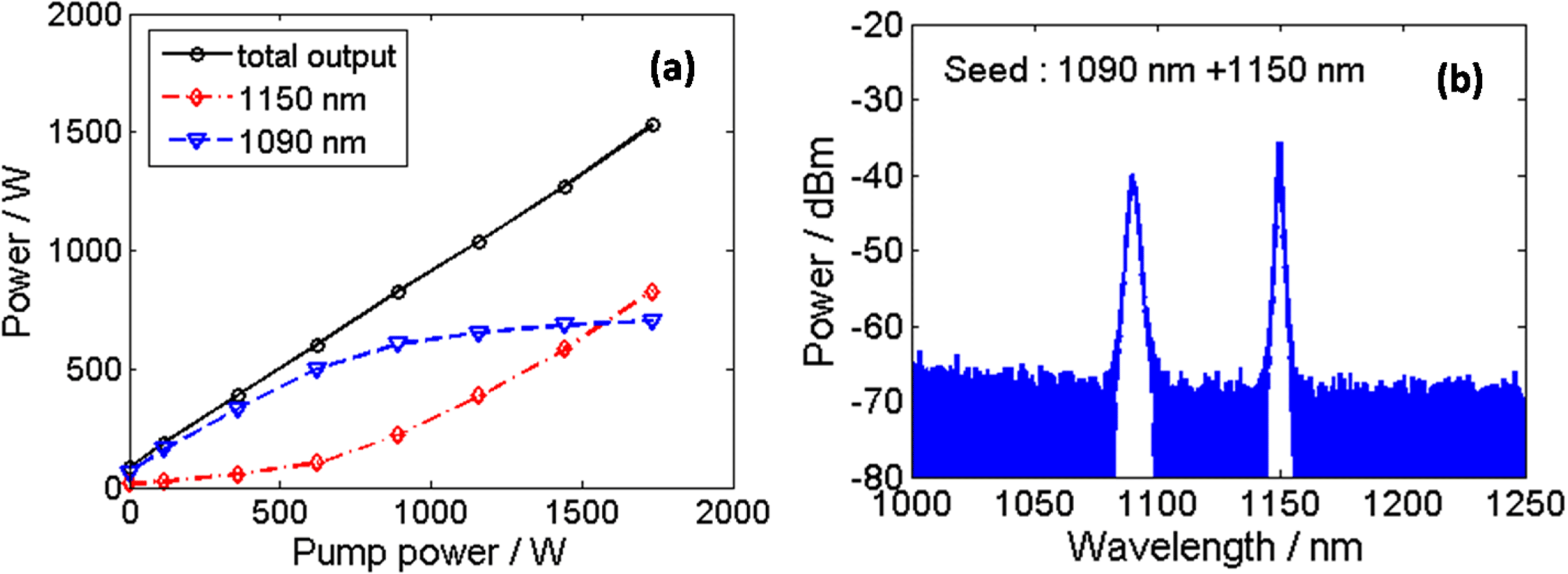
Figure 10. The output property of the tandem-pumped NFA: (a) output power; (b) spectrum at full power.
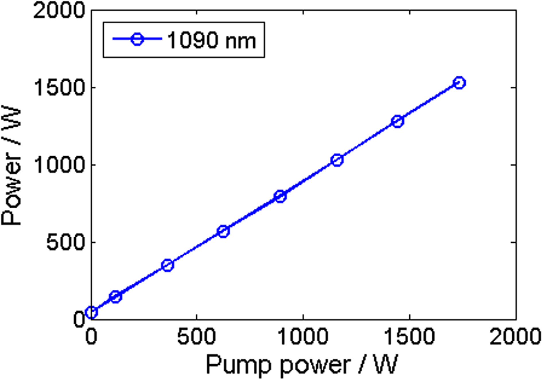
Figure 11. The measured 1090 nm laser power in the case of only 1090 nm seed with power of 56 W.
5 Discussion
In this section, we briefly discussed several new topics in high-power NFAs.
The first one is the FWM. In practical high-power NFA seeded by multi-wavelength laser, FWM might happen because the phase-mismatch could be compensated by the Yb gain[Reference Fève59]. In this case, the modeling of high-power NFA might be modified by taking FWM into consideration, which could be re-written as follows.
 $$\begin{eqnarray}\displaystyle \pm \frac{\text{d}E_{1}^{\pm }}{\text{d}z} & = & \displaystyle j\unicode[STIX]{x1D6FE}_{1}\{\!|E_{1}^{\pm }|^{2}+(2-\unicode[STIX]{x1D70C})[|E_{2}^{+}|^{2}\nonumber\\ \displaystyle & & \displaystyle +\,|E_{2}^{-}|^{2}+|E_{3}^{+}|^{2}+|E_{3}^{-}|^{2} ]\!\}E_{1}^{\pm }\nonumber\\ \displaystyle & & \displaystyle -\,\frac{g_{R1}\unicode[STIX]{x1D706}_{2}}{2\unicode[STIX]{x1D706}_{1}A}(|E_{2}^{+}|^{2}+|E_{2}^{-}|^{2})E_{1}^{\pm }\nonumber\\ \displaystyle & & \displaystyle +\,\frac{g_{1}(N_{2})}{2}E_{1}^{\pm }+j\unicode[STIX]{x1D6FE}_{1}E_{2}^{\pm }E_{2}^{\pm }E_{3}^{\pm \ast }e^{\pm j\unicode[STIX]{x0394}kz},\quad\end{eqnarray}$$
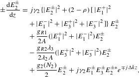 $$\begin{eqnarray}\displaystyle \pm \frac{\text{d}E_{2}^{\pm }}{\text{d}z} & = & \displaystyle j\unicode[STIX]{x1D6FE}_{2}\{\!|E_{2}^{\pm }|^{2}+(2-\unicode[STIX]{x1D70C})[|E_{1}^{+}|^{2}\nonumber\\ \displaystyle & & \displaystyle +\,|E_{1}^{-}|^{2}+|E_{3}^{+}|^{2}+|E_{3}^{-}|^{2} ]\!\}E_{2}^{\pm }\nonumber\\ \displaystyle & & \displaystyle +\,\frac{g_{R1}}{2A}(|E_{1}^{+}|^{2}+|E_{1}^{-}|^{2})E_{2}^{\pm }\nonumber\\ \displaystyle & & \displaystyle -\,\frac{g_{R2}\unicode[STIX]{x1D706}_{3}}{2\unicode[STIX]{x1D706}_{2}A}(|E_{3}^{+}|^{2}+|E_{3}^{-}|^{2})E_{2}^{\pm }\nonumber\\ \displaystyle & & \displaystyle +\,\frac{g_{2}(N_{2})}{2}E_{2}^{\pm }+j\unicode[STIX]{x1D6FE}_{2}E_{1}^{\pm }E_{3}^{\pm }E_{2}^{\pm \ast }e^{\mp j\unicode[STIX]{x0394}kz},\end{eqnarray}$$
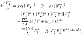 $$\begin{eqnarray}\displaystyle \pm \frac{\text{d}E_{3}^{\pm }}{\text{d}z} & = & \displaystyle j\unicode[STIX]{x1D6FE}_{3}\{\!|E_{3}^{\pm }|^{2}+(2-\unicode[STIX]{x1D70C})[|E_{1}^{+}|^{2}\nonumber\\ \displaystyle & & \displaystyle +\,|E_{1}^{-}|^{2}+|E_{2}^{+}|^{2}+|E_{2}^{-}|^{2} ]\!\}E_{3}^{\pm }\nonumber\\ \displaystyle & & \displaystyle +\,\frac{g_{R2}}{2A}(|E_{2}^{+}|^{2}+|E_{2}^{-}|^{2})E_{3}^{\pm }\nonumber\\ \displaystyle & & \displaystyle +\,\frac{g_{3}(N_{2})}{2}E_{3}^{\pm }+j\unicode[STIX]{x1D6FE}_{3}E_{2}^{\pm }E_{2}^{\pm }E_{1}^{\pm \ast }e^{\pm j\unicode[STIX]{x0394}kz},\end{eqnarray}$$
 $$\begin{eqnarray}\displaystyle & & \displaystyle N_{2}(z)=\frac{\displaystyle \frac{N_{0}}{Ahc}\mathop{\sum }_{k}\unicode[STIX]{x1D6E4}_{k}\unicode[STIX]{x1D706}_{k}\unicode[STIX]{x1D70E}_{a}(\unicode[STIX]{x1D706}_{k})(P_{k}^{+}+P_{k}^{-})}{\displaystyle \frac{1}{\unicode[STIX]{x1D70F}}+\displaystyle \frac{N_{0}}{Ahc}\mathop{\sum }_{k}\unicode[STIX]{x1D6E4}_{k}\unicode[STIX]{x1D706}_{k}(P_{k}^{+}+P_{k}^{-})[\unicode[STIX]{x1D70E}_{a}(\unicode[STIX]{x1D706}_{k})+\unicode[STIX]{x1D70E}_{e}(\unicode[STIX]{x1D706}_{k})]}\nonumber\\ \displaystyle & & \displaystyle \quad (k=p,1,2,3),\end{eqnarray}$$
The superscript
![]() $\pm$
corresponds to positive and negative directions, respectively. The subscript
$\pm$
corresponds to positive and negative directions, respectively. The subscript
![]() $k=p,1,2,3$
represents the pump, signal, first-order and second-order Stokes waves, respectively. The complex electric-field envelope
$k=p,1,2,3$
represents the pump, signal, first-order and second-order Stokes waves, respectively. The complex electric-field envelope
![]() $E_{i}(z)=A_{i}(z)e^{j\unicode[STIX]{x1D711}(z)}$
is related to power by
$E_{i}(z)=A_{i}(z)e^{j\unicode[STIX]{x1D711}(z)}$
is related to power by
![]() $P_{i}(z)=A_{i}^{2}(z)$
. The terms on the right-hand side of Equations (10)–(12) describe, respectively, self- and cross-phase modulation, SRS, amplification, and FWM.
$P_{i}(z)=A_{i}^{2}(z)$
. The terms on the right-hand side of Equations (10)–(12) describe, respectively, self- and cross-phase modulation, SRS, amplification, and FWM.
![]() $\unicode[STIX]{x1D70C}$
is the fractional Raman contribution (typically
$\unicode[STIX]{x1D70C}$
is the fractional Raman contribution (typically
![]() $\unicode[STIX]{x1D70C}=0.18$
in silica), and
$\unicode[STIX]{x1D70C}=0.18$
in silica), and
![]() $\unicode[STIX]{x1D6FE}$
is the nonlinear coefficient.
$\unicode[STIX]{x1D6FE}$
is the nonlinear coefficient.
![]() $\unicode[STIX]{x0394}k$
is the phase-mismatch.
$\unicode[STIX]{x0394}k$
is the phase-mismatch.
![]() $g_{k}$
is the rare-earth-ion gain. The definitions of other symbols are the same as the model proposed in Section 2.
$g_{k}$
is the rare-earth-ion gain. The definitions of other symbols are the same as the model proposed in Section 2.
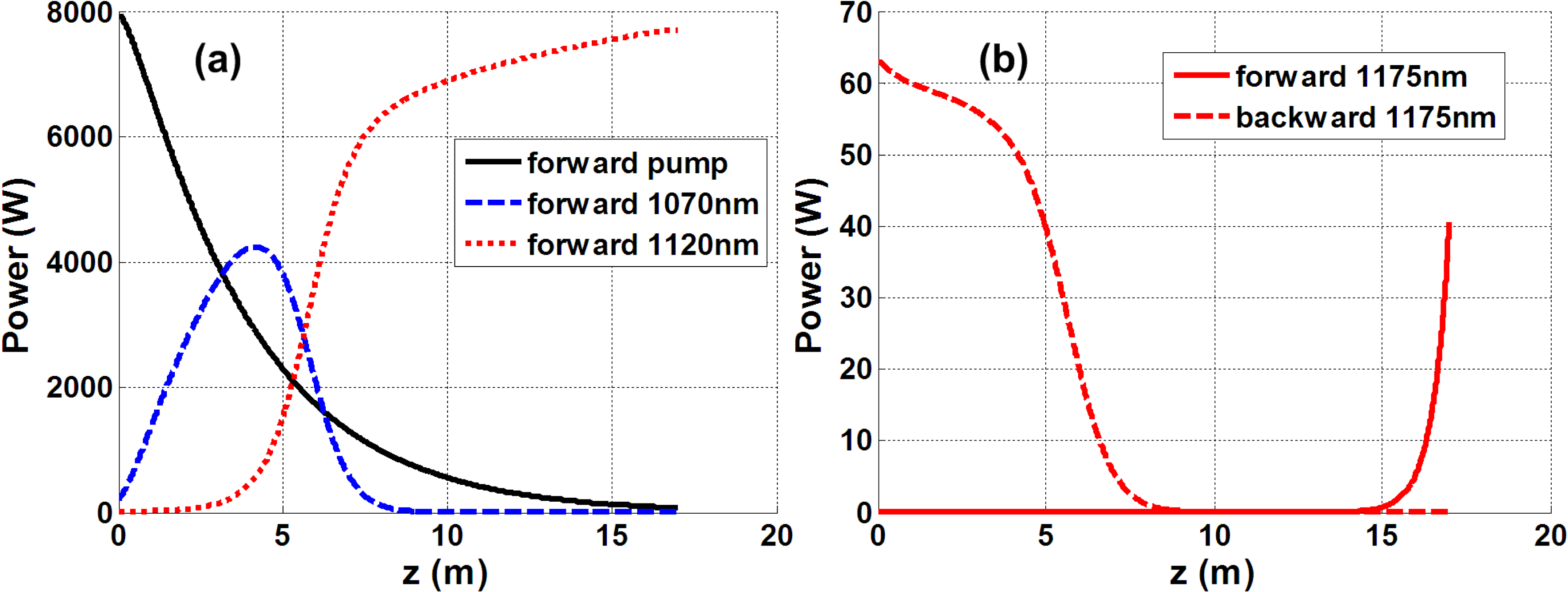
Figure 12. The power distribution of the NFA example proposed in Section 3.1 calculated by the FWM model.
The boundary conditions can be described by the following equations.
![]() $P_{0}^{\pm }(\unicode[STIX]{x1D706}_{k})$
is the initially injected power of wavelength
$P_{0}^{\pm }(\unicode[STIX]{x1D706}_{k})$
is the initially injected power of wavelength
![]() $\unicode[STIX]{x1D706}_{k}$
. Assuming
$\unicode[STIX]{x1D706}_{k}$
. Assuming
![]() $P_{0}^{\pm }(\unicode[STIX]{x1D706}_{k})$
equals the thermal noise, i.e.,
$P_{0}^{\pm }(\unicode[STIX]{x1D706}_{k})$
equals the thermal noise, i.e.,
![]() $2hv_{k}\unicode[STIX]{x0394}v_{k}$
, if there is no power injected, here
$2hv_{k}\unicode[STIX]{x0394}v_{k}$
, if there is no power injected, here
![]() $\unicode[STIX]{x0394}v_{3}$
should be equal to
$\unicode[STIX]{x0394}v_{3}$
should be equal to
![]() $\unicode[STIX]{x0394}v_{1}$
because the interacted wavelengths have to satisfy the same frequency interval and similar bandwidth.
$\unicode[STIX]{x0394}v_{1}$
because the interacted wavelengths have to satisfy the same frequency interval and similar bandwidth.
In order to evaluate the influence of FWM in the NFA, we calculate again the example proposed in Section 3.1 with the same parameters, except that the second-order Raman Stokes wavelength is 1175 nm. In addition, we take
![]() $\unicode[STIX]{x1D6FE}=0.45\times 10^{-3}~\text{m}^{-1}\,\cdot \,\text{W}^{-1}$
,
$\unicode[STIX]{x1D6FE}=0.45\times 10^{-3}~\text{m}^{-1}\,\cdot \,\text{W}^{-1}$
,
![]() $\unicode[STIX]{x0394}k=200~\text{m}^{-1}$
, and
$\unicode[STIX]{x0394}k=200~\text{m}^{-1}$
, and
![]() $\unicode[STIX]{x0394}v_{3}=\unicode[STIX]{x0394}v_{1}=0.3~\text{THz}$
in the calculation.
$\unicode[STIX]{x0394}v_{3}=\unicode[STIX]{x0394}v_{1}=0.3~\text{THz}$
in the calculation.
Figure 12 is the calculated power distribution. The power evolution of the involved waves is nearly the same as the results shown in Figure 3(a). The power of the second-order Stokes wave, however, is an order of magnitude higher than previous calculation. We also find that if the 1120 nm seed power reduced to 0.5 W, the output power of 1175 nm could decrease to 6 W in both directions. It means the rare-earth-ion gain induced FWM would intensively affect the energy transfer in the NFA under some conditions. So the problems, such as how to reduce the influence of FWM, whether FWM effect is still obvious if the second-order Stokes wave is beyond the gain spectrum of the rare-earth ion, should be carefully studied.
The second one is MI. We have to note that MI has become a serious challenge for further scaling the output power[Reference Johansen, Hansen, Alkeskjold and Lægsgaard60–Reference Tao, Ma, Wang, Zhou and Liu67]. Generally, MI could be attributed to the power coupling between fundamental mode and high-order mode supported by the fiber waveguide. Theoretical and experimental results have proved that the MI threshold would be higher if the core diameter of the active fiber is smaller[Reference Johansen, Hansen, Alkeskjold and Lægsgaard60, Reference Tao, Ma, Wang, Zhou and Liu65]. In this case, tandem-pumped NFA, where larger-mode-area fiber is preferred to ensure sufficient absorption, would encounter complex nonlinear effect, i.e., the MI effect trends to transfer power to high-order mode, while the Raman gain provided by the NFA simultaneously has a self-cleaning effect that is apt to lower mode operation. MI in pure cladding pumped Raman fiber laser has been investigated[Reference Naderi, Dajani, Grosek and Madden66], and thus the coupling between MI and Yb/Raman might have plenty nonlinear dynamics that should be further investigated.
The third one is PD effect. Since SRS effect suppression is no longer required, highly doped fiber, which is often used to shorten the fiber length, is also not required in high-power NFA. Moderately or lowly doped active fiber could be employed and thus PD effect suppression could be expected in NFA. However, as shown in Section 3.3, there is intrinsic difference in heat distribution inside the NFA, and the effect of the new heat generation mechanism on PD is an interesting topic. PD in NFA might also affect the MI threshold that has been observed in YDFA[Reference Laurila, Jørgensen, Hansen, Alkeskjold, Broeng and Lægsgaard68].
Last but not the least, NFA in different wavelength bands, for example,
![]() $2~\unicode[STIX]{x03BC}\text{m}$
band, has also been achieved[Reference Liu, Tan, Shi and Wang40]. We have to note that up to now there are no theoretical predictions. It is known that lasing at
$2~\unicode[STIX]{x03BC}\text{m}$
band, has also been achieved[Reference Liu, Tan, Shi and Wang40]. We have to note that up to now there are no theoretical predictions. It is known that lasing at
![]() ${>}2.1~\unicode[STIX]{x03BC}\text{m}$
is more difficult for Tm-doped fiber than for Ho-doped fiber[Reference Jin, Du, Wang, Zhou, Zhang, Wan and Liu69], however, Tm-doped fiber is relatively more mature than its Ho-doped counterpart[Reference Wang, Geng and Jiang70–Reference Wang, Zhou, Wang, Xiao and Si72]. In this case, it is worthwhile to study the feasibility of obtaining high-power laser at
${>}2.1~\unicode[STIX]{x03BC}\text{m}$
is more difficult for Tm-doped fiber than for Ho-doped fiber[Reference Jin, Du, Wang, Zhou, Zhang, Wan and Liu69], however, Tm-doped fiber is relatively more mature than its Ho-doped counterpart[Reference Wang, Geng and Jiang70–Reference Wang, Zhou, Wang, Xiao and Si72]. In this case, it is worthwhile to study the feasibility of obtaining high-power laser at
![]() ${>}2.1~\unicode[STIX]{x03BC}\text{m}$
band based on Tm/Raman NFA. The potential in power scaling of mid-infrared fiber laser[Reference Jackson73] based on rare-earth ion and Raman gain is another interesting topic.
${>}2.1~\unicode[STIX]{x03BC}\text{m}$
band based on Tm/Raman NFA. The potential in power scaling of mid-infrared fiber laser[Reference Jackson73] based on rare-earth ion and Raman gain is another interesting topic.
6 Conclusion
Through theoretical investigation and experimental validation, it can be seen that NFA fully explores the power scaling potential of both rare-earth ions and SRS in cladding pumped fibers, while simultaneously settled the power limitation and hazard induced by SRS in classical high-power fiber laser system, and it opens a new physically straightforward and technically feasible solution for obtaining ultra-high-power fiber lasers. Tremendous study might be illuminated by this concept to develop high-power fiber laser system. In addition, the plenty new physical insight within the amplifier that includes several nonlinear optical effects coupled with each other also might be interesting for theoretical studies.
Acknowledgements
This work was supported by the Natural Science Foundation of Hunan Province, China (No. 2018JJ2474) and the Huo Yingdong Education Foundation of China.


