1. Introduction
Recently, there has been a resurgence of interest in rare-earth (RE) doped YAG (RE:YAG) transparent ceramics as laser gain media, because the optical quality of the ceramics has been greatly improved. It is now comparable to that of single-crystal materials[Reference Messing and Stevenson1, Reference Ikesue and Aung2]. Compared with singlecrystal-based laser materials, apart from possessing exactly the same spectroscopic properties, ceramic laser materials also have the advantages of ease to fabricate large size and complicated structures, short fabrication time, and the possibility of mass production.
Polycrystalline ceramics became available for optical applications in 1962, when Coble first prepared translucent ![]() ${\rm Al}_{2}{\rm O}_{3}$ ceramics[Reference Coble3]. Since then, various kinds of transparent ceramics have been developed for optical and related applications. In 1995, Ikesue et al. achieved highly efficient continuous-wave (CW) laser emission in a Nd:YAG transparent ceramic[Reference Ikesue, Kinoshita, Kamata and Yoshida4–Reference Ikesue, Kamata and Yoshida6]. They fabricated transparent polycrystalline Nd:YAG ceramics by a solid-state reactive sintering method using high-purity powders as the starting materials. A laser output of about 70 mW was obtained with a slope efficiency of 28%. Their result clearly demonstrated the potential high functionality and flexibility of the laser ceramics. Since 1999, Yagi’s group in Konoshima Chemical and Ueda’s group in the University of Electrocommunications, Japan, have developed highly transparent ceramic laser materials in different ways: using nanopowder technology and using a vacuum sintering method. Scattering losses were greatly reduced in Konoshima’s YAG transparent laser ceramics[Reference Lu, Prabhu and Song7, Reference Lu, Song and Prabhu8]. In 2000 and 2001, Lu et al. reported the operation of diode pump Nd:YAG ceramic lasers with ceramic samples made by Konoshima Chemical. The output power was gradually increased from 31 W to 110 W[Reference Lu, Song and Prabhu8–Reference Lu, Yagi and Takaichi11]. Extensive studies have shown that the thermal and mechanical properties of the ceramics are better than those of YAG single crystals[Reference Maziex and Green12, Reference Yagi, Takaichi, Ueda, Yamasaki, Yanagitani and Kaminskii13]. In 2006, the Lawrence Livermore National Laboratory (LLNL) succeeded in achieving a world record high power of 67 kW emission from its solid-state heat capacity laser system using a large-scale transparent Nd:YAG ceramic with samarium edge cladding supplied by Konoshima Chemical[Reference Yamanoto14]. Very recently, the emission of a Nd:YAG ceramic laser system with output power beyond 100 kW was further demonstrated[Reference Bishop15–Reference Guoguang and Yunian17].
${\rm Al}_{2}{\rm O}_{3}$ ceramics[Reference Coble3]. Since then, various kinds of transparent ceramics have been developed for optical and related applications. In 1995, Ikesue et al. achieved highly efficient continuous-wave (CW) laser emission in a Nd:YAG transparent ceramic[Reference Ikesue, Kinoshita, Kamata and Yoshida4–Reference Ikesue, Kamata and Yoshida6]. They fabricated transparent polycrystalline Nd:YAG ceramics by a solid-state reactive sintering method using high-purity powders as the starting materials. A laser output of about 70 mW was obtained with a slope efficiency of 28%. Their result clearly demonstrated the potential high functionality and flexibility of the laser ceramics. Since 1999, Yagi’s group in Konoshima Chemical and Ueda’s group in the University of Electrocommunications, Japan, have developed highly transparent ceramic laser materials in different ways: using nanopowder technology and using a vacuum sintering method. Scattering losses were greatly reduced in Konoshima’s YAG transparent laser ceramics[Reference Lu, Prabhu and Song7, Reference Lu, Song and Prabhu8]. In 2000 and 2001, Lu et al. reported the operation of diode pump Nd:YAG ceramic lasers with ceramic samples made by Konoshima Chemical. The output power was gradually increased from 31 W to 110 W[Reference Lu, Song and Prabhu8–Reference Lu, Yagi and Takaichi11]. Extensive studies have shown that the thermal and mechanical properties of the ceramics are better than those of YAG single crystals[Reference Maziex and Green12, Reference Yagi, Takaichi, Ueda, Yamasaki, Yanagitani and Kaminskii13]. In 2006, the Lawrence Livermore National Laboratory (LLNL) succeeded in achieving a world record high power of 67 kW emission from its solid-state heat capacity laser system using a large-scale transparent Nd:YAG ceramic with samarium edge cladding supplied by Konoshima Chemical[Reference Yamanoto14]. Very recently, the emission of a Nd:YAG ceramic laser system with output power beyond 100 kW was further demonstrated[Reference Bishop15–Reference Guoguang and Yunian17].
In the past years, most of the research work on transparent laser ceramics has focused on Nd:YAG ceramics. Recently, some research groups have also paid attention to developing other rare-earth doped YAG ceramics, such as Yb:YAG, Er:YAG, Ho:YAG, the sesquioxide ceramics ![]() $({\rm Y}_{2}{\rm O}_{3}, {\rm Lu}_{2}{\rm O}_{3}, {\rm Sc}_{2}{\rm O}_{3})$, and composite ceramics. Dong et al. reported continuous-wave and passively Q-switched microchip lasers made of Yb:YAG ceramics[Reference Dong, Xu and Ma18]. Heavily doped Yb:YAG ceramics are more suitable for thin disk lasers than Yb:YAG single crystal. Sesquioxides possess higher thermal conductivities than YAG. For high-power lasers, thermal conductivity is an important parameter of the laser gain media. Kim et al. reported the fabrication of
$({\rm Y}_{2}{\rm O}_{3}, {\rm Lu}_{2}{\rm O}_{3}, {\rm Sc}_{2}{\rm O}_{3})$, and composite ceramics. Dong et al. reported continuous-wave and passively Q-switched microchip lasers made of Yb:YAG ceramics[Reference Dong, Xu and Ma18]. Heavily doped Yb:YAG ceramics are more suitable for thin disk lasers than Yb:YAG single crystal. Sesquioxides possess higher thermal conductivities than YAG. For high-power lasers, thermal conductivity is an important parameter of the laser gain media. Kim et al. reported the fabrication of ![]() $\text {Yb:Lu}_{2}{\rm O}_{3}$ transparent ceramic by a hot isostatic pressing (HIP) approach[Reference Kim, Baker and Villalobos19]. They successfully demonstrated efficient lasing with fabricated
$\text {Yb:Lu}_{2}{\rm O}_{3}$ transparent ceramic by a hot isostatic pressing (HIP) approach[Reference Kim, Baker and Villalobos19]. They successfully demonstrated efficient lasing with fabricated ![]() $\text {Yb:Lu}_{2}{\rm O}_{3}$ ceramic. An output power of more than 16 W at 1080 nm was obtained with a slope efficiency of 74%. Ikesue et al. demonstrated laser-quality composite transparent ceramics by using a layer by layer approach[Reference Ikesue and Aung2]. Messing et al. developed a colloidal tape casting process to make composite laser ceramics. A ceramic rod with segments of undoped YAG, 0.25% Er:YAG, and 0.5% Er:YAG was fabricated. With such a composite ceramic rod of length 62 mm, lasing with a slope efficiency of 27% was achieved, compared with the 39% slope efficiency achieved on a commercial 45 mm long 0.5% Er:YAG single crystal rod[Reference Kupp, Messing, Anderson and Gopalan20].
$\text {Yb:Lu}_{2}{\rm O}_{3}$ ceramic. An output power of more than 16 W at 1080 nm was obtained with a slope efficiency of 74%. Ikesue et al. demonstrated laser-quality composite transparent ceramics by using a layer by layer approach[Reference Ikesue and Aung2]. Messing et al. developed a colloidal tape casting process to make composite laser ceramics. A ceramic rod with segments of undoped YAG, 0.25% Er:YAG, and 0.5% Er:YAG was fabricated. With such a composite ceramic rod of length 62 mm, lasing with a slope efficiency of 27% was achieved, compared with the 39% slope efficiency achieved on a commercial 45 mm long 0.5% Er:YAG single crystal rod[Reference Kupp, Messing, Anderson and Gopalan20].
2. Fabrication of YAG laser ceramics
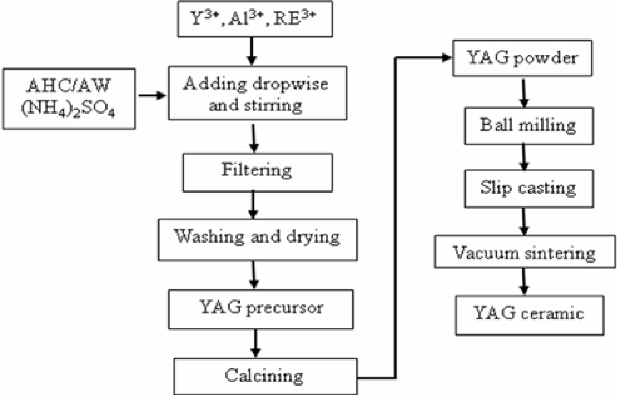
Suitable fabrication methods are required to obtain YAG transparent ceramics of ![]() $>$99.99% density. So far, two different approaches have been successfully implemented to produce high-quality laser ceramics. Figure 1 shows the fabrication process for YAG transparent ceramics by the co-precipitation and vacuum sintering method[Reference Yagi, Yanagitani, Takaichi, Ueda and Kaminskii21]. Konoshima Chemical succeeded in fabricating high-quality transparent YAG-based laser ceramics using this method. The method is based on co-precipitation of a metal nitrate solution with
$>$99.99% density. So far, two different approaches have been successfully implemented to produce high-quality laser ceramics. Figure 1 shows the fabrication process for YAG transparent ceramics by the co-precipitation and vacuum sintering method[Reference Yagi, Yanagitani, Takaichi, Ueda and Kaminskii21]. Konoshima Chemical succeeded in fabricating high-quality transparent YAG-based laser ceramics using this method. The method is based on co-precipitation of a metal nitrate solution with ![]() ${\rm NH}_{4}{\rm HCO}_{3}$. Aqueous solutions of aluminum, yttrium and rare-earth nitrates are mixed together. The mixed aqueous solution is added dropwise and mixed with an aqueous solution of
${\rm NH}_{4}{\rm HCO}_{3}$. Aqueous solutions of aluminum, yttrium and rare-earth nitrates are mixed together. The mixed aqueous solution is added dropwise and mixed with an aqueous solution of ![]() ${\rm NH}_{4}{\rm HCO}_{3}$. Steps of filtration and washing with water are repeated several times, and the resulting material is then dried for 2 days at
${\rm NH}_{4}{\rm HCO}_{3}$. Steps of filtration and washing with water are repeated several times, and the resulting material is then dried for 2 days at ![]() $\sim 120^{\circ }{\rm C}$. The precursor thus obtained is calcined at
$\sim 120^{\circ }{\rm C}$. The precursor thus obtained is calcined at ![]() $1200^{\circ }{\rm C}$, and then the YAG powder is obtained. This powder is milled with solvent, binder and dispersion medium for 24 hours. The milled slurry is put in a gypsum mold and dried to obtain the desired form, or the slip casting forming method is used to obtain a high-density and uniformly green body. After removing the organic component by calcining, such material is vacuum sintered at
$1200^{\circ }{\rm C}$, and then the YAG powder is obtained. This powder is milled with solvent, binder and dispersion medium for 24 hours. The milled slurry is put in a gypsum mold and dried to obtain the desired form, or the slip casting forming method is used to obtain a high-density and uniformly green body. After removing the organic component by calcining, such material is vacuum sintered at ![]() $1700^{\circ }{\rm C}$; then highly transparent Nd:YAG ceramics can be obtained.
$1700^{\circ }{\rm C}$; then highly transparent Nd:YAG ceramics can be obtained.

Figure 1. Fabrication process of YAG ceramic by co-precipitation and vacuum sintering method.
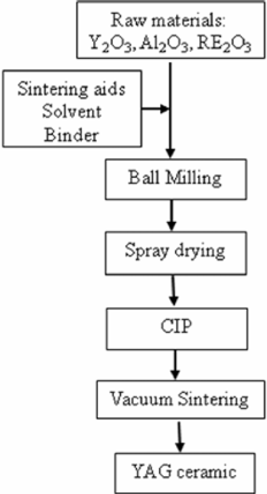
Ikesue reported laser-quality polycrystalline Nd:YAG transparent ceramics made using a reactive sintering method. Figure 2 shows the fabrication process of the method[Reference Ikesue, Kinoshita, Kamata and Yoshida4]. Commercial ![]() $\alpha \text {-}{\rm Al}_{2}{\rm O}_{3}, {\rm Y}_{2}{\rm O}_{3}$, and
$\alpha \text {-}{\rm Al}_{2}{\rm O}_{3}, {\rm Y}_{2}{\rm O}_{3}$, and ![]() ${\rm RE}_{2}{\rm O}_{3}$ powders are selected as the starting materials. The powders are weighed precisely according to the chemical stoichiometric composition and mixed with 99.99% ethanol. The mixed slurry is then ball milled using a planetary milling machine for 15 hours. TEOS is introduced at 0.5 wt% relative to the total powder mass to introduce
${\rm RE}_{2}{\rm O}_{3}$ powders are selected as the starting materials. The powders are weighed precisely according to the chemical stoichiometric composition and mixed with 99.99% ethanol. The mixed slurry is then ball milled using a planetary milling machine for 15 hours. TEOS is introduced at 0.5 wt% relative to the total powder mass to introduce ![]() ${\rm SiO}_{2}$ as a sintering aid. After milling, the powder mixture is dried at
${\rm SiO}_{2}$ as a sintering aid. After milling, the powder mixture is dried at ![]() $120^{\circ }{\rm C}$ for 24 hours in an oven and then sieved through a 200-mesh screen. After removing organic components by calcining at
$120^{\circ }{\rm C}$ for 24 hours in an oven and then sieved through a 200-mesh screen. After removing organic components by calcining at ![]() $800^{\circ }{\rm C}$ for 3 hours, the powders are dry pressed in a stainless steel die at 15 MPa. The green body pellets are further cold isostatically pressed (CIP) at 200 MPa. After CIP, the relative density of the green body is
$800^{\circ }{\rm C}$ for 3 hours, the powders are dry pressed in a stainless steel die at 15 MPa. The green body pellets are further cold isostatically pressed (CIP) at 200 MPa. After CIP, the relative density of the green body is ![]() $\sim $53%. The green bodies are sintered in a high temperature vacuum sintering furnace. The sintered pellets are then annealed in air at
$\sim $53%. The green bodies are sintered in a high temperature vacuum sintering furnace. The sintered pellets are then annealed in air at ![]() $1400^{\circ }{\rm C}$ for 15 hours to completely remove internal stress and eliminate the oxygen vacancies. After polishing, the specimen can be used as a laser medium.
$1400^{\circ }{\rm C}$ for 15 hours to completely remove internal stress and eliminate the oxygen vacancies. After polishing, the specimen can be used as a laser medium.

Figure 2. Fabrication process of YAG ceramic by reactive sintering method.

Figure 3. Photograph of different rare-earth doped YAG transparent ceramics fabricated in-house.

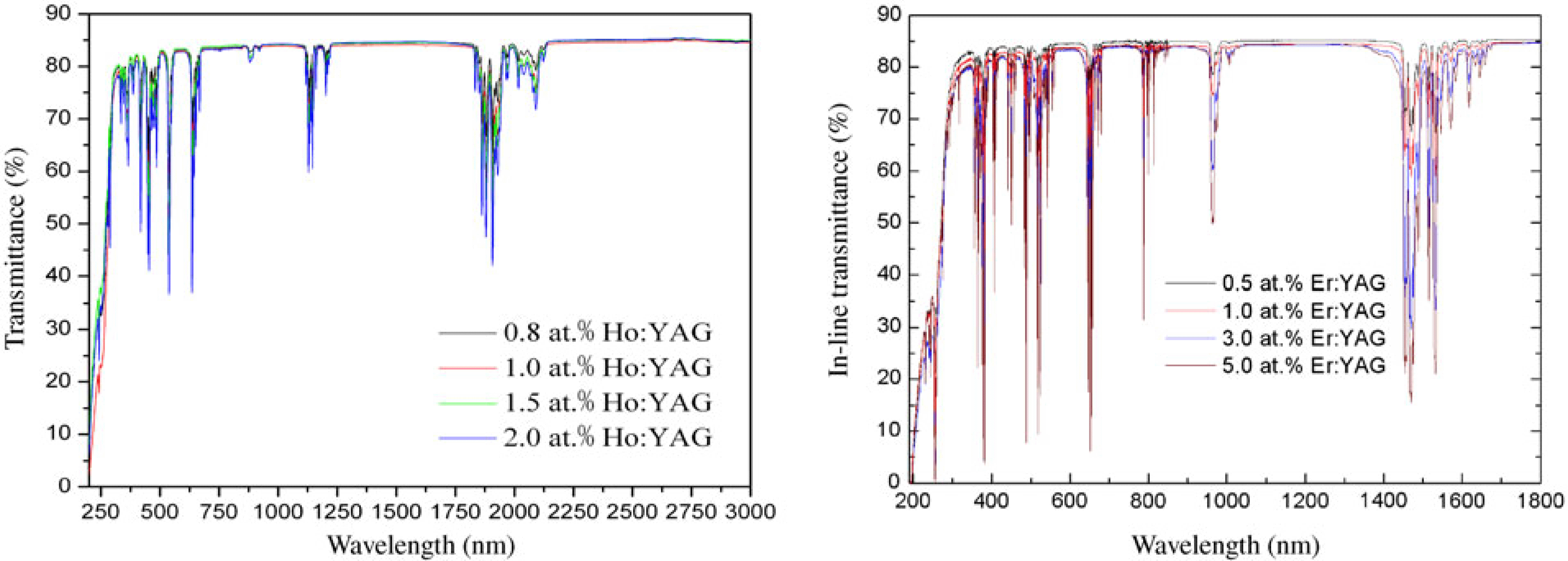
Figure 4. The in-line transmittance of Ho:YAG and Er:YAG transparent ceramics with different doping concentrations.

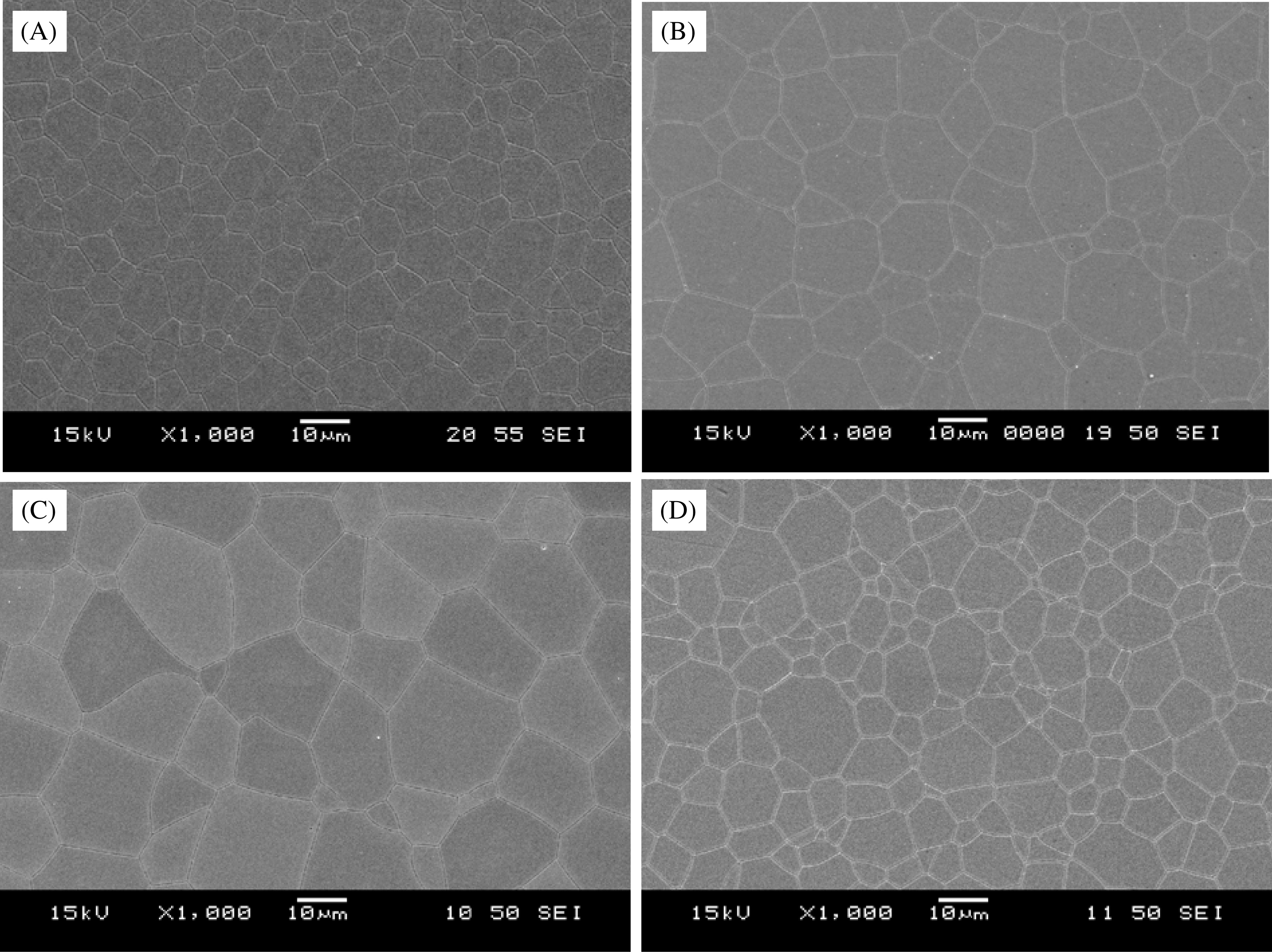
Figure 5. The microstructures of the RE:YAG ceramics fabricated in-house: (A) Er:YAG, (B) Ho:YAG, (C) Tm:YAG, and (D) Nd:YAG.

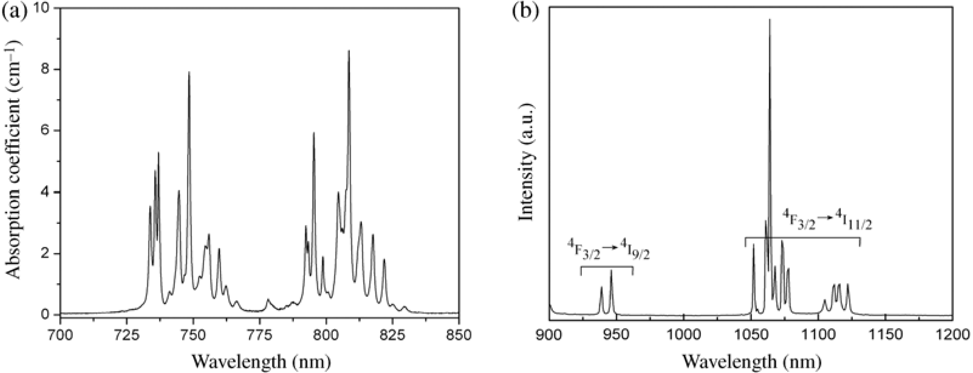
Figure 6. The absorption and emission spectra of the fabricated Nd:YAG ceramics.
3. Properties of the RE:YAG ceramics
Using the reactive sintering method, we have succeeded in fabricating high-quality transparent YAG ceramics doped with different rare-earth ions such as ![]() ${\rm Nd}^{3+}$,
${\rm Nd}^{3+}$, ![]() ${\rm Yb}^{3+}$,
${\rm Yb}^{3+}$, ![]() ${\rm Er}^{3+}$,
${\rm Er}^{3+}$, ![]() ${\rm Ho}^{3+}$ and
${\rm Ho}^{3+}$ and ![]() ${\rm Tm}^{3+}$[Reference Gong, Tang, Huang and Ma22–Reference Gao, Ma and Xie28]. Figure 3 shows a photograph of various rare-earth-ion doped YAG ceramics fabricated in-house. To illustrate the high optical quality of the fabricated YAG ceramics, as examples, we have shown in Figure 4 the optical transmission of
${\rm Tm}^{3+}$[Reference Gong, Tang, Huang and Ma22–Reference Gao, Ma and Xie28]. Figure 3 shows a photograph of various rare-earth-ion doped YAG ceramics fabricated in-house. To illustrate the high optical quality of the fabricated YAG ceramics, as examples, we have shown in Figure 4 the optical transmission of ![]() ${\rm Er}^{3+}$ and
${\rm Er}^{3+}$ and ![]() ${\rm Ho}^{3+}$ doped YAG under different doping concentrations. The transmittance of all the ceramics at 1100 nm is above 84%, which is very close to the theoretic transmittance.
${\rm Ho}^{3+}$ doped YAG under different doping concentrations. The transmittance of all the ceramics at 1100 nm is above 84%, which is very close to the theoretic transmittance.
Grain sizes, grain-boundary phases, and pores are usually considered as the main factors affecting the optical quality of transparent ceramics. Figure 5 shows the microstructures of YAG ceramics doped with different types of rare-earth ion after thermal etching at ![]() $1500^{\circ }{\rm C}$ for 1 hour. The transparent ceramics are composed of grains with an average size
$1500^{\circ }{\rm C}$ for 1 hour. The transparent ceramics are composed of grains with an average size ![]() $\sim 10\ \mathrm {\mu} {\rm m}$. It can be seen that the grain size changed very little with the different types of rare-earth-ion doping. No grain-boundary phases and pores can be observed in the microstructures of the RE:YAG ceramics.
$\sim 10\ \mathrm {\mu} {\rm m}$. It can be seen that the grain size changed very little with the different types of rare-earth-ion doping. No grain-boundary phases and pores can be observed in the microstructures of the RE:YAG ceramics.
4. Laser performance of the fabricated ceramics
There has been extensive research on the lasing performance of Nd:YAG and Yb:YAG ceramics, not only because high optical quality Nd:YAG ceramics were successfully produced, but also because their single-crystal counterparts have been widely used in commercial solid-state laser systems. ![]() ${\rm Nd}^{3+}$ or
${\rm Nd}^{3+}$ or ![]() ${\rm Yb}^{3+}$ doped lasers emit in the
${\rm Yb}^{3+}$ doped lasers emit in the ![]() $1.0\ \mathrm {\mu} {\rm m}$ wavelength regime. High-power solid-state lasers operating in this wavelength regime have found widespread applications in various fields ranging from industrial materials processing to medical devices. Compared with
$1.0\ \mathrm {\mu} {\rm m}$ wavelength regime. High-power solid-state lasers operating in this wavelength regime have found widespread applications in various fields ranging from industrial materials processing to medical devices. Compared with ![]() ${\rm Nd}^{3+}$ and
${\rm Nd}^{3+}$ and ![]() ${\rm Yb}^{3+}$ ion doped YAG ceramics,
${\rm Yb}^{3+}$ ion doped YAG ceramics, ![]() ${\rm Er}^{3+}, {\rm Tm}^{3+}$, and
${\rm Er}^{3+}, {\rm Tm}^{3+}$, and ![]() ${\rm Ho}^{3+}$ doped YAG ceramics emit in the 1.5–
${\rm Ho}^{3+}$ doped YAG ceramics emit in the 1.5–![]() $2.0\ \mathrm {\mu} {\rm m}$ wavelength regime. 1.5–
$2.0\ \mathrm {\mu} {\rm m}$ wavelength regime. 1.5–![]() $2.0\ \mathrm {\mu} {\rm m}$ laser emission is considered eye-safe, as the cornea absorbs wavelengths greater than
$2.0\ \mathrm {\mu} {\rm m}$ laser emission is considered eye-safe, as the cornea absorbs wavelengths greater than ![]() $1.4\ \mathrm {\mu} {\rm m}$. Light with shorter wavelengths can reach the more sensitive retina. Therefore, the potential of eye damage by the scattered laser beam is much lower for lasers operating at wavelengths above
$1.4\ \mathrm {\mu} {\rm m}$. Light with shorter wavelengths can reach the more sensitive retina. Therefore, the potential of eye damage by the scattered laser beam is much lower for lasers operating at wavelengths above ![]() $1.4\ \mathrm {\mu} {\rm m}$. Eye-safe solid-state lasers have applications such as in the range finders, remote sensing, and medical devices.
$1.4\ \mathrm {\mu} {\rm m}$. Eye-safe solid-state lasers have applications such as in the range finders, remote sensing, and medical devices.
Using the in-house fabricated RE:YAG transparent ceramics, we designed ceramic lasers operating at different wavelengths. Our main purpose is to study the laser performance of the fabricated laser ceramics.

Figure 7. A schematic of the Nd:YAG ceramic laser setup.

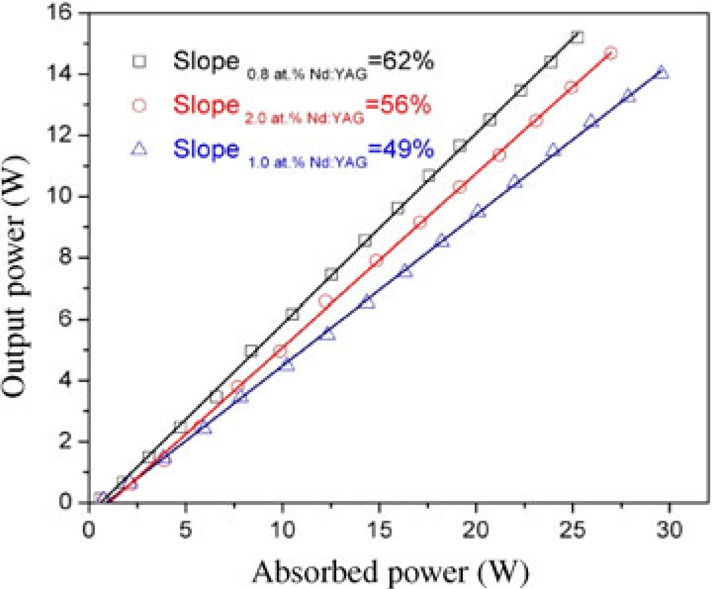
Figure 8. Laser performance of the Nd:YAG ceramic lasers.

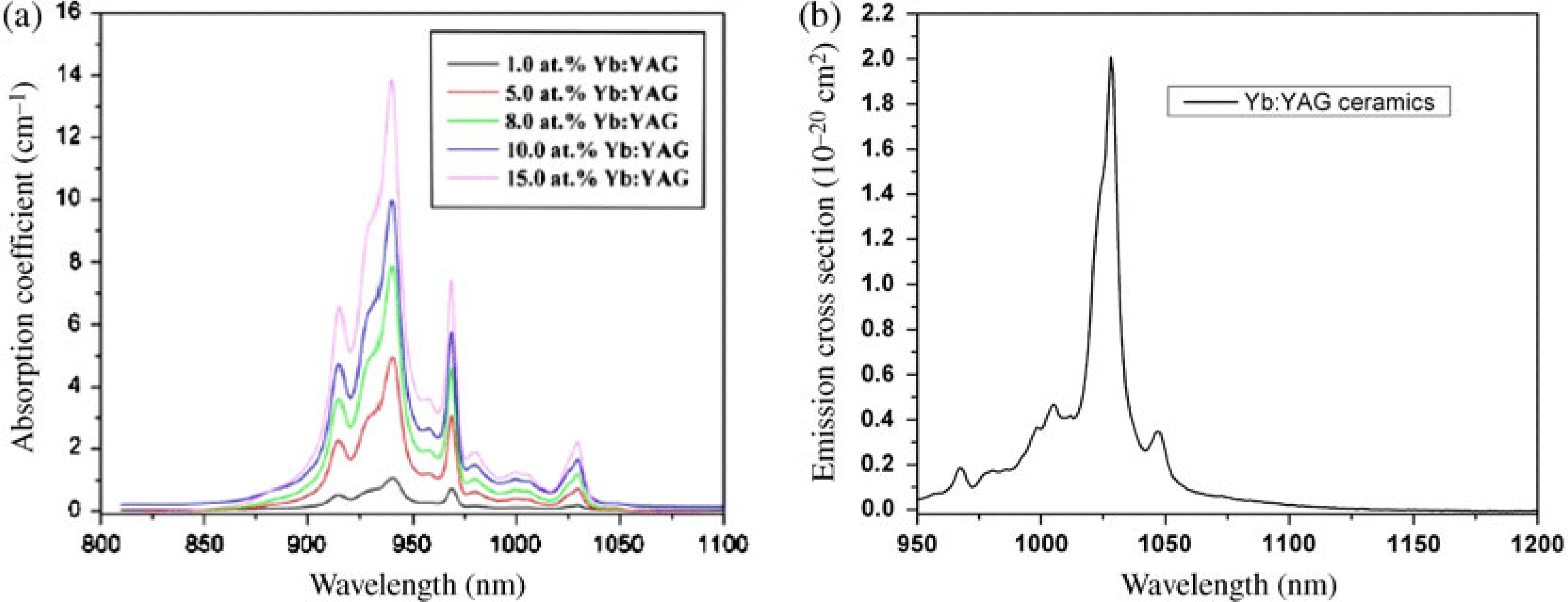
Figure 9. The absorption and emission spectra of the fabricated Yb:YAG ceramics.

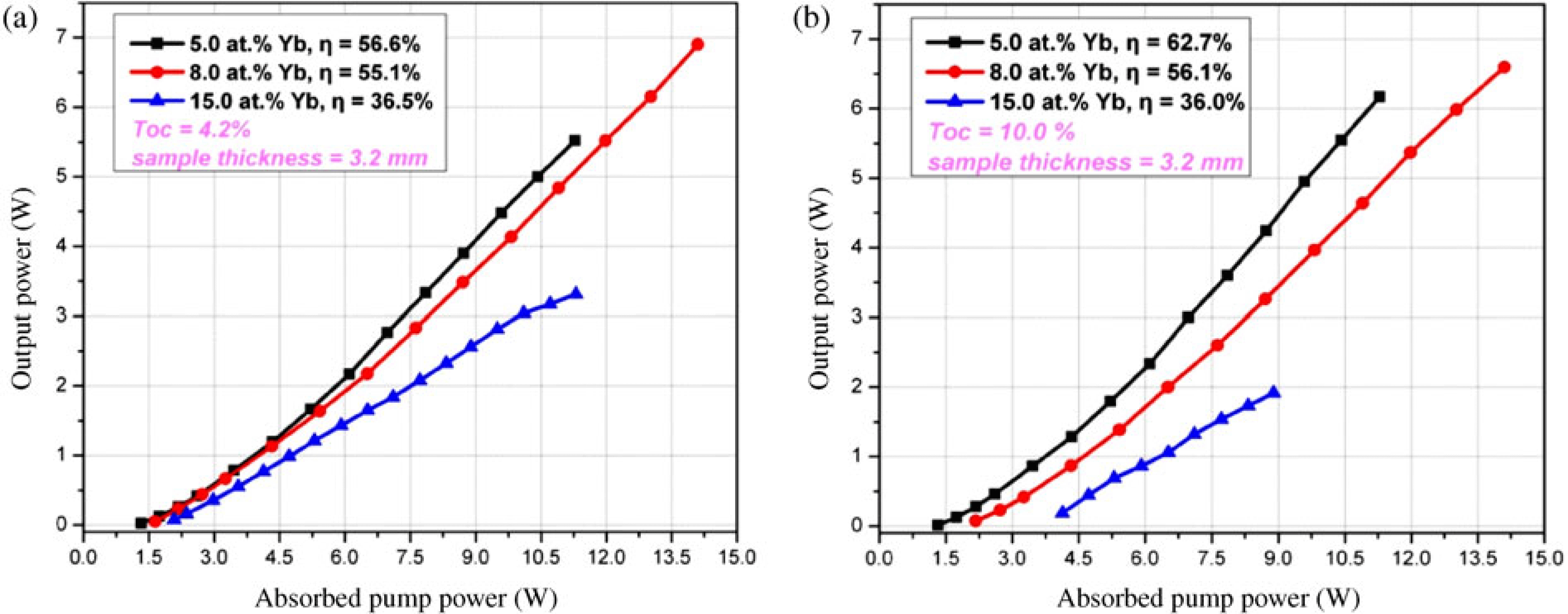
Figure 10. Laser performance of the Yb:YAG ceramic lasers.
4.1.  $1.0\ \mathrm {\mu} {\rm m}$ laser oscillation
Figure 6 shows the absorption and emission spectra of a 1.0 at.% Nd:YAG ceramic fabricated in-house. Compared with those measured with a Nd:YAG single crystal, no measurable difference could be identified. The absorption peak of the ceramic is located at 808 nm, and the peak absorption coefficient is measured as ![]() $8.64\ {\rm cm}^{-1}$, which corresponds to an absorption cross-section of
$8.64\ {\rm cm}^{-1}$, which corresponds to an absorption cross-section of ![]() $6.26\times 10^{-20}\ {\rm cm}^{2}$. From 900 to 1200 nm, there are two main emission bands centered at 946 and 1064 nm, which correspond to the
$6.26\times 10^{-20}\ {\rm cm}^{2}$. From 900 to 1200 nm, there are two main emission bands centered at 946 and 1064 nm, which correspond to the ![]() ${}^{4}\mathrm{F}_{3/2}\to {}^{4}\mathrm{I}_{9/2}$ and
${}^{4}\mathrm{F}_{3/2}\to {}^{4}\mathrm{I}_{9/2}$ and ![]() ${}^{4}\mathrm{F}_{3/2}\to {}^{4}\mathrm{I}_{11/2}$ transitions of the
${}^{4}\mathrm{F}_{3/2}\to {}^{4}\mathrm{I}_{11/2}$ transitions of the ![]() ${\rm Nd}^{3+}$ ions, respectively. The strongest emission peak is at 1064 nm, which is same as that of Nd:YAG single crystals. Figure 7 shows a schematic of our diode-pumped Nd:YAG ceramic laser setup. The Nd:YAG ceramics were cut into pieces of dimension
${\rm Nd}^{3+}$ ions, respectively. The strongest emission peak is at 1064 nm, which is same as that of Nd:YAG single crystals. Figure 7 shows a schematic of our diode-pumped Nd:YAG ceramic laser setup. The Nd:YAG ceramics were cut into pieces of dimension ![]() $3 \times 3 \times 5\ {\rm mm}^{3}$. Nd:YAG ceramics with three
$3 \times 3 \times 5\ {\rm mm}^{3}$. Nd:YAG ceramics with three ![]() ${\rm Nd}^{3+}$ doping concentrations (0.8 at.%, 1.0 at.%, and 2.0 at.%) were used. The laser performance of the Nd:YAG ceramics is shown in Figure 8. The best performance was achieved with the 0.8 at.% Nd:YAG ceramic. A maximum output power of 15.2 W at 1064 nm was obtained under an absorbed pump power of 25 W. The slope efficiency is 62%, which is very close to that of Nd:YAG single crystals.
${\rm Nd}^{3+}$ doping concentrations (0.8 at.%, 1.0 at.%, and 2.0 at.%) were used. The laser performance of the Nd:YAG ceramics is shown in Figure 8. The best performance was achieved with the 0.8 at.% Nd:YAG ceramic. A maximum output power of 15.2 W at 1064 nm was obtained under an absorbed pump power of 25 W. The slope efficiency is 62%, which is very close to that of Nd:YAG single crystals.

Figure 11. The absorption and emission spectra of the fabricated Yb:LuAG ceramics.
The absorption spectra of the fabricated Yb:YAG ceramics under different ![]() ${\rm Yb}^{3+}$ doping concentrations are plotted in Figure 9(a). All the samples have a very strong absorption peak located at 940 nm and two moderate absorption peaks located at 915 and 969 nm, respectively, corresponding to the
${\rm Yb}^{3+}$ doping concentrations are plotted in Figure 9(a). All the samples have a very strong absorption peak located at 940 nm and two moderate absorption peaks located at 915 and 969 nm, respectively, corresponding to the ![]() ${}^{2}\mathrm{F}_{7/2} \to {}^{2}\mathrm{F}_{5/2}$ transition of
${}^{2}\mathrm{F}_{7/2} \to {}^{2}\mathrm{F}_{5/2}$ transition of ![]() ${\rm Yb}^{3+}$. The absorption coefficient at 940 nm increased from
${\rm Yb}^{3+}$. The absorption coefficient at 940 nm increased from ![]() $1.06\ {\rm cm}^{-1}$ under the 1.0 at.%
$1.06\ {\rm cm}^{-1}$ under the 1.0 at.% ![]() ${\rm Yb}^{3+}$ doping concentration to
${\rm Yb}^{3+}$ doping concentration to ![]() $13.87\ {\rm cm}^{-1}$ under the 15.0 at.% doping concentration. Absorption at 1030 nm is clearly observable, which is attributed to the quasi-threelevel nature of the Yb doped gain media. Figure 9(b) shows the emission cross-section of the Yb:YAG ceramics. The peak is at 1028 nm, and it has a value of
$13.87\ {\rm cm}^{-1}$ under the 15.0 at.% doping concentration. Absorption at 1030 nm is clearly observable, which is attributed to the quasi-threelevel nature of the Yb doped gain media. Figure 9(b) shows the emission cross-section of the Yb:YAG ceramics. The peak is at 1028 nm, and it has a value of ![]() $2.01 \times 10^{-20}\ {\rm cm}^{2}$. The laser performance of the Yb:YAG ceramics under two different output couplings
$2.01 \times 10^{-20}\ {\rm cm}^{2}$. The laser performance of the Yb:YAG ceramics under two different output couplings ![]() $(T_{oc})$ was experimentally studied. Yb:YAG ceramics with different doping concentrations (5.0 at.%, 8.0 at.%, and 15.0 at.%) were cut into pieces of dimension
$(T_{oc})$ was experimentally studied. Yb:YAG ceramics with different doping concentrations (5.0 at.%, 8.0 at.%, and 15.0 at.%) were cut into pieces of dimension ![]() $3\times 3\times 3.2\ {\rm mm}^{3}$. The CW laser emission was at 1030 nm. Under
$3\times 3\times 3.2\ {\rm mm}^{3}$. The CW laser emission was at 1030 nm. Under ![]() $T_{oc}= 4.2$%, the laser threshold for the 5.0 at.%, 8.0 at.%, and 15.0 at.% Yb:YAG ceramics was 1.31 W, 1.64 W, and 2.08 W, respectively. Under
$T_{oc}= 4.2$%, the laser threshold for the 5.0 at.%, 8.0 at.%, and 15.0 at.% Yb:YAG ceramics was 1.31 W, 1.64 W, and 2.08 W, respectively. Under ![]() $T_{oc }= 10$%, it was 1.3 W, 2.16 W, and 4.21 W, respectively, as shown in Figure 10(a) and (b). Due to the reabsorption of the laser, the output power did not increase linearly with the absorbed pump power, but has the tendency that the larger the absorbed pump power, the higher the slope efficiency. With the experimentally available pump power, a maximum output power of 6.9 W was achieved on the 8.0 at.% sample under
$T_{oc }= 10$%, it was 1.3 W, 2.16 W, and 4.21 W, respectively, as shown in Figure 10(a) and (b). Due to the reabsorption of the laser, the output power did not increase linearly with the absorbed pump power, but has the tendency that the larger the absorbed pump power, the higher the slope efficiency. With the experimentally available pump power, a maximum output power of 6.9 W was achieved on the 8.0 at.% sample under ![]() $T_{oc}= 4.2$%, while the highest slope efficiency of 62.7% was obtained with the 5.0 at.% Yb:YAG ceramic sample under
$T_{oc}= 4.2$%, while the highest slope efficiency of 62.7% was obtained with the 5.0 at.% Yb:YAG ceramic sample under ![]() $T_{oc}= 10$%. No saturation was observed on all the Yb:YAG ceramic lasers. We believe that, with further optimization of the doping concentration and experimental conditions, even higher output power and slope efficiency could be obtained.
$T_{oc}= 10$%. No saturation was observed on all the Yb:YAG ceramic lasers. We believe that, with further optimization of the doping concentration and experimental conditions, even higher output power and slope efficiency could be obtained.
As there is no concentration quenching for the ![]() ${\rm Yb}^{3+}$ doped laser materials, high doping is preferred to achieve high power and high efficiency of
${\rm Yb}^{3+}$ doped laser materials, high doping is preferred to achieve high power and high efficiency of ![]() ${\rm Yb}^{3+}$ doped lasers. However, a problem associated with
${\rm Yb}^{3+}$ doped lasers. However, a problem associated with ![]() ${\rm Yb}^{3+}$ doped YAG is that, as the
${\rm Yb}^{3+}$ doped YAG is that, as the ![]() ${\rm Yb}^{3+}$ doping concentration is increased, the thermal conductivity of the doped YAG drops significantly. To solve the problem, the compound material
${\rm Yb}^{3+}$ doping concentration is increased, the thermal conductivity of the doped YAG drops significantly. To solve the problem, the compound material ![]() ${\rm Lu}_{3}{\rm Al}_{5}{\rm O}_{12}$ was proposed as an alternative to YAG.
${\rm Lu}_{3}{\rm Al}_{5}{\rm O}_{12}$ was proposed as an alternative to YAG. ![]() ${\rm Lu}_{3}{\rm Al}_{5}{\rm O}_{12}$ has high density
${\rm Lu}_{3}{\rm Al}_{5}{\rm O}_{12}$ has high density ![]() $(6.72\ \text {g cm}^{-3})$, high thermal conductivity
$(6.72\ \text {g cm}^{-3})$, high thermal conductivity ![]() $(9.6\ \text {w/m} \cdot \ {\rm K})$, and a cubic structure. Although the thermal conductivity of LuAG is a little bit smaller than that of YAG, its conductivity decreases only slightly under high Yb doping, which is of benefit to high-power laser operation. We have also fabricated high optical quality Yb:LuAG ceramics with different
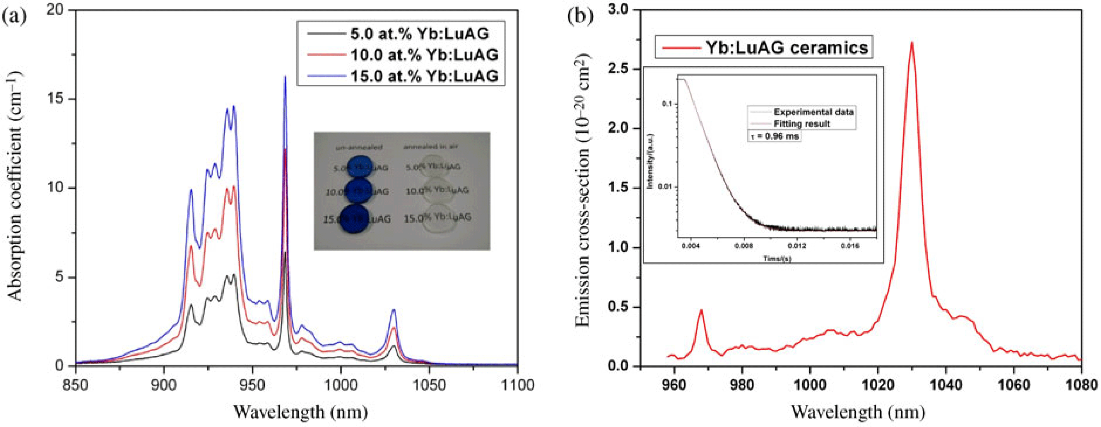
$(9.6\ \text {w/m} \cdot \ {\rm K})$, and a cubic structure. Although the thermal conductivity of LuAG is a little bit smaller than that of YAG, its conductivity decreases only slightly under high Yb doping, which is of benefit to high-power laser operation. We have also fabricated high optical quality Yb:LuAG ceramics with different ![]() ${\rm Yb}^{3+}$ doping concentrations[Reference Xu, Luo and Zhang29]. Figure 11(a) shows the absorption spectra of the as-fabricated Yb:LuAG ceramic samples with different
${\rm Yb}^{3+}$ doping concentrations[Reference Xu, Luo and Zhang29]. Figure 11(a) shows the absorption spectra of the as-fabricated Yb:LuAG ceramic samples with different ![]() ${\rm Yb}^{3+}$ doping concentrations. A photograph of the Yb:LuAG samples is also shown in the inset of the figure. The samples appear blue in color before annealing. After being annealed in air they become colorless and fully transparent. The absorption spectra of the Yb:LuAG ceramics are similar in profile to those of the Yb:YAG ceramics. However the highest absorption peak is located at 968.4 nm. For the samples with 5%, 10%, and 15% at.%
${\rm Yb}^{3+}$ doping concentrations. A photograph of the Yb:LuAG samples is also shown in the inset of the figure. The samples appear blue in color before annealing. After being annealed in air they become colorless and fully transparent. The absorption spectra of the Yb:LuAG ceramics are similar in profile to those of the Yb:YAG ceramics. However the highest absorption peak is located at 968.4 nm. For the samples with 5%, 10%, and 15% at.% ![]() ${\rm Yb}^{3+}$ concentrations, the peak absorption coefficients were measured as
${\rm Yb}^{3+}$ concentrations, the peak absorption coefficients were measured as ![]() $6.4\ {\rm cm}^{-1}, 12.2\ {\rm cm}^{-1}$, and
$6.4\ {\rm cm}^{-1}, 12.2\ {\rm cm}^{-1}$, and ![]() $16.3\ {\rm cm}^{-1}$, respectively. The highest absorption peak of Yb:LuAG is very sharp, with a full width at half maximum (FWHM) of 2.5 nm. The second highest absorption peak is at 940 nm; it is a band consisting of double peaks, centered at 935.6 nm and 939.6 nm, respectively. The two peaks have nearly the same absorption coefficient. The FWHM of the absorption band is 21.6 nm, which favors direct diode pumping with InGaAs laser diodes. The absorption cross-section at the 939 and 968 nm absorption peaks is calculated to be
$16.3\ {\rm cm}^{-1}$, respectively. The highest absorption peak of Yb:LuAG is very sharp, with a full width at half maximum (FWHM) of 2.5 nm. The second highest absorption peak is at 940 nm; it is a band consisting of double peaks, centered at 935.6 nm and 939.6 nm, respectively. The two peaks have nearly the same absorption coefficient. The FWHM of the absorption band is 21.6 nm, which favors direct diode pumping with InGaAs laser diodes. The absorption cross-section at the 939 and 968 nm absorption peaks is calculated to be ![]() $0.73 \times 10^{-20 }\ {\rm cm}^{2}$ and
$0.73 \times 10^{-20 }\ {\rm cm}^{2}$ and ![]() $0.91 \times 10^{-20 }\ {\rm cm}^{2}$, respectively. In addition, there is an absorption peak located at 1030 nm, which is clearly observable on the spectrum. Figure 11(b) shows the emission cross-section and the fluorescent decay curve (inset) for a 5.0 at.% Yb:LuAG ceramic. The emission peak of the Yb:LuAG ceramic is also located at the 1030 nm wavelength, whose emission cross-section is calculated to be
$0.91 \times 10^{-20 }\ {\rm cm}^{2}$, respectively. In addition, there is an absorption peak located at 1030 nm, which is clearly observable on the spectrum. Figure 11(b) shows the emission cross-section and the fluorescent decay curve (inset) for a 5.0 at.% Yb:LuAG ceramic. The emission peak of the Yb:LuAG ceramic is also located at the 1030 nm wavelength, whose emission cross-section is calculated to be ![]() $2.7\times 10^{-20}\ {\rm cm}^{2}$ using the Füchtbauer–Ladenburg (F–L) equation. The value is almost 30% higher than that of Yb:YAG (
$2.7\times 10^{-20}\ {\rm cm}^{2}$ using the Füchtbauer–Ladenburg (F–L) equation. The value is almost 30% higher than that of Yb:YAG (![]() $\sim 2.0 \times 10^{-20}\ {\rm cm}^{2}$). The fluorescence decay of the
$\sim 2.0 \times 10^{-20}\ {\rm cm}^{2}$). The fluorescence decay of the ![]() ${\rm Yb}^{3+}$ ions in the LuAG ceramic sample was measured; the results are shown in the inset of Figure 11(b). A single exponential decay curve was observed. It gives a lifetime of 0.96 ms. The CW laser performance of a 5.0 at.% Yb:LuAG ceramic was experimentally investigated under different output couplings. The Yb:LuAG samples were cut into pieces of dimension
${\rm Yb}^{3+}$ ions in the LuAG ceramic sample was measured; the results are shown in the inset of Figure 11(b). A single exponential decay curve was observed. It gives a lifetime of 0.96 ms. The CW laser performance of a 5.0 at.% Yb:LuAG ceramic was experimentally investigated under different output couplings. The Yb:LuAG samples were cut into pieces of dimension ![]() $3 \times 3 \times 3.2\ {\rm mm}^{3}$. The result is shown in Figure 12. Under
$3 \times 3 \times 3.2\ {\rm mm}^{3}$. The result is shown in Figure 12. Under ![]() $\text {Toc}=50$%, a maximum output power of 7.2 W was obtained at an absorbed pump power of 12.4 W corresponding to a slope efficiency of 65%.
$\text {Toc}=50$%, a maximum output power of 7.2 W was obtained at an absorbed pump power of 12.4 W corresponding to a slope efficiency of 65%.

Figure 12. Laser performance of the Yb:LuAG ceramic lasers.

Figure 13. The absorption and emission spectra of the fabricated Er:YAG ceramics.
4.2.  $1.6\ \mathrm {\mu} {\rm m}$ laser oscillation

Figure 14. A schematic of the Er:YAG ceramic laser setup.

Figure 15. Laser performance of the Er:YAG ceramic laser.
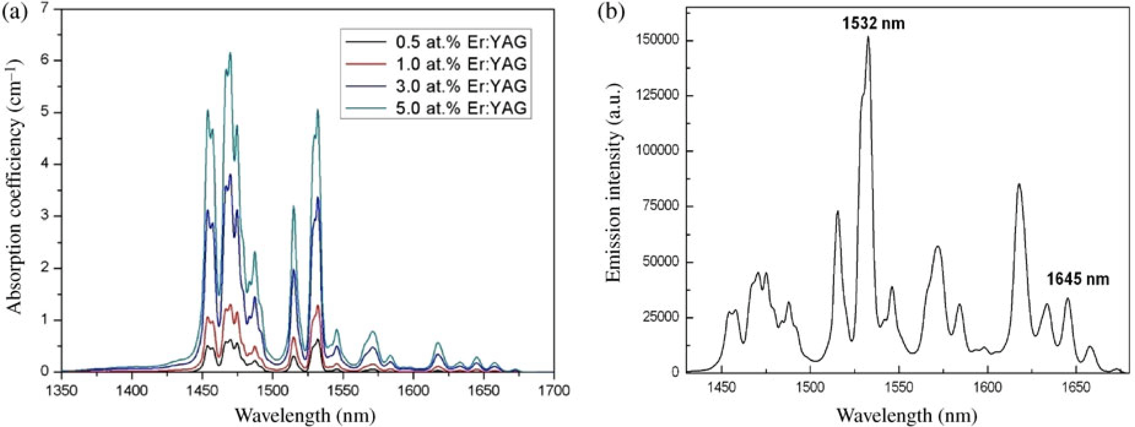
The laser performance of the ![]() ${\rm Er}^{3+}$ doped YAG ceramics was also experimentally investigated. Figure 13(a) shows the absorption spectra of the Er:YAG ceramics under different doping concentrations[Reference Qin, Yang and Zhou25]. The absorption coefficient of the Er:YAG ceramics increased with the increase of the
${\rm Er}^{3+}$ doped YAG ceramics was also experimentally investigated. Figure 13(a) shows the absorption spectra of the Er:YAG ceramics under different doping concentrations[Reference Qin, Yang and Zhou25]. The absorption coefficient of the Er:YAG ceramics increased with the increase of the ![]() ${\rm Er}^{3+}$ concentration. At 1532 nm, the absorption coefficient increased from 0.64 to
${\rm Er}^{3+}$ concentration. At 1532 nm, the absorption coefficient increased from 0.64 to ![]() $5.06\ {\rm cm}^{-1}$ as the
$5.06\ {\rm cm}^{-1}$ as the ![]() ${\rm Er}^{3+}$ concentration increased from 0.5 at.% to 5.0 at.%. Figure 13(b) shows the emission spectrum of the Er:YAG ceramic with a doping concentration of 0.5 at.% in the range 1400–1700 nm. The emission is due to the
${\rm Er}^{3+}$ concentration increased from 0.5 at.% to 5.0 at.%. Figure 13(b) shows the emission spectrum of the Er:YAG ceramic with a doping concentration of 0.5 at.% in the range 1400–1700 nm. The emission is due to the ![]() ${}^{4}{\rm I}_{13/2}\to {}^{4}{\rm I}_{15/2}$ transition of the
${}^{4}{\rm I}_{13/2}\to {}^{4}{\rm I}_{15/2}$ transition of the ![]() ${\rm Er}^{3+}$ ions. The highest emission peak is at 1532 nm, with an emission cross-section of
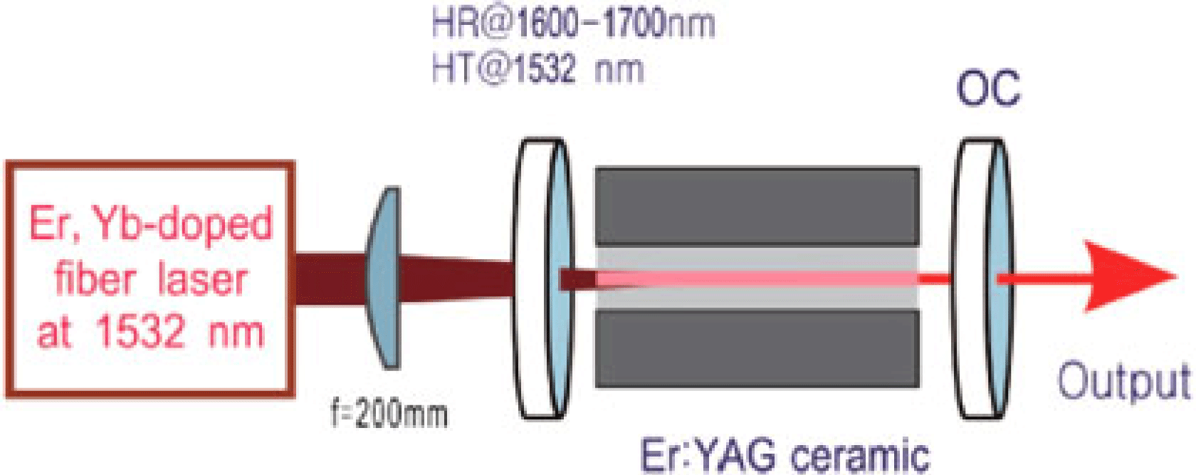
${\rm Er}^{3+}$ ions. The highest emission peak is at 1532 nm, with an emission cross-section of ![]() $0.99 \times 10^{-20 }\ {\rm cm}^{2}$. Figure 14 shows the schematic of the Er:YAG ceramic laser setup used in our experiment. The laser is in-band pumped by an Er–Yb fiber laser at 1532 nm. A 1.0 at.% Er:YAG ceramic sample, cut into pieces of dimension
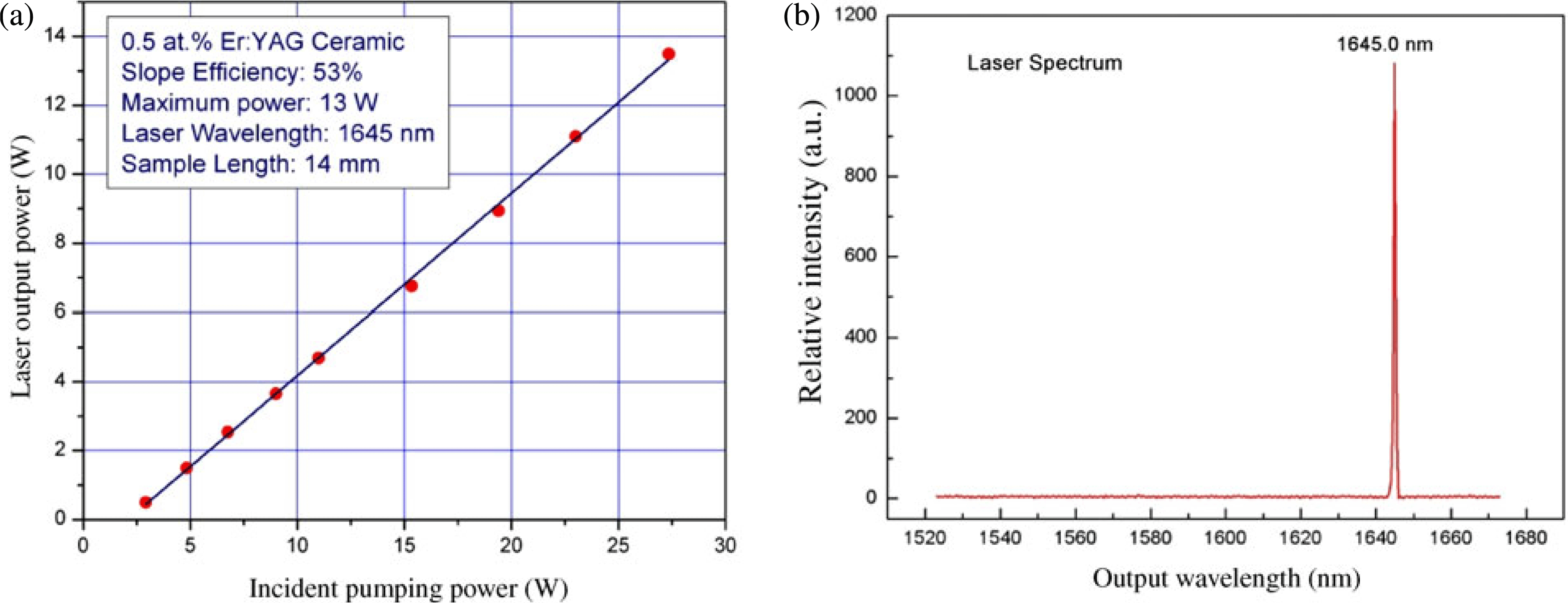
$0.99 \times 10^{-20 }\ {\rm cm}^{2}$. Figure 14 shows the schematic of the Er:YAG ceramic laser setup used in our experiment. The laser is in-band pumped by an Er–Yb fiber laser at 1532 nm. A 1.0 at.% Er:YAG ceramic sample, cut into pieces of dimension ![]() $2 \times 4 \times 14\ {\rm mm}^{3}$, was used as the gain medium. An output coupler with 10% transmission at 1645 nm was used. The performance of the Er:YAG laser is shown in Figure 15. The laser has a pump threshold of
$2 \times 4 \times 14\ {\rm mm}^{3}$, was used as the gain medium. An output coupler with 10% transmission at 1645 nm was used. The performance of the Er:YAG laser is shown in Figure 15. The laser has a pump threshold of ![]() $\sim $1.3 W. It reached an output power of 13.8 W at 1645 nm under 27.3 W of incident pump power. A slope efficiency with respect to the incident pump power of 54.5% and an optical–optical conversion efficiency of 50.5% were achieved. No power saturation was observed on the maximum available pump power, suggesting that further power scaling of the laser is possible by simply increasing the input pumping power.
$\sim $1.3 W. It reached an output power of 13.8 W at 1645 nm under 27.3 W of incident pump power. A slope efficiency with respect to the incident pump power of 54.5% and an optical–optical conversion efficiency of 50.5% were achieved. No power saturation was observed on the maximum available pump power, suggesting that further power scaling of the laser is possible by simply increasing the input pumping power.

Figure 16. The absorption and emission spectra of the fabricated Ho:YAG ceramics.
4.3.  $2.0\ \mathrm {\mu} {\rm m}$ laser oscillation

Figure 17. A schematic of the Ho:YAG ceramics laser setup.

Figure 18. Laser performance of the Ho:YAG ceramic laser.
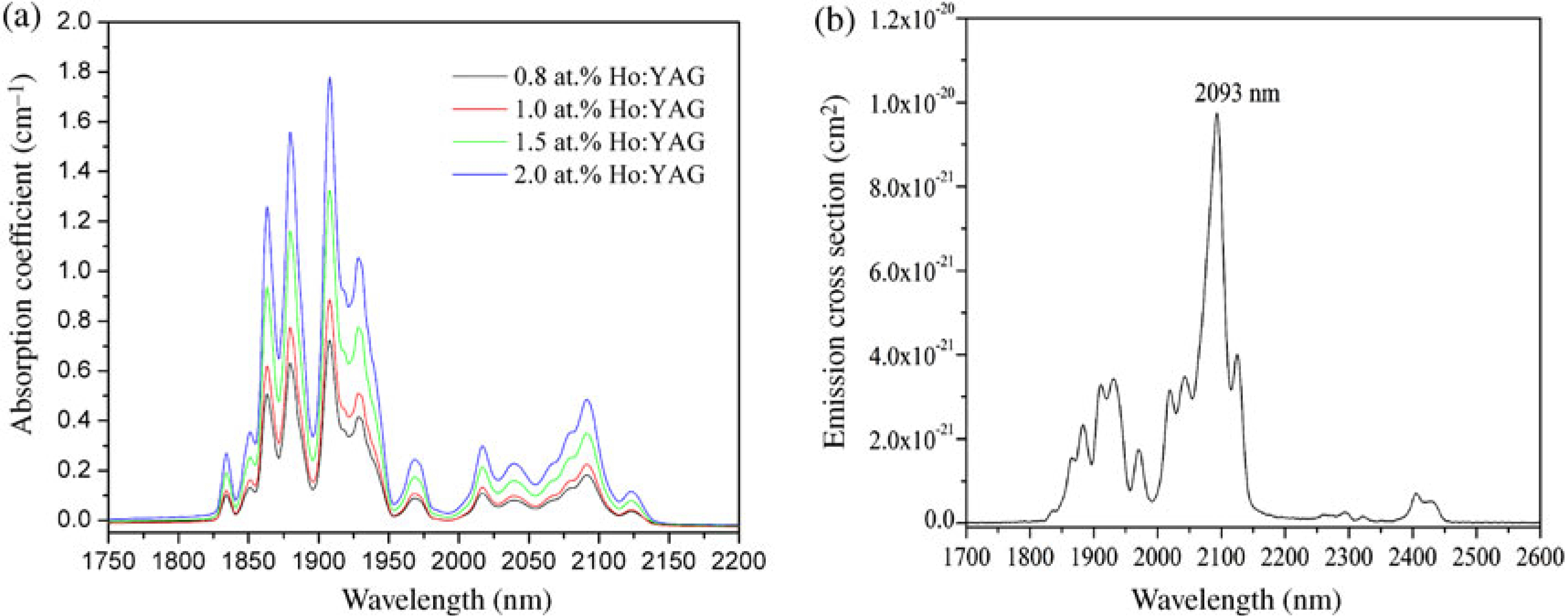
Figure 16 shows the absorption and emission spectra of the Ho:YAG ceramics fabricated in-house[Reference Dong, Xu and Ma18]. As shown, the strongest absorption peak is at 1907 nm, which is the same as that measured with the Ho:YAG single crystals. As the ![]() ${\rm Ho}^{3+}$ doping concentration increased from 0.8 to 2.0 at.%, the absorption coefficient at 1907 nm increased linearly from 0.72 to
${\rm Ho}^{3+}$ doping concentration increased from 0.8 to 2.0 at.%, the absorption coefficient at 1907 nm increased linearly from 0.72 to ![]() $1.78\ {\rm cm}^{-1}$. Based on the measured absorption coefficients, the absorption cross-section of the Ho:YAG ceramic is calculated as
$1.78\ {\rm cm}^{-1}$. Based on the measured absorption coefficients, the absorption cross-section of the Ho:YAG ceramic is calculated as ![]() $0.645 \times 10^{-20}\ {\rm cm}^{2}$. The emission spectrum from 1700 to 2600 nm of a 1.0 at.% Ho:YAG ceramic measured at room temperature is shown in Figure 16(b). The main emission band is centered at 2093 nm, which corresponds to the
$0.645 \times 10^{-20}\ {\rm cm}^{2}$. The emission spectrum from 1700 to 2600 nm of a 1.0 at.% Ho:YAG ceramic measured at room temperature is shown in Figure 16(b). The main emission band is centered at 2093 nm, which corresponds to the ![]() ${}^{5}{\rm I}_7\to {}^{5}{\rm I}_8$ transition of
${}^{5}{\rm I}_7\to {}^{5}{\rm I}_8$ transition of ![]() ${\rm Ho}^{3+}$. The emission cross-section at 2093 nm is calculated to be
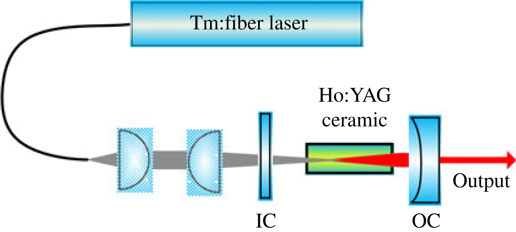
${\rm Ho}^{3+}$. The emission cross-section at 2093 nm is calculated to be ![]() $0.97 \times 10^{-20 }\ {\rm cm}^{2}$ by using the F–L equation. Figure 17 shows a schematic of the Ho:YAG ceramic laser experimentally used. The Ho:YAG ceramic laser is in-band pumped by a home-made Tm:YAG fiber laser at 1907 nm. The dimensions of the Ho:YAG ceramic used were
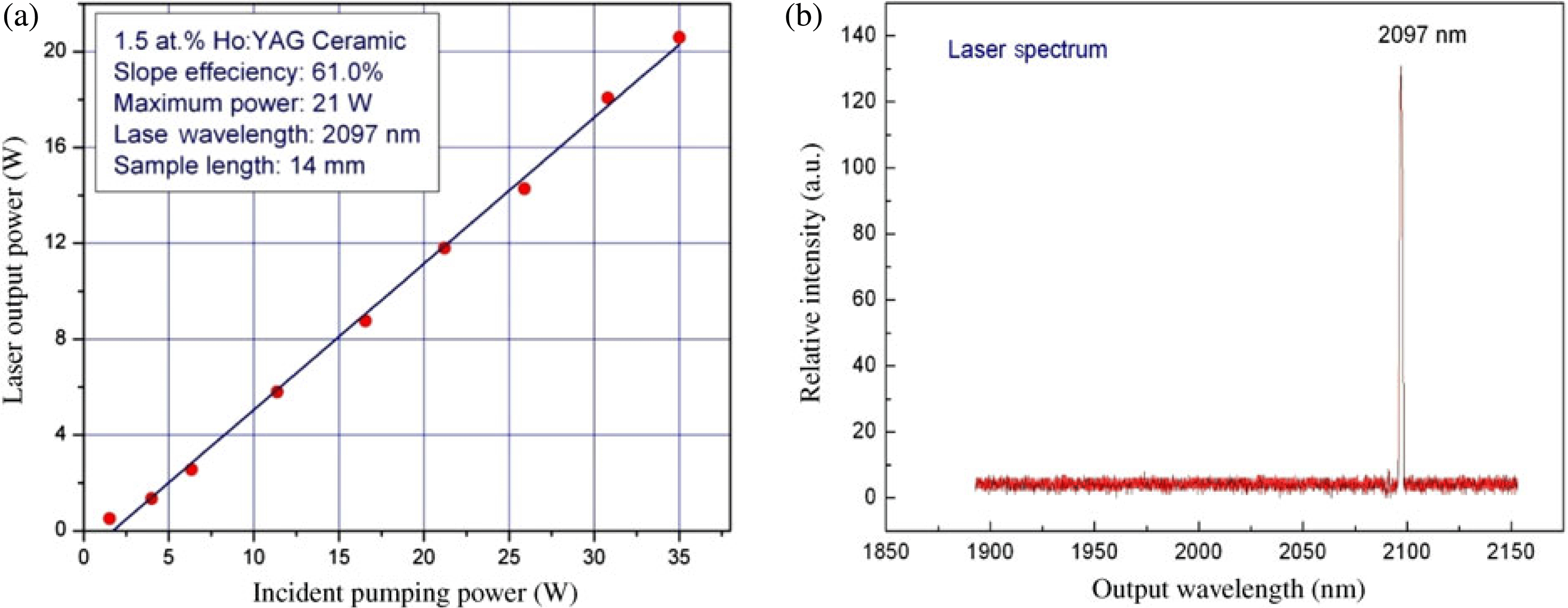
$0.97 \times 10^{-20 }\ {\rm cm}^{2}$ by using the F–L equation. Figure 17 shows a schematic of the Ho:YAG ceramic laser experimentally used. The Ho:YAG ceramic laser is in-band pumped by a home-made Tm:YAG fiber laser at 1907 nm. The dimensions of the Ho:YAG ceramic used were ![]() $2\ {\rm mm} \times 3\ {\rm mm} \times 14\ {\rm mm}$. A 1.5 at.% Ho:YAG ceramic was used as the laser gain medium. With 35 W incident pump power, a maximum output power of 20.6 W at 2097 nm was obtained, corresponding to a slope efficiency of 60.9% and an optical-to-optical conversion efficiency of 58.8%, as shown in figure 18.
$2\ {\rm mm} \times 3\ {\rm mm} \times 14\ {\rm mm}$. A 1.5 at.% Ho:YAG ceramic was used as the laser gain medium. With 35 W incident pump power, a maximum output power of 20.6 W at 2097 nm was obtained, corresponding to a slope efficiency of 60.9% and an optical-to-optical conversion efficiency of 58.8%, as shown in figure 18.
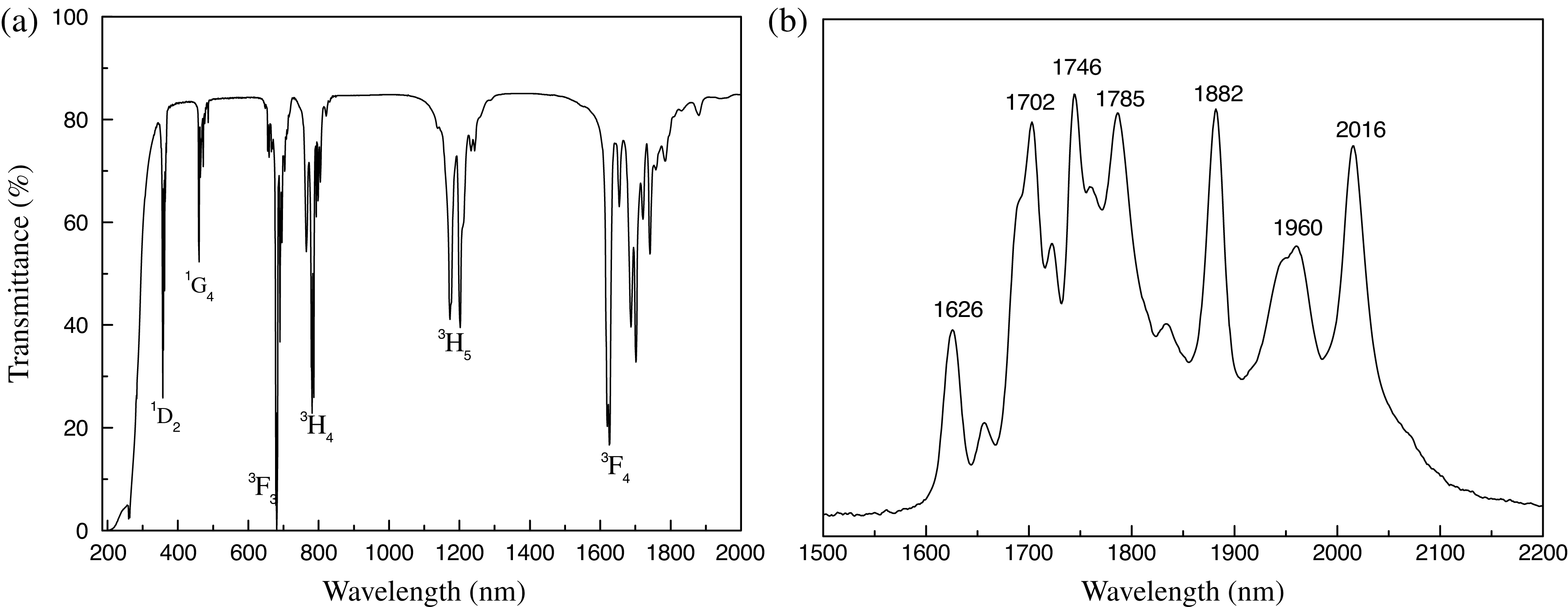
Besides Ho:YAG ceramics, Tm:YAG ceramics also emit in the ![]() $2\ \mathrm {\mu} {\rm m}$ wavelength regime. Figure 19 shows the transmittance and emission spectrum of the in-house fabricated Tm:YAG ceramics. There are six strong absorption bands centered at 356, 458, 684, 781, 1202, and 1626 nm, which correspond to the transitions of
$2\ \mathrm {\mu} {\rm m}$ wavelength regime. Figure 19 shows the transmittance and emission spectrum of the in-house fabricated Tm:YAG ceramics. There are six strong absorption bands centered at 356, 458, 684, 781, 1202, and 1626 nm, which correspond to the transitions of ![]() ${\rm Tm}^{3+}$ from the ground state
${\rm Tm}^{3+}$ from the ground state ![]() ${}^{3}{\rm H}_6$ to its excited state,
${}^{3}{\rm H}_6$ to its excited state, ![]() ${}^{1}{\rm D}_2, {}^{1}{\rm G}_4, {}^{3}{\rm F}_3, {}^{3}{\rm H}_4, {}^{3}{\rm H}_5$, and
${}^{1}{\rm D}_2, {}^{1}{\rm G}_4, {}^{3}{\rm F}_3, {}^{3}{\rm H}_4, {}^{3}{\rm H}_5$, and ![]() ${}^{3}{\rm F}_4$, respectively. The strong emission peaks are at wavelengths of 1626 nm, 1702 nm, 1746 nm, 1785 nm, 1882 nm, 1960 nm, and 2016 nm, respectively. Tm:YAG is a quasithree-level system. Hence, laser emission with wavelength below
${}^{3}{\rm F}_4$, respectively. The strong emission peaks are at wavelengths of 1626 nm, 1702 nm, 1746 nm, 1785 nm, 1882 nm, 1960 nm, and 2016 nm, respectively. Tm:YAG is a quasithree-level system. Hence, laser emission with wavelength below ![]() $1.9\ \mathrm {\mu} {\rm m}$ is difficult to achieve, due to the reabsorption by the
$1.9\ \mathrm {\mu} {\rm m}$ is difficult to achieve, due to the reabsorption by the ![]() ${\rm Tm}^{3+}$ ions.
${\rm Tm}^{3+}$ ions.

Figure 19. The transmittance and emission spectra of a fabricated Tm:YAG ceramic.
Table 1. Summary of the results of the ceramic laser experiments


Figure 20. A schematic of the diode-pumped Tm:YAG ceramic laser setup.

Figure 21. Laser performance of the Tm:YAG ceramic lasers.
Tm:YAG lasers can be directly pumped by commercially available high-power GaAlAs diodes at ![]() $\sim $800 nm (the
$\sim $800 nm (the ![]() ${}^{3}{\rm H}_6 \to {}^{3}{\rm H}_4$ transition). Benefitting from a fortuitous ‘two-for-one’ cross-relaxation process, pumping quantum efficiencies approaching 2 could be achieved with pumping under high
${}^{3}{\rm H}_6 \to {}^{3}{\rm H}_4$ transition). Benefitting from a fortuitous ‘two-for-one’ cross-relaxation process, pumping quantum efficiencies approaching 2 could be achieved with pumping under high ![]() ${\rm Tm}^{3+}$ doping concentrations. Figure 20 shows the schematic of the diode-pumped Tm:YAG ceramic laser used to study the lasing performance of the fabricated Tm:YAG ceramics. The diode laser is operating at 786 nm. Tm:YAG ceramics with different doping concentrations were cut into pieces of dimension
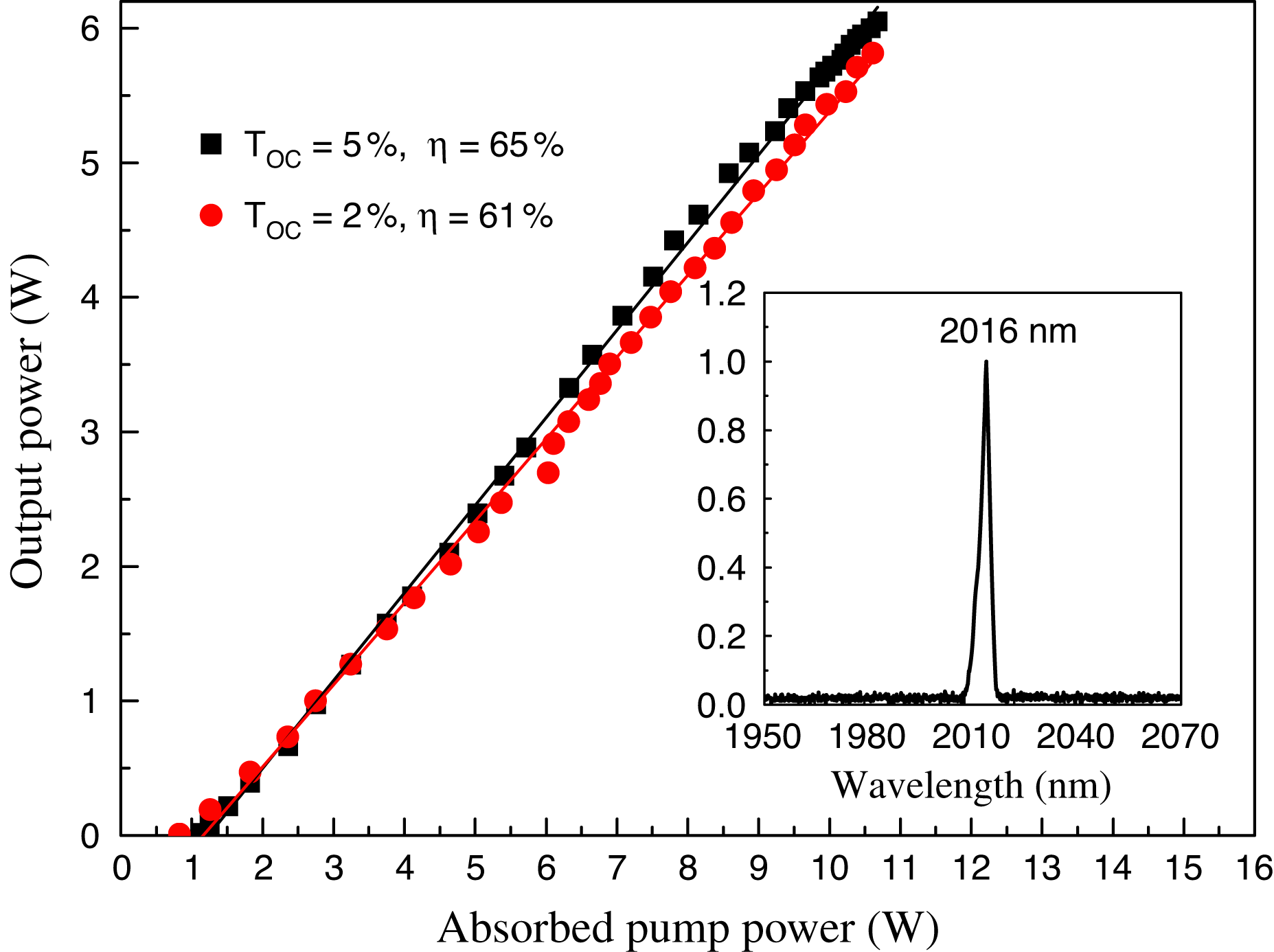
${\rm Tm}^{3+}$ doping concentrations. Figure 20 shows the schematic of the diode-pumped Tm:YAG ceramic laser used to study the lasing performance of the fabricated Tm:YAG ceramics. The diode laser is operating at 786 nm. Tm:YAG ceramics with different doping concentrations were cut into pieces of dimension ![]() $3 \times 3 \times 3.2\ \mathrm{mm}^{3}$. The laser emitted at 2016 nm. With an output coupler of 5% coupling, a maximum output power of 6.05 W was obtained under an absorbed pump power of 10.68 W, giving a slope efficiency of 65%.
$3 \times 3 \times 3.2\ \mathrm{mm}^{3}$. The laser emitted at 2016 nm. With an output coupler of 5% coupling, a maximum output power of 6.05 W was obtained under an absorbed pump power of 10.68 W, giving a slope efficiency of 65%.
In Table 1, we have summarized the laser performance of our fabricated RE:YAG ceramics.
5. Conclusions
High optical quality polycrystalline YAG transparent ceramics doped with various rare-earth ions were successfully fabricated by the reactive sintering method. The laser performance of the fabricated RE:YAG ceramics were studied experimentally. The main results achieved in our works can be summarized as follows.
(1) High-quality RE:YAG transparent ceramics were fabricated using the reactive sintering method under vacuum conditions. Irrespective of the different doped rare-earth ions and their doping levels, defect-free microstructures were observed for all the samples produced.
(2) Highly efficient CW laser oscillations in the ![]() $1.0\ \mathrm {\mu} {\rm m}$ regime were obtained in the Nd:YAG and Yb:YAG ceramics. The highest slope efficiency achieved on the Nd:YAG ceramics is 62%, which is very close to that of Nd:YAG single crystal.
$1.0\ \mathrm {\mu} {\rm m}$ regime were obtained in the Nd:YAG and Yb:YAG ceramics. The highest slope efficiency achieved on the Nd:YAG ceramics is 62%, which is very close to that of Nd:YAG single crystal.
(3) Er:YAG ceramic is suitable for achieving ![]() $\sim 1.6\ \mathrm {\mu} {\rm m}$ laser emission. When end pumped by an Er,Yb-fiber laser at 1532 nm, a maximum output power of 13.8 W at 1645 nm was obtained with a slope efficiency of 54.5%.
$\sim 1.6\ \mathrm {\mu} {\rm m}$ laser emission. When end pumped by an Er,Yb-fiber laser at 1532 nm, a maximum output power of 13.8 W at 1645 nm was obtained with a slope efficiency of 54.5%.
(4) By using a 1.5 at.% Ho:YAG ceramic as the laser medium, 20.6 W laser output at 2097 nm was achieved under 35 W of incident pump power, and a slope efficiency of 61% has been achieved.
(5) High optical quality Tm:YAG laser ceramics have been fabricated. Pumped by a laser diode at 768 nm, highefficiency CW laser operation has been demonstrated.
Acknowledgements
This project is supported by the Priority Academic Program Development of Jiangsu Higher Education Institutions (PAPD) and the National Research Foundation of Singapore under contract NRF-G-CRP-2007-01.


