1 Introduction
Preplasma has an important effect on the interaction between laser and matter, especially in solid targets, which produces different laser absorption mechanisms in sub-relativistic laser states, such as resonance absorption[ Reference Friedberg, Mitchell, Morse and Rudsinski 1 ] and vacuum heating (the Brunel mechanism)[ Reference Brunel 2 ]. Based on these studies, several interesting results have been obtained recently, such as the Brunel-like mechanism[ Reference Geindre, Marjoribanks and Audebert 3 ], high harmonic generation[ Reference Bocoum, Thevenet, Bohle, Beaurepaire, Vernier, Jullien, Faure and Lopez-Martens 4 ], and vacuum electron acceleration[ Reference Thévenet, Leblanc, Kahaly, Vincenti, Vernier, Quéré and Faure 5 ]. With the gargantuan laser powers projected to be realized in the developing petawatt (PW) facilities ELI in Europe[ 6 – Reference Mondal, Shirozhan and Ahmed 9 ] and SULF in China[ Reference Chu, Gan and Liang 10 ], the interaction between lasers and plasmas is poised to occur in the ultrarelativistic state[ Reference Brady, Ridgers, Arber, Bell and Kirk 11 ]. As is commonly understood, in the quantum electrodynamics (QED)-dominated regime, when an ultraintense laser interacts with a target, γ-rays can be generated by synchrotron radiation arising from high-energy electrons traveling in a strong, background electromagnetic field[ Reference Ridgers, Brady and Duclous 12 , Reference Zhu, Chen and Weng 13 ]. Previous studies focused on the function of the preplasma before a dense target[ Reference Nakamura, Koga, Esirkepov, Kando, Korn and Bulanov 14 , Reference Lezhnin, Sasorov, Korn and Bulanov 15 ], scanning different parameters to obtain the optimal γ-ray source. The other efficient method to generate γ-ray flare is to make accelerated electrons interact with a reflected laser, a method called all-optical Compton backscattering, in which electrons may be accelerated by a wakefield[ Reference Phuoc, Corde and Thaury 16 , Reference Ong, Seto, Berceanu, Aogaki and Neagu 17 ] or pondermotive force[ Reference Gong, Hu and Lu 18 ] and laser is reflected by a dense plasma mirror. In these cases, underdense gas or nanoparticles[ Reference Huang, Kim and Zhou 19 ] are required before the solid targets in their plans. The γ-rays generated in different regimes have lent themselves to many applications, such as dense matter tomography[ Reference Weeks, Litvinenko and Madey 20 ], photonuclear reactions[ Reference Schreiber, Canon and Crowley 21 ], and laboratory astrophysics[ Reference Bulanov, Esirkepov, Kando, Koga, Kondo and Korn 22 ]. Previous research has shown that an ultraintense laser interacting with a plasma can emit γ-rays in different directions, depending on the plasma density[ Reference Brady, Ridgers, Arber, Bell and Kirk 11 , Reference Ridgers, Brady and Duclous 12 , Reference Chang, Qiao and Zhang 23 ] and the corresponding physical mechanisms at play.
As mentioned previously, the preplasma scale length plays an important role in the ultraintense laser matter interactions, which is the object of the present article. Via two-dimensional (2D) simulation and theoretical analysis, we found that the preplasma affects the γ-ray generation markedly. With increasing preplasma scale length, the angular distribution of the γ-rays tends to proceed with small angle. Moreover, the conversion efficiency of laser to γ-ray reaches its highest at an appropriate scale length. This shows that piled plasma formed in preplasma has similar effects to the reflecting mirror in an all-optical Compton backscattering scenario. The mirror is usually made of a solid target and reflects the laser. We propose a simple 2D analytical model to explain the simulation results, which is in good agreement with our simulation. It indicates that a single solid target with appropriate preplasma could also be robust to generating a γ-ray source.
2 Traditional mechanism of γ-ray production in uniform plasma
The nonlinear QED effect[ Reference Ritus 24 ] must be considered under ultraintense laser conditions, which mainly contains two important processes: γ-ray generation through synchrotron radiation and electron–positron pair creation by the Breit–Wheeler (BW) process[ Reference Ridgers, Kirk and Duclous 25 ]. These two processes can be simply described as
where
![]() ${\mathrm{\gamma}}_{\rm l}$
is a laser photon and
${\mathrm{\gamma}}_{\rm l}$
is a laser photon and
![]() ${\mathrm{\gamma}}_{\rm h}$
is a gamma photon.
${\mathrm{\gamma}}_{\rm h}$
is a gamma photon.
γ-ray generation is controlled by the parameter:
 $\begin{align}\eta =\bigg(\frac{\gamma}{E_{\mathrm{s}}}\bigg)|{E}_{\perp }+\beta \times cB|,\end{align}$
which is the ratio of the electromagnetic field in the electron’s rest frame to the Schwinger field (
![]() ${E}_{\mathrm{s}}=1.3\times {10}^{18}\ \mathrm{V}/\mathrm{m}$
)[
Reference Schwinger
26
], where
${E}_{\mathrm{s}}=1.3\times {10}^{18}\ \mathrm{V}/\mathrm{m}$
)[
Reference Schwinger
26
], where
![]() $\gamma$
is the Lorentz factor of the relativistic electron,
$\gamma$
is the Lorentz factor of the relativistic electron,
![]() ${E}_{\perp }$
is the electric field perpendicular to the direction of motion of the electron, β is the electron velocity normalized by the speed of light c, and B is the magnetic field. When
${E}_{\perp }$
is the electric field perpendicular to the direction of motion of the electron, β is the electron velocity normalized by the speed of light c, and B is the magnetic field. When
![]() $\eta$
approaches unity, the QED process must be considered, especially γ-ray emission.
$\eta$
approaches unity, the QED process must be considered, especially γ-ray emission.
As can be found in the formula, the motion of the electrons and the electromagnetic field they experience determine the production of γ-rays. There are four main mechanisms of γ-ray generation in uniform plasma according to the density (shown in Figure 1), which produce different electron behaviors.
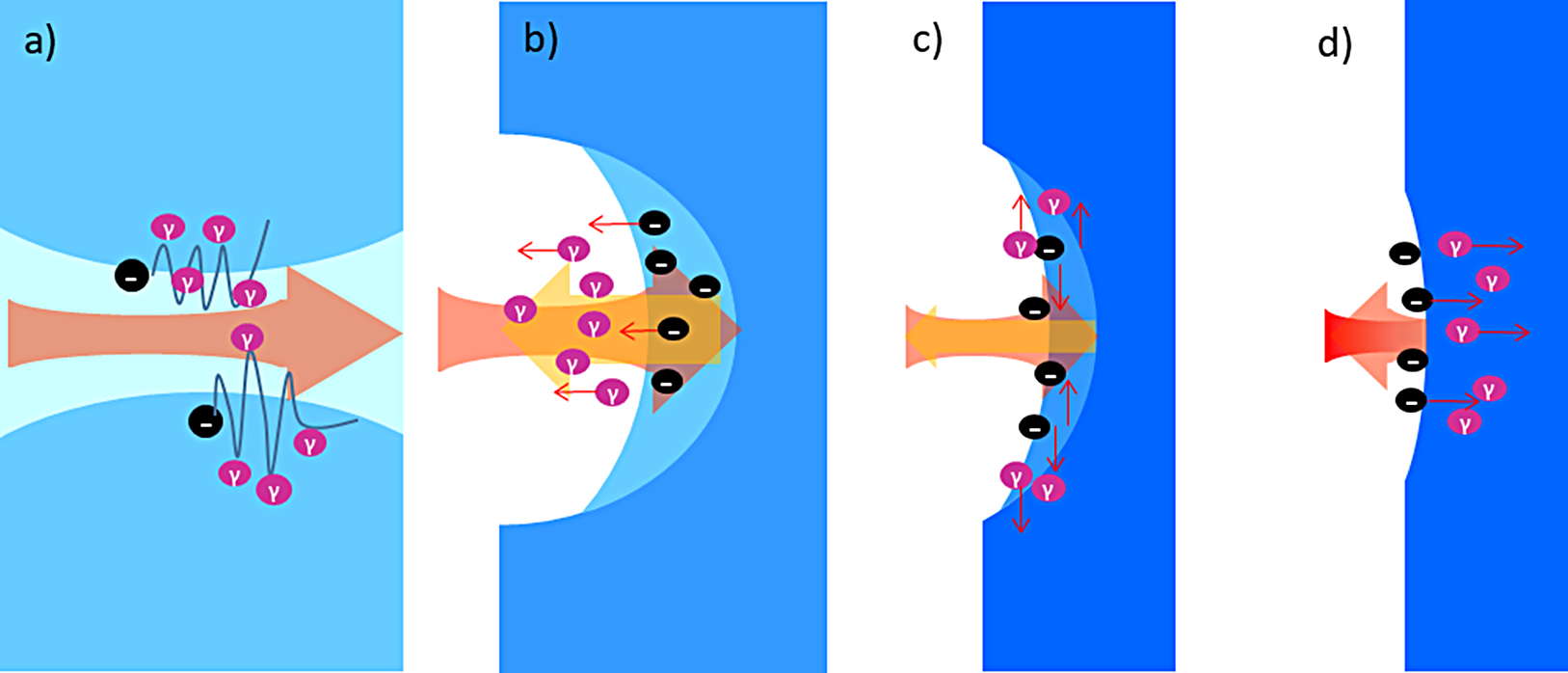
Figure 1 Schematic of traditional γ-ray generation mechanisms at uniform plasma with different density (blue backgrounds represent plasma densities; black circles are electrons; purple represents the gamma photons; small red arrows show the moving direction of the electrons and gamma photons; light red arrows are the laser; and yellow arrows are the space charge force). (a) Low-density plasma n
e
![]() $\,\sim\,$
n
c, forming a plasma channel. (b) Plasma density is close to the penetration threshold value n
e
$\,\sim\,$
n
c, forming a plasma channel. (b) Plasma density is close to the penetration threshold value n
e
![]() $\;\sim\,$
n
th, showing the RESE process. (c) Transition region with n
th
<n
e
<n
c
* of the TOEE mechanism. (d) High density of n
e
>n
c
* of the SDE process.
$\;\sim\,$
n
th, showing the RESE process. (c) Transition region with n
th
<n
e
<n
c
* of the TOEE mechanism. (d) High density of n
e
>n
c
* of the SDE process.
In a comparatively low-density plasma of near-critical density (
 ${n}_{\mathrm{e}}\sim {n}_{\mathrm{c}},\,{n}_{\mathrm{c}}=\frac{\omega_\mathrm{L}^2{\varepsilon}_0{m}_{\mathrm{e}}}{e^2}$
is the critical density), the laser penetrates the plasma and a proportion of the electrons become trapped in the plasma channel owing to the combined effects of the radiation reaction and the self-generated magnetic field[
Reference Chang, Qiao and Huang
27
]. Brilliant forward collimated γ-rays can be generated by relativistic electron bunches through synchrotron radiation, in a cone with an angle 1/
![]() $\gamma$
(
$\gamma$
(
![]() $\gamma$
is the Lorentz factor of the electron) around the direction of electron motion.
$\gamma$
is the Lorentz factor of the electron) around the direction of electron motion.
When the plasma is no longer transparent (the plasma density is close to the penetration threshold value n
e
![]() $\;\sim\,$
n
th, in which n th satisfies
$\;\sim\,$
n
th, in which n th satisfies
 $$\begin{align*}{a}_0^2&=\frac{1}{4}\bigg[2{n}_{\mathrm{th}}(1+{a}_{\rm d}^2)\bigg(\sqrt{1+{a}_{\rm d}^2}-1\bigg)-{a}_{\rm d}^4\bigg] \\[3pt]&\quad \bigg({a}_{\rm d}^2={n}_{\mathrm{th}}\bigg(\frac{9}{8}{n}_{\mathrm{th}}-1+\frac{3}{2}\sqrt{\frac{9}{16}{n}_{\mathrm{th}}^2-{n}_{\mathrm{th}}+1}\bigg)\bigg)\end{align*}$$
for a circularly polarized laser[ Reference Robinson, Trines, Dover and Najmudin 28 ] and more complicated for a linearly polarized laser[ Reference Lefebvre and Bonnaud 29 , Reference Sakagami and Mima 30 ]) so that no stable plasma channel can be formed, a process known as ‘reinjected electron synchrotron emission’ (RESE)[ Reference Brady, Ridgers, Arber, Bell and Kirk 11 ] generates a backward γ-ray beam. The backward reinjected electrons are accelerated by a space-charge field when the ponderomotive force is smaller than charge-separation electrostatic force at the laser pulse back edge. The γ-rays are emitted by the backward reinjected electrons traveling in the incident laser field.
In the transition region with n
th
<n
e
<n
c
* (n
c
* is the relativistically corrected critical density, which depends on the relativistic effect as
![]() ${n}_{\mathrm{c}}^{\ast}\sim \left\langle \gamma \right\rangle {n}_{\mathrm{c}}$
and the energy distribution between the degrees of freedom in the plasma[
Reference Chang, Qiao and Zhang
23
,
Reference Stark, Bhattacharjee, Arefiev, Toncian, Hazeltine and Mahajan
31
]), the longitudinal laser ponderomotive force can come to a balance with the restoring electrostatic force. The electrons mainly oscillate in the transverse direction. Thus, transversely emitted γ-rays at laser frequency are produced by the transversely oscillating electron synchrotron emission (TOEE)[
Reference Brady, Ridgers, Arber, Bell and Kirk
11
].
${n}_{\mathrm{c}}^{\ast}\sim \left\langle \gamma \right\rangle {n}_{\mathrm{c}}$
and the energy distribution between the degrees of freedom in the plasma[
Reference Chang, Qiao and Zhang
23
,
Reference Stark, Bhattacharjee, Arefiev, Toncian, Hazeltine and Mahajan
31
]), the longitudinal laser ponderomotive force can come to a balance with the restoring electrostatic force. The electrons mainly oscillate in the transverse direction. Thus, transversely emitted γ-rays at laser frequency are produced by the transversely oscillating electron synchrotron emission (TOEE)[
Reference Brady, Ridgers, Arber, Bell and Kirk
11
].
When the density is greater than n c *, the laser pulse can only penetrate the target to several skin depths, after which it is reflected backwards. A small number of electrons, accelerated by the ponderomotive force within several skin depths, counterpropagate with the reflected pulse, and emit forward γ-ray bursts, a process known as skin-depth emission (SDE)[ Reference Brady, Ridgers, Arber, Bell and Kirk 11 , Reference Ridgers, Brady and Duclous 12 ].
The four traditional mechanisms mentioned previously occur specifically in a uniform plasma with sharp edge. If a preplasma exists that covers a broad range from underdense to solid density, the γ-ray generation is not simply the superimposition of the four traditional mechanisms. The preplasma will alter the electron acceleration and laser reflection process, which then alters the features of the γ-rays. This represents a new phenomenon, as described in the following.
3 Simulation setup
Here, a 2D particle-in-cell (PIC) simulation code OPIC[ Reference Zhang, Zhang and Hong 32 ] was used to investigate the process of an ultraintense laser (1022 W/cm2) irradiating a solid CH target with different preplasma scale lengths. A QED model is included in the code, which takes into account QED effects of the synchrotron radiation of γ-rays and the Breit–Wheeler electron–positron pair production using a Monte Carlo algorithm. Meanwhile, the radiation reaction effect is also taken into account in our simulation, which is important in the QED regime[ Reference Piazza, Hatsagortsyan and Keitel 33 – Reference Poder, Tamburini and Sarri 36 ]. It presents high-energy electrons that partially lose their energy through emitting gamma photons in laser field.
In the simulation, a box of dimensions 25 m × 10 m (
![]() $x\times y$
) is divided into 2500 grids in the x direction and 1000 in the y direction. A p-polarized laser pulse, with a peak intensity of
$x\times y$
) is divided into 2500 grids in the x direction and 1000 in the y direction. A p-polarized laser pulse, with a peak intensity of
![]() $5.5\times {10}^{22}\ \mathrm{W}/{\mathrm{cm}}^2\left({a}_0=200\right)$
and wavelength of λ = 1 m, propagates from the left boundary. It has a transverse Gaussian profile with a full width at half maximum (FWHM) radius of r = 2λ and a sine square temporal profile a
$5.5\times {10}^{22}\ \mathrm{W}/{\mathrm{cm}}^2\left({a}_0=200\right)$
and wavelength of λ = 1 m, propagates from the left boundary. It has a transverse Gaussian profile with a full width at half maximum (FWHM) radius of r = 2λ and a sine square temporal profile a
![]() $\,={a}_0{\sin}^2\left(\mathrm{\pi} t/20{T}_{\mathrm{L}}\right)$
, in which
$\,={a}_0{\sin}^2\left(\mathrm{\pi} t/20{T}_{\mathrm{L}}\right)$
, in which
![]() ${T}_{\mathrm{L}}$
is the laser period. The target is composed of CH2, which consists of a uniform main target and a preplasma before the main target, as shown in Figure 2. The uniform main target is located from 18λ to 20λ, with an electron density 200n
c (
${T}_{\mathrm{L}}$
is the laser period. The target is composed of CH2, which consists of a uniform main target and a preplasma before the main target, as shown in Figure 2. The uniform main target is located from 18λ to 20λ, with an electron density 200n
c (
![]() ${n}_{\mathrm{c}}={\omega}_{{\rm L}}^2{\varepsilon}_0{m}_{\mathrm{e}}/{e}^2$
is the critical density). The target is fully ionized, and the initial temperatures of ions and electrons are 30 eV and 1 keV, respectively. Each cell of plasma is represented by 50 pseudoelectrons, 25 pseudoprotons, and 16 pseudocarbons. The scale lengths L of the exponential preplasma (
${n}_{\mathrm{c}}={\omega}_{{\rm L}}^2{\varepsilon}_0{m}_{\mathrm{e}}/{e}^2$
is the critical density). The target is fully ionized, and the initial temperatures of ions and electrons are 30 eV and 1 keV, respectively. Each cell of plasma is represented by 50 pseudoelectrons, 25 pseudoprotons, and 16 pseudocarbons. The scale lengths L of the exponential preplasma (
![]() $L={\left(\mathrm{d}\ \ln n/\mathrm{d}x\right)}^{-1}$
) are set to L = 4λ (2–18 m in the x direction), L = 2λ (10–18 m), L = 0.5λ (16–18 m), and L = 0. The cutoff electron density is about 3.6n
c to minimize the computational cost. We also simulated a larger preplasma region, in which the cutoff density of electrons was below n
c. There is no difference between the simulation results for the same scale length parameters, which means that the contribution of electrons to γ-ray generation in the <3.6n
c attenuate plasma region can be ignored.
$L={\left(\mathrm{d}\ \ln n/\mathrm{d}x\right)}^{-1}$
) are set to L = 4λ (2–18 m in the x direction), L = 2λ (10–18 m), L = 0.5λ (16–18 m), and L = 0. The cutoff electron density is about 3.6n
c to minimize the computational cost. We also simulated a larger preplasma region, in which the cutoff density of electrons was below n
c. There is no difference between the simulation results for the same scale length parameters, which means that the contribution of electrons to γ-ray generation in the <3.6n
c attenuate plasma region can be ignored.
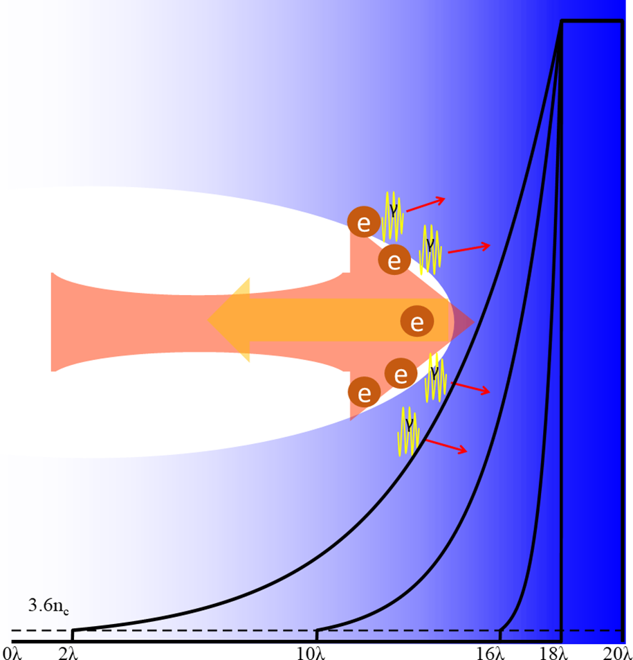
Figure 2 Schematic of the simulation setup and γ-ray generation mechanisms for a solid target with preplasma. Electrons are accelerated in the preplasma, and then interact with the reflected laser through the piled preplasma, emitting bright gamma radiation.
4 Results and discussion
In Figure 3, the temporal evolution of energetic electron numbers with
![]() $\eta >0.05$
is shown at four kinds of preplasma scale lengths. In each case, the electron number first increases, then peaks, and finally decays. The electron number oscillates at twice the laser frequency. With the increasing preplasma scale length, the characteristic times of the maximum electron numbers (close to the peak γ-ray emission) emerge earlier, which are 31.4T (L = 0), 27.9T (L = 0.5λ), 23.9T (L = 2λ), and 20.5T (L = 4λ), respectively. The temporal integrated electron numbers are also amplified by the preplasma. Different characteristic times and energetic electron numbers indicate different mechanisms of γ-ray generation, as discussed in the following.
$\eta >0.05$
is shown at four kinds of preplasma scale lengths. In each case, the electron number first increases, then peaks, and finally decays. The electron number oscillates at twice the laser frequency. With the increasing preplasma scale length, the characteristic times of the maximum electron numbers (close to the peak γ-ray emission) emerge earlier, which are 31.4T (L = 0), 27.9T (L = 0.5λ), 23.9T (L = 2λ), and 20.5T (L = 4λ), respectively. The temporal integrated electron numbers are also amplified by the preplasma. Different characteristic times and energetic electron numbers indicate different mechanisms of γ-ray generation, as discussed in the following.
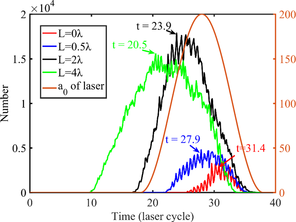
Figure 3 Temporal evolution of electron numbers with
![]() $\eta >0.05$
at preplasma scale length of 0, 0.5λ, 2λ, and 4λ (the characteristic times of the maximum electron numbers are marked with arrows). The laser pulse profile at x = 18λ is also provided for the case of L = 0.
$\eta >0.05$
at preplasma scale length of 0, 0.5λ, 2λ, and 4λ (the characteristic times of the maximum electron numbers are marked with arrows). The laser pulse profile at x = 18λ is also provided for the case of L = 0.
Figure 4 provides the spatial distribution of electrons and gamma photons, and the phase space distribution of electron momentum at characteristic times with various preplasma scale lengths. Figure 5 shows the corresponding angular distributions of electrons and gamma photons at the same time.

Figure 4 (a)–(d) Spatial density distributions of the electrons (black) and gamma photons (red) at corresponding characteristic times. (e)–(l) Phase space distribution of electron momentum (e)–(h) Px and (i)–(l) Py at the characteristic time. There are four cases: (a), (e), (i) L = 0; (b), (f), (j) L = 0.5λ (preplasma region 16–18 µm); (c), (g), (k) L = 2λ (10–18 µm); (d), (h), (l) L = 4λ (2–18 µm). The colorbars represent the electron density.
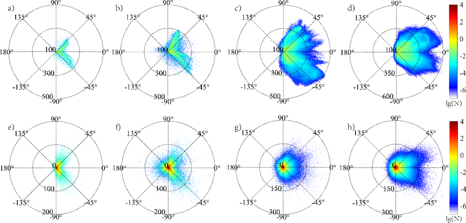
Figure 5 The angular energy distributions
![]() $\lg [N\left(\theta, \varepsilon \right)]$
of (a)–(d) energetic electrons and (e)–(h) and gamma photons at corresponding characteristic times (all units are MeV): (a), (e) L = 0; (b), (f) L = 0.5λ; (c), (g) L = 2λ; (d), (h) L = 4λ. The colorbars represent the lg N of electrons or gamma photons (N represents their density).
$\lg [N\left(\theta, \varepsilon \right)]$
of (a)–(d) energetic electrons and (e)–(h) and gamma photons at corresponding characteristic times (all units are MeV): (a), (e) L = 0; (b), (f) L = 0.5λ; (c), (g) L = 2λ; (d), (h) L = 4λ. The colorbars represent the lg N of electrons or gamma photons (N represents their density).
The sharpest boundary case of L = 0 presents typical characteristics of the SDE mechanism. The gamma ray and energetic electrons are generated in laser skin layer from the region of x>18λ, which is the dense plasma of 200nc , seen in Figure 4(a). The energetic electron have similar forward and transverse momentum (as shown in Figures 4(e) and 4(i)), which makes the electrons and gamma photons split into two large angles around ±45° in the forward direction, as shown in Figures 5(a) and 5(e).
When increasing the preplasma scale length slightly to L = 0.5λ, the energetic electrons are born from two different regions: dense plasma of 200n c (x > 18λ) and preplasma <200n c (x < 18λ), marked by a red dashed line in Figure 4(b). Most energetic electrons are produced in dense plasma of 200n c via an SDE-like mechanism. In addition to those accelerated in skin depth similar to SDE, electrons are also accelerated in preplasma. Therefore, the forward-moving electrons have higher momentum and numbers owing to the longer acceleration length, as shown in Figures 4(f) and 4(j). The forward-moving energetic electrons interact with the backward laser field reflected by the skin layer of dense plasma, and produce brighter forward γ-rays. Some energetic electrons are generated in preplasma of x < 18λ, which exhibit obvious features of the RESE mechanism. The electrons have backward and transverse momentum. The backward reinjected electrons, reflected by the space-charge field of dense plasma, counterpropagate in the incident laser field, and emit a burst of backward γ-rays in preplasma, as can be seen in Figure 5(f). Thus, the angular profiles of energetic electrons and γ-rays present two forward ±45° peaks (SDE-like) and one backward peak (RESE), as shown in Figures 5(b) and 5(f).
If further increasing the preplasma to L = 2λ scale length, the generation region of γ-rays has changed apparently: the majority of γ-rays generated in underdense preplasma below
![]() $\sim 74{n}_{\mathrm{c}}$
(x < 16λ) and the minority in dense preplasma of 74n
c–200n
c (16λ < x < 18λ), which is illustrated in Figure 4(c) and Figure 6(a). The behaviors of electrons in those two regions are significantly different as presented in Figures 4(g) and 4(f). In underdense preplasma (<74n
c), electrons are mainly going forward accompanied by transverse oscillation, which emit a forward γ-ray beam. However, in the dense preplasma region of 74n
c–200n
c, electrons only oscillate in transverse direction with little forward motion, which generates the typical transverse γ-ray emission of the TOEE mechanism. Therefore, the angular distribution of γ-rays is the superposition of the dominated forward γ-rays in the underdense region and transverse γ-ray emission by TOEE in dense plasma, as shown in Figures 5(c) and 5(g). As can be found in Figure 6, the piled plasma by laser ponderomotive force produces a dense plasma mirror in preplasma, which plays the same function as an additional plasma mirror[
Reference Huang, Kim and Zhou
37
] in double target scheme. The backward laser field is mainly reflected by the preplasma region instead of the main target because there is no laser field behind the piled plasma. Meanwhile, the piled electron density shown in Figure 6(b) is almost reaches 200
$\sim 74{n}_{\mathrm{c}}$
(x < 16λ) and the minority in dense preplasma of 74n
c–200n
c (16λ < x < 18λ), which is illustrated in Figure 4(c) and Figure 6(a). The behaviors of electrons in those two regions are significantly different as presented in Figures 4(g) and 4(f). In underdense preplasma (<74n
c), electrons are mainly going forward accompanied by transverse oscillation, which emit a forward γ-ray beam. However, in the dense preplasma region of 74n
c–200n
c, electrons only oscillate in transverse direction with little forward motion, which generates the typical transverse γ-ray emission of the TOEE mechanism. Therefore, the angular distribution of γ-rays is the superposition of the dominated forward γ-rays in the underdense region and transverse γ-ray emission by TOEE in dense plasma, as shown in Figures 5(c) and 5(g). As can be found in Figure 6, the piled plasma by laser ponderomotive force produces a dense plasma mirror in preplasma, which plays the same function as an additional plasma mirror[
Reference Huang, Kim and Zhou
37
] in double target scheme. The backward laser field is mainly reflected by the preplasma region instead of the main target because there is no laser field behind the piled plasma. Meanwhile, the piled electron density shown in Figure 6(b) is almost reaches 200
![]() ${n}_{\mathrm{c}}$
in the position of the laser axis and the main target shows little alteration. The reflected laser (pink line in Figure 6(b)) serves as a background electric field to maximum γ-ray generation. Thus, the forward γ-rays are generated in the laser pathway through Compton backscattering with a laser reflected by the piled plasma mirror, which presents a relatively collimated emission angle compared with shorter cases.
${n}_{\mathrm{c}}$
in the position of the laser axis and the main target shows little alteration. The reflected laser (pink line in Figure 6(b)) serves as a background electric field to maximum γ-ray generation. Thus, the forward γ-rays are generated in the laser pathway through Compton backscattering with a laser reflected by the piled plasma mirror, which presents a relatively collimated emission angle compared with shorter cases.
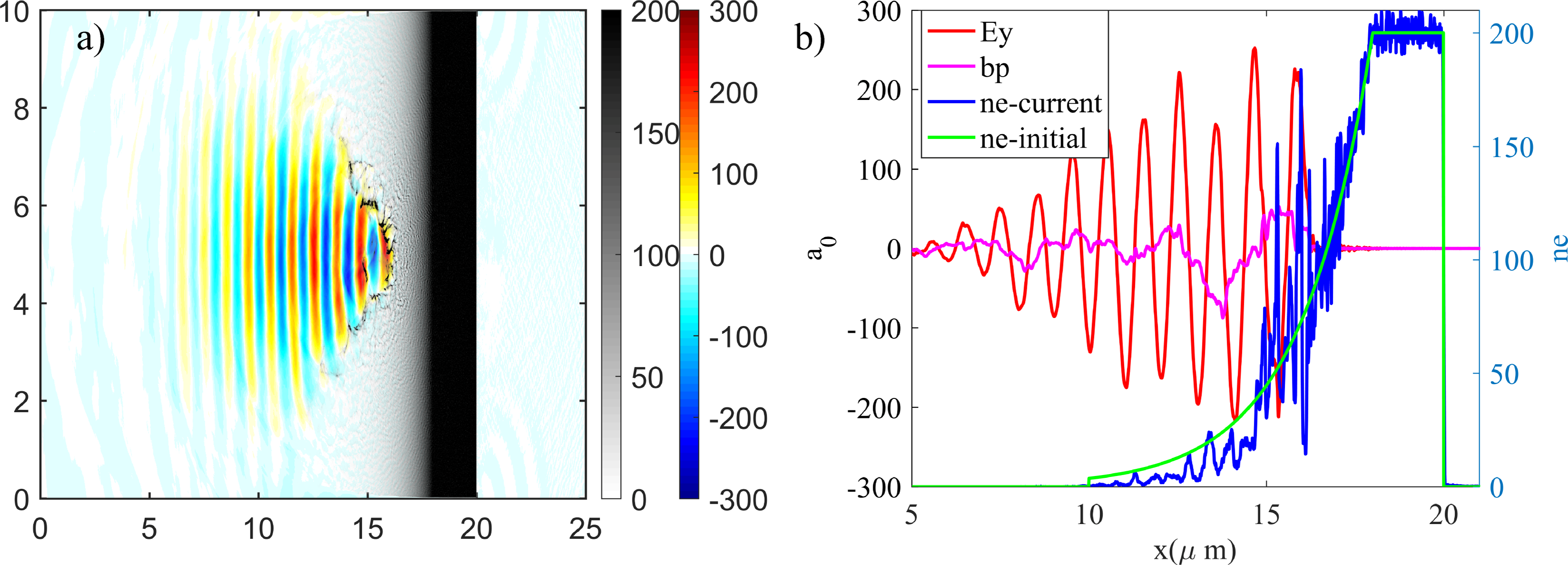
Figure 6 (a) The electron density (black to white colorbar) and laser field Ey
(red to blue colorbar) distribution of the preplasma scale length L = 2
![]() $\lambda$
condition at characteristic time; (b) lineplot in the position of y = 5 µm for the laser field Ey
, reflected laser field bp (bp =
$\lambda$
condition at characteristic time; (b) lineplot in the position of y = 5 µm for the laser field Ey
, reflected laser field bp (bp =
 $\left({E}_y-c{B}_z\right)/2$
), and electron density (blue is the current distribution and green is the initial profile).
Increasing the preplasma scale length to L = 4
![]() $\lambda$
, the characteristics of electrons and γ-rays are similar to the case of L = 2
$\lambda$
, the characteristics of electrons and γ-rays are similar to the case of L = 2
![]() $\lambda$
. From the Figures 4(d), 4(h), and 4(l), the majority of electrons are accelerated forward, emitting γ-rays in the underdense region density below
$\lambda$
. From the Figures 4(d), 4(h), and 4(l), the majority of electrons are accelerated forward, emitting γ-rays in the underdense region density below
![]() $74{n}_{\mathrm{c}}$
(x < 12λ) through Compton backscattering. Minor γ-rays are contributed by TOEE from transversely oscillating electrons in the dense plasma of 74n
c–120n
c (12λ < x < 16λ). The electrons and γ-rays are further collimated as illustrated in Figures 5(d) and 5(h). The expanding angles have changed from ±45° to nearly ±25° owing to increasing scale length. Although the angles are still quite large compared with other schemes[
Reference Stark, Toncian and Arefiev
38
,
Reference Zhu, Yu, Chen, Weng and Sheng
39
], the present simple layout is easier to perform in experiments such as the radiography of dense objects[
Reference Ben-Ismaïl, Lundh and Rechatin
40
].
$74{n}_{\mathrm{c}}$
(x < 12λ) through Compton backscattering. Minor γ-rays are contributed by TOEE from transversely oscillating electrons in the dense plasma of 74n
c–120n
c (12λ < x < 16λ). The electrons and γ-rays are further collimated as illustrated in Figures 5(d) and 5(h). The expanding angles have changed from ±45° to nearly ±25° owing to increasing scale length. Although the angles are still quite large compared with other schemes[
Reference Stark, Toncian and Arefiev
38
,
Reference Zhu, Yu, Chen, Weng and Sheng
39
], the present simple layout is easier to perform in experiments such as the radiography of dense objects[
Reference Ben-Ismaïl, Lundh and Rechatin
40
].
A simple analytical model is now presented to explain the continuous enhanced and collimated γ-ray emission with increasing preplasma scale length. When a linear-polarized laser penetrates the plasma, electrons are pushed forward by the ponderomotive force, which can be written as[ Reference Gibbon 41 ]
 $$\begin{align*}{F}_{p-x}=-\frac{m_{\mathrm{e}}{c}^2}{2{\mathrm{\gamma}}_{\mathrm{e}}}\frac{\delta {a}^2}{\delta x},\end{align*}$$
and oscillate at twice the laser frequency. In the longitudinal direction, electrons stop accelerating forward until the increasing electrostatic force is equal to the ponderomotive force. Under different preplasma scale length, electrons experience different acceleration lengths, which emit gamma photons mainly via SDE (L
1
= 0), SDE-like (L
2
= 0.5
![]() ${\lambda}$
), and Compton backscattering (L
3 =
${\lambda}$
), and Compton backscattering (L
3 =
![]() $2{\lambda}$
and L
4 =
$2{\lambda}$
and L
4 =
![]() $4{\lambda}$
) mechanisms. The ratio of the acceleration distance can be estimated approximately by the scale length ratio as L
1
:L
2
:L
3
:L
4
(L corresponding to the preplasma scale length). The final electron velocity in the longitudinal direction is proportional to the square root of the preplasma scale length. Moreover, the electrons also oscillate in the transverse direction with the laser cycle as exhibited in traditional SDE and TOEE mechanisms. Using simulation data and analytical calculations, we finally arrive at a rough ratio of the electron velocity
$4{\lambda}$
) mechanisms. The ratio of the acceleration distance can be estimated approximately by the scale length ratio as L
1
:L
2
:L
3
:L
4
(L corresponding to the preplasma scale length). The final electron velocity in the longitudinal direction is proportional to the square root of the preplasma scale length. Moreover, the electrons also oscillate in the transverse direction with the laser cycle as exhibited in traditional SDE and TOEE mechanisms. Using simulation data and analytical calculations, we finally arrive at a rough ratio of the electron velocity
 ${v}_{x1}:{v}_{x2}:{v}_{x3}:{v}_{x4}:{v}_y=1:1:\sqrt{2}:2:1,$
corresponding to the expanding angles
![]() ${\alpha}_1=45{}^{\circ},\,{\alpha}_2=45{}^{\circ},\,{\alpha}_3=35{}^{\circ},\; {\rm and\;}\; {\alpha}_4=27{}^{\circ},$
which are in good agreement with the angular distributions of energetic electrons and gamma photons shown in Figure 5.
${\alpha}_1=45{}^{\circ},\,{\alpha}_2=45{}^{\circ},\,{\alpha}_3=35{}^{\circ},\; {\rm and\;}\; {\alpha}_4=27{}^{\circ},$
which are in good agreement with the angular distributions of energetic electrons and gamma photons shown in Figure 5.
Returning to simulation, the temporal profiles of conversion efficiency from laser energy to electrons and γ-rays are shown in Figure 7. The longer scale length obtains the highest conversion efficiency, although it seems that the L = 4λ case has the saturation tendency relative to that of the L = 2λ case. Thus, we scan a large parameter region to find the scale law between γ-ray conversion efficiency and scale length, which is shown in Figure 8.
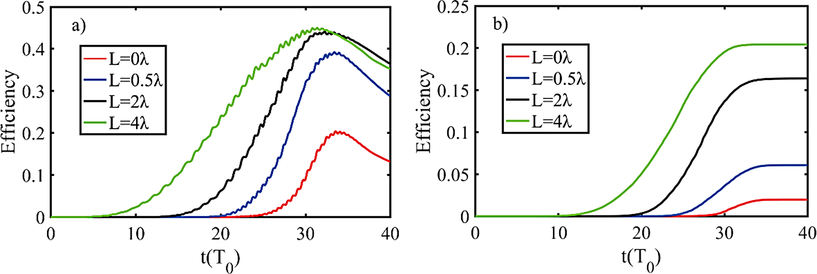
Figure 7 The conversion efficiency of laser energy to (a) electrons and (b) γ-rays at various preplasma scale lengths.
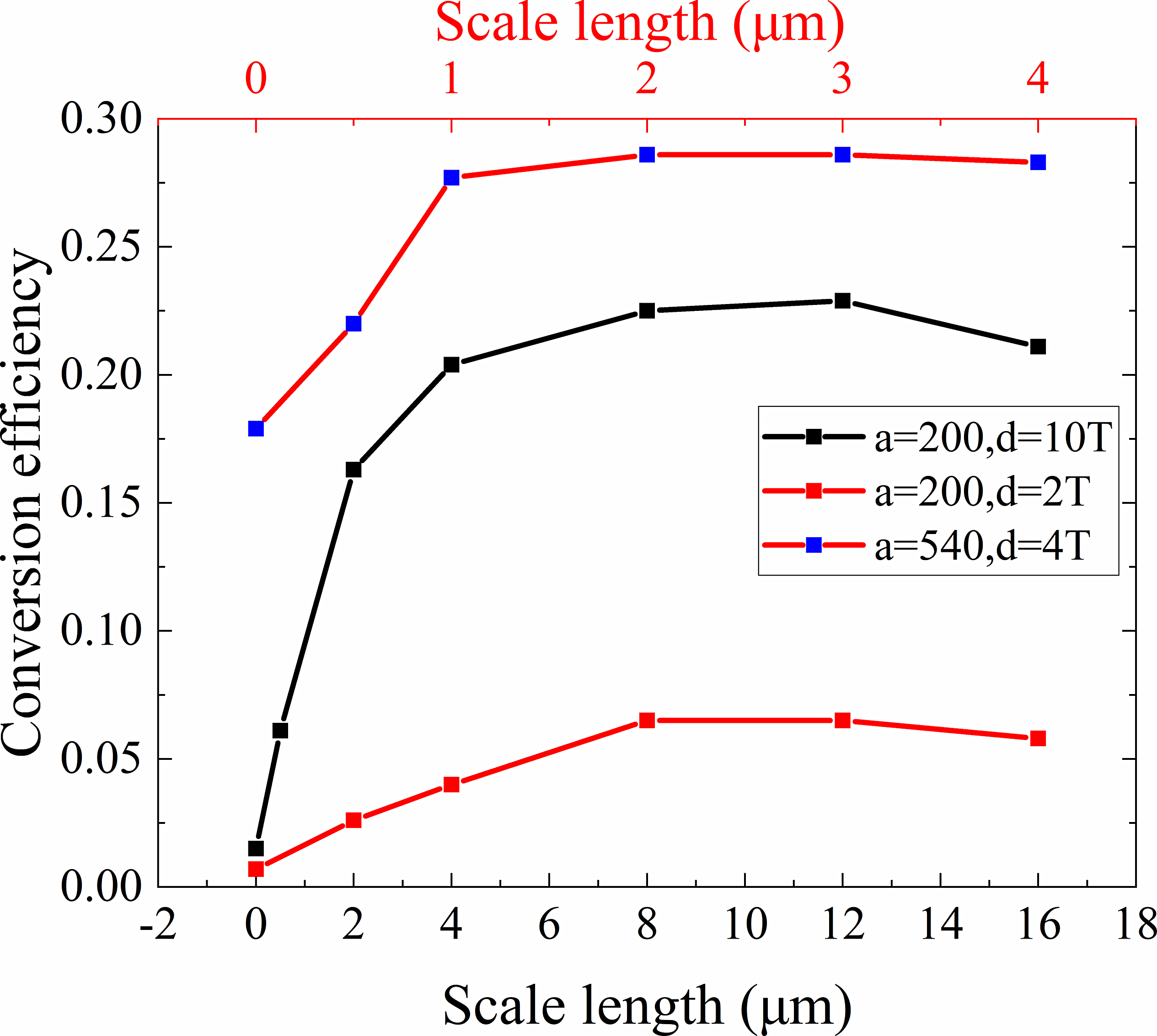
Figure 8 The conversion efficiency from laser energy to γ-rays at different scale lengths and laser parameters. The conversion efficiencies are saturated at longer scale lengths (d is the laser pulse width (FWHM) and T = 3.3 fs is the laser period for
![]() $\lambda =1\ \mathrm{\mu} \mathrm{m}$
).
$\lambda =1\ \mathrm{\mu} \mathrm{m}$
).
As can be found in Figure 8, with increasing scale length, the conversion efficiency first increases owing to the longer acceleration length, then reaches a saturated region, and finally decreases slightly at various laser parameters. The saturation phenomenon is a natural result of the piled plasma mirror. The γ-rays are the combined effect of forward electron acceleration and backward laser field reflected by piled plasma. At small scale length, the short acceleration length limits the electron energy and the γ-ray emission. At very long scale length, the plasma accumulation and the piled plasma mirror are not formed in time owing to over-attenuated preplasma, which decreases the reflected laser field and the γ-ray emission, although it has more energetic electrons. Thus, the optimal scale length of γ-ray generation is the balance between acceleration of electrons and laser reflection.
From Figure 8 we also find the positive correlation between the optimal scale length and laser pulse duration. A shorter laser pulse needs to be reflected by piled plasma early to serve as the background field for the accelerated electrons before the laser energy is depleted. On the other hand, longer laser duration can accelerate electrons fully before the laser reflected because the longer pulse contains more energy to accelerate electrons and act as a background field. Meanwhile, the formation time of piled plasma mirror and the scale length are proportionate. Therefore, the optimal scale length for a long pulse is nearly five times that of a short pulse (as shown in Figure 8 for a = 200), which is a multiple of the duration time.
5 Conclusion
In summary, we have investigated the influence of preplasma scale length on γ-ray emission in the interaction between an ultraintense laser and solid targets via 2D PIC simulation. We find that the preplasma will enhance and collimate the γ-ray emission significantly. It exhibits the formation of piled plasma mirror, which has the same function as plasma mirror in an all-optical Compton backscattering scenario. The forward-accelerated electrons interact with the backward laser field reflected by the piled plasma in the preplasma region and produce the γ-ray emission. A solid target with appropriate preplasma could be robust to generating a useful γ-ray source, which is easier for experimental operation. The feature may be slightly different in an actual 3D situation, but the primary physical characterization will be maintained[ Reference Lezhnin, Sasorov, Korn and Bulanov 15 ]. The current study may be conducted in PW facilities such as SULF and ELI, and is helpful for future experiments, especially for bright collimated γ-ray source generation, and it may also be used to diagnose the preplasma according to the features of the emitted γ-rays.
Acknowledgments
We acknowledge M. Chen for fruitful discussions. This work was supported by the Strategic Priority Research Program of the Chinese Academy of Sciences (No. XDB16000000), the National Natural Science Foundation of China (Nos. 11775223, 11375197, 11605200, and 11275202), the National Key Program for S&T Research and Development (No. 2018YFA0404804), the Science Challenge Project (No. TZ2016005), and the Open Fund of the State Key Laboratory of High Field Laser Physics (SIOM).


