1. Introduction
High-power single-frequency lasers have unique properties such as low phase noise, narrow spectral linewidth and excellent beam quality, making them indispensable in many advanced scientific and technological applications[ Reference Li, Tao, Jiang, Ma, Liu, Su, Xu, Leng and Zhou1]. The demand for high-power single-frequency lasers is particularly pronounced in applications requiring coherent detection and long-distance transmission, where maintaining signal integrity over extended distances is critical. For example, in gravitational wave detection, the lasers must be capable of transmitting over long distances within the interferometer arms, which can extend several kilometers to detect the tiny disturbances in spacetime caused by gravitational waves[ Reference Steinke, Tünnermann, Kuhn, Theeg, Karow, Varona, Jahn, Booker, Neumann, Weßels and Kracht2]. In light detection and ranging (LIDAR) systems, they are crucial for the detection and processing of weak backscattered signals from distant objects[ Reference Zhang, Liu, Stephens and Eggleton3]. In optical communications, long-distance transmission is vital to connect distant communication nodes while preserving the quality and coherence of the transmitted signal[ Reference Okamoto, Terayama, Yoshida, Kasai, Hirooka and Nakazawa4]. In high-precision metrology, including frequency combs and atomic clocks, the lasers are required to be transmitted to remote locations for precise measurements[ Reference Oelker, Hutson, Kennedy, Sonderhouse, Bothwell, Goban, Kedar, Sanner, Robinson, Marti, Matei, Legero, Giunta, Holzwarth, Riehle, Sterr and Ye5].
One of the primary challenges in transmitting high-power single-frequency lasers over long distances through optical fibers is the onset of nonlinear effects, particularly stimulated Brillouin scattering (SBS)[ Reference Kobyakov, Sauer and Chowdhury6, Reference Smith7]. SBS is a nonlinear optical effect where the interaction between the light and acoustic waves in the fiber leads to the generation of backscattered Stokes waves. This process becomes highly efficient at a certain threshold power, leading to a rapid increase in back-reflected light intensity, which can severely limit the maximum power that can be transmitted through the fiber. Effective suppression of SBS can enable higher power levels and longer transmission distances, which are essential for improving the performance and reliability of these systems. Various techniques, including the use of fibers with tailored acoustic speed profiles[ Reference Gray, Walton, Chen, Wang, Li, Liu, Ruffin, Demeritt and Zenteno8] and segmented fiber links[ Reference Kobyakov, Sauer and Hurley9], have been explored to enhance the SBS threshold and mitigate its effects. Nonetheless, the inherent nonlinearity of traditional solid-core fibers and the complexity of SBS remain significant obstacles to the efficient and reliable transmission of high-power single-frequency lasers over long distances[ Reference Li, Tao, Jiang, Ma, Liu, Su, Xu, Leng and Zhou1, Reference Kobyakov, Sauer and Chowdhury6].
The advent of hollow-core fibers (HCFs) has introduced a promising alternative for high-power laser delivery[ Reference Wang, Alharbi, Bradley, Fourcade-Dutin, Debord, Beaudou, Gerôme and Benabid10]. HCFs confine light within an air or vacuum core, substantially reducing the interaction between the light and the fiber material[ Reference Russell11, Reference Benabid and Roberts12]. This characteristic significantly reduces the nonlinear optical effects, such as SBS, stimulated Raman scattering (SRS) and Kerr effects, making HCFs highly suitable for high-power laser applications. However, early HCF designs, such as photonic bandgap fibers, had a core mode-field overlap with the silica membrane of 0.1%[ Reference Roberts, Couny, Sabert, Mangan, Williams, Farr, Mason, Tomlinson, Birks, Knight and Russell13]. Transmission of high power is still impossible because of this high overlap, as well as its multimode nature and relatively high loss[ Reference Poletti, Petrovich and Richardson14]. Recent advancements in anti-resonant hollow-core fibers (AR-HCFs) have drastically improved the performance of HCFs[ Reference Ding, Wang, Gao, Wang and Wang15]. They have reduced the overlap between the light field and the silica membrane to as low as less than 0.01%, significantly decreasing the potential for material damage even at high power levels[ Reference Fokoua, Mousavi, Jasion, Richardson and Poletti16]. Moreover, the lowest reported loss for AR-HCFs has reached an impressive value, 0.11 dB/km[ Reference Chen, Petrovich, Fokoua, Adamu, Hassan, Sakr, Slavík, Gorajoobi, Alonso, Ando, Papadimopoulos, Varghese, Wu, Ando, Wisniowski, Sandoghchi, Jasion, Richardson and Poletti17], making them highly suitable for long-distance applications. Several works have been reported in this direction, including 1 kW level continuous wave transmission over a 1 km long AR-HCF[ Reference Mulvad, Mousavi, Zuba, Xu, Sakr, Bradley, Hayes, Jasion, Fokoua, Taranta, Alam, Richardson and Poletti18], narrow-linewidth transmission of 2.2 kW over a 100 m long AR-HCF[ Reference Cooper, Wahlen, Yerolatsitis, Cruz-Delgado, Parra, Tanner, Ahmadi, Jones, Habib, Divliansky, Antonio-Lopez, Schülzgen and Correa19] and multimode transmission of 3 kW level laser power over a 10 m AR-HCF[ Reference Yao, Zhang, Li, Wang, Jin, Duan, Zhao and Wang20]. These achievements highlight the potential of AR-HCFs to overcome the limitations of solid-core fibers.
Despite these advancements, almost all high-power laser transmission setups with AR-HCFs have relied on free-space coupling techniques[ Reference Mulvad, Mousavi, Zuba, Xu, Sakr, Bradley, Hayes, Jasion, Fokoua, Taranta, Alam, Richardson and Poletti18– Reference Yao, Zhang, Li, Wang, Jin, Duan, Zhao and Wang20]. These setups have inherent drawbacks. Nowadays, most high-power laser systems have all-fiber architecture. However, the benefit of compactness has been compromised by the use of AR-HCF. Furthermore, the free-space coupling systems are susceptible to thermal lensing effects at high power, which can shift the focal point and complicate alignment[ Reference Yao, Zhang, Li, Wang, Jin, Duan, Zhao and Wang20, Reference Dobek21]. These issues are particularly problematic in applications where long-term stability and operation in dynamic environments are required.
In the context of single-frequency fiber lasers or amplifiers, the current state-of-the-art power levels are still below 1 kW, with 500–800 W at the research level[ Reference Shi, Deng, Fu, Sheng, Jiang, Shi, Li, Shi and Yao22– Reference Lai, Ma, Liu, Huang, Li, Ma and Zhou25] and 100 W at the commercial level. At the application end, high-precision metrology, optical communication, LIDAR systems and gravitational wave detection place high demands on the stability, portability and transmission length of the laser systems.
This paper aims to demonstrate SBS-free delivery of 100 W single-frequency laser power over a 100 m AR-HCF using an all-fiber architecture. Experimentally, a transmission efficiency of 92% is achieved using a mode-field matched AR-HCF with loss of less than 1 dB/km. The results and methods described herein offer significant advancements in the field of high-power single-frequency laser transmission, providing a robust solution for various high-precision and long-distance applications.
2. Fiber design and fabrication
In free-space setups, the selection of the mode-field diameter (MFD) for AR-HCF is not a critical consideration, as collimating lenses can be used to match the mode size of the laser beam with the fiber’s MFD. Conversely, in an all-fiber format, mismatches in the MFD between fibers substantially degrade the coupling efficiency. To match the MFD of AR-HCF, post-processing techniques such as up-tapering[ Reference Wang, Yu, Debord, Gérôme, Benabid, Chiang and Xiao26], thermal-expanded cores[ Reference Zhang, Ding, Jia, Hong, Chen, Sun, Gao, Huang and Wang27] or inserting intermediate fibers, such as graded-index (GRIN) fibers[ Reference Suslov, Komanec, Fokoua, Dousek, Zhong, Zvánovec, Bradley, Poletti, Richardson and Slavík28], are commonly applied. Although these techniques are mature for the single-mode fiber, they become quite complicated for the large-mode-area polarization-maintaining panda fiber used for high-power single-frequency lasers. Up-tapering and the thermal-expanded core technique, both of which require heating the fiber, are challenges to panda fibers due to the presence of boron-doped stress rods that can diffuse and alter the fiber structure under heat. GRIN fibers necessitate extremely precise cutting as well as alignment and can degrade single-mode properties if not executed perfectly. Down-tapering of HCF[ Reference Zheng, Debord, Vincetti, Beaudou, Gérôme and Benabid29] is possible but introduces additional complexities, as the air holes in the fiber can easily collapse when exposed to flames, making the tapering process highly delicate and prone to introducing losses and mechanical weaknesses.
To bypass the complications and potential performance degradation associated with post-processing techniques, AR-HCF having an MFD matching that of the panda fiber is intentionally designed and fabricated. The commercial finite-element method solver Comsol Multiphysics is used to simulate the fundamental mode profile of the large-mode-area panda fiber (Coherent, PLMA-GDF-25/250-M) with a fixed core diameter of 25 μm and the AR-HCF with varying core diameter (D core) ranging from 20 to 40 μm[ Reference Selleri, Vincetti, Cucinotta and Zoboli30]. The insertion loss at the butt-coupled junctions was calculated using the formula in Ref. [Reference Aghaie, Digonnet and Fan31]. This calculation involved determining the field transmission coefficient,
which leads to a coupling loss defined as L = 1 – |tran.|2. Here, E i, H i (E t, H t) are the normalized electronic and magnetic field vector of the fundamental mode (FM) of the panda fiber (AR-HCF), respectively. Their normalization is expressed as follows:
 $$\begin{align}\left\langle {E}_{\mathrm{i}(\mathrm{t})}|{H}_{\mathrm{i}(\mathrm{t})}\right\rangle =\frac{1}{2}\operatorname{Re}\left(\int \mathrm{d}A\left({E}_{\mathrm{i}(\mathrm{t})}\times {H}_{\mathrm{i}(\mathrm{t})}^{\ast}\right)\cdot \hat{z}\right)=1,\end{align}$$
where A represents the cross-sectional area of the fiber.
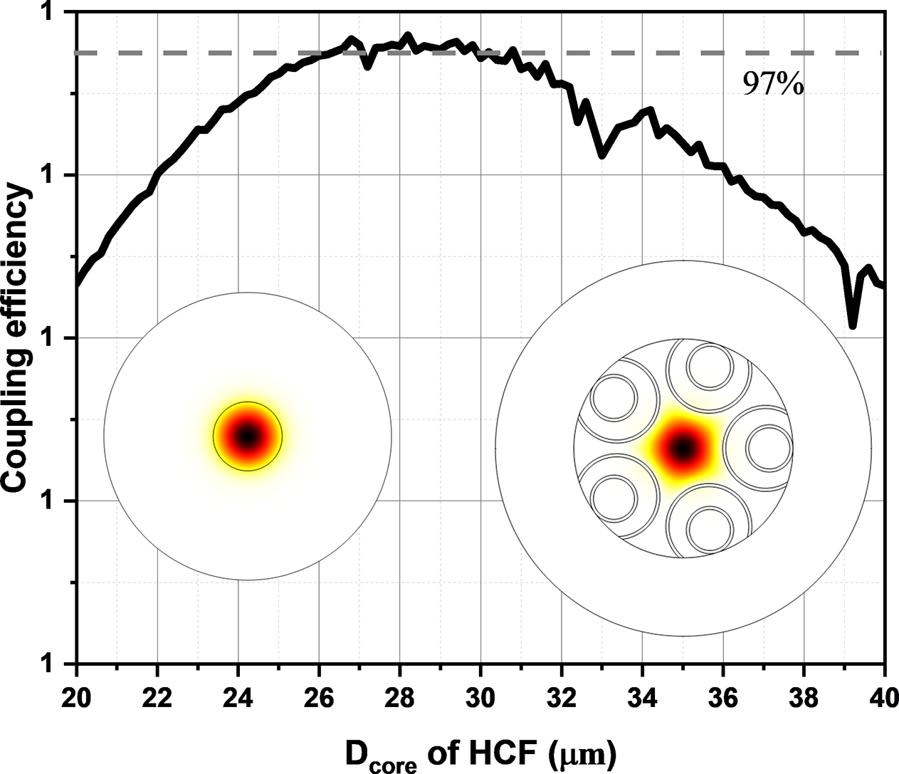
The stress rods are excluded from the simulation since they do not influence the MFD. The simulation results, shown in Figure 1, indicate that when the D core is within the range of 26–30 μm, the theoretical coupling efficiency exceeds 97%, corresponding to a coupling loss of 0.13 dB. This gives a relatively broad tolerance margin for fiber fabrication.

Figure 1 Calculated coupling efficiency between the PLMA-GDF-25/250-M and AR-HCF with varying core diameter ranging from 20 to 40 μm. The mode-field profile is simulated via finite element method.
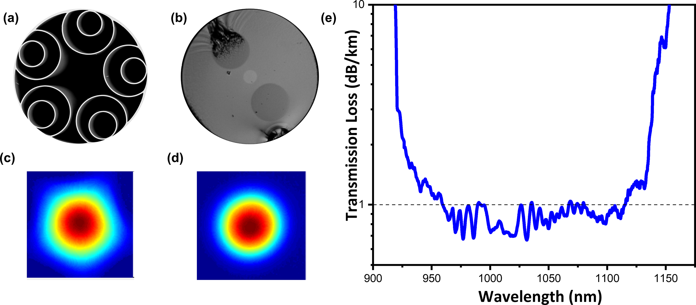
Our fiber design incorporated the truncated nested anti-resonant nodeless fiber (T-NANF)[ Reference Gao, Chen, Sun, Ding and Wang32] with operating wavelength tailored to 1064 nm and D core within the designed range. Figure 2(a) shows a scanning electron microscope (SEM) image of the in-house fabricated AR-HCF using the stack-and-draw technique with a core diameter of 30 μm, outer diameter of 230 μm and glass membrane thickness of 860 ± 10 nm. The fiber loss was measured using the cut-back method from 300 to 20 m with a supercontinuum source and an optical spectrum analyzer (OSA), showing a loss level of less than 1 dB/km from 960 to 1115 nm (Figure 2(e)). We then experimentally measured the near-field pattern of the panda fiber and AR-HCF, as shown in Figures 2(c) and 2(d). Using Equation (1) to calculate their coupling efficiency based on the measured patterns, we obtained a value of 95% (coupling loss of 0.22 dB). This is slightly lower than the simulated result, likely due to the distortion in the measured pattern, but it remains sufficiently high for laser transmission applications.

Figure 2 (a) SEM image of the in-house fabricated AR-HCF. (b) Microscope image of PLMA-GDF-25/250-M. Their near-field patterns are shown in (c) for AR-HCF and (d) for PLMA-GDF-25/250-M. (e) Measured transmission loss spectrum of the AR-HCF.
3. Power delivery
To investigate the power delivery performance of AR-HCF, a polarization-maintaining single-frequency all-fiber laser comprising a seed laser and two amplifiers is utilized with a center wavelength of 1064 nm, a linewidth of 12 kHz, an M 2 factor of 1.22 and an output power of 110 W (Figure 3(a)). The panda fiber at the output end was angle-cleaved at 8 degrees to prevent detrimental back-reflected light effects on the laser and was inserted into a ceramic ferrule, secured with ultraviolet (UV)-curable glue. For the 100 m AR-HCF, following the meticulous assembling procedure we developed in Ref. [Reference Zhang, Ding, Jia, Hong, Chen, Sun, Gao, Huang and Wang27], its input end is also fixed into a ceramic ferrule with a flat-cleave and cured with UV glue. The two ferrules are then mounted on a custom fixture and coupled through a five-axis adjustment stage. The fiber bending radius was maintained at 15 cm, and the coating layer on approximately 10 cm of the AR-HCF input end was stripped to reduce the risk of thermal damage from uncoupled light. Once optimal coupling efficiency was achieved at a low power level, the ceramic ferrules at both ends of the coupling point were UV-cured onto a high-hardness, thermally conductive base (Figure 3(b)) for packaging. Throughout all procedures, a UV adhesive with an extremely low expansion coefficient and high-temperature resistance was used, ensuring that the coupling efficiency was not compromised during curing and under high input power. The resulting packaged panda fiber to hollow-core coupler (Figure 3(c)) demonstrated our reliable, high-efficiency and high-quality assembly.

Figure 3 (a) Schematic setup for power delivery. The single-frequency laser is composed of the seed, amplifier 1 and amplifier 2. The output of the laser is butt-coupled to the AR-HCF via ceramic ferrules on a five-axis adjustment stage. Two power meters monitor the backward and transmitted power intensity. (b) Packaging of the coupled AR-HCF and PLMA-GDF-25/250-M onto a high-hardness thermally conductive base with UV-curable glue. (c) Packaged PLMA-GDF-25/250-M and AR-HCF coupler. (d) Thermal imaging of the coupling area under maximum input laser power of 108 W.
For monitoring purposes, power meter 1 (PM1) is placed at the output of the Faraday isolator to monitor the intensity of reflected and backscattered light through an optical coupler. PM2 is placed at the output end of the panda fiber to record the input powers before launching and then at the output end of the AR-HCF after launching (Figure 3(a)).
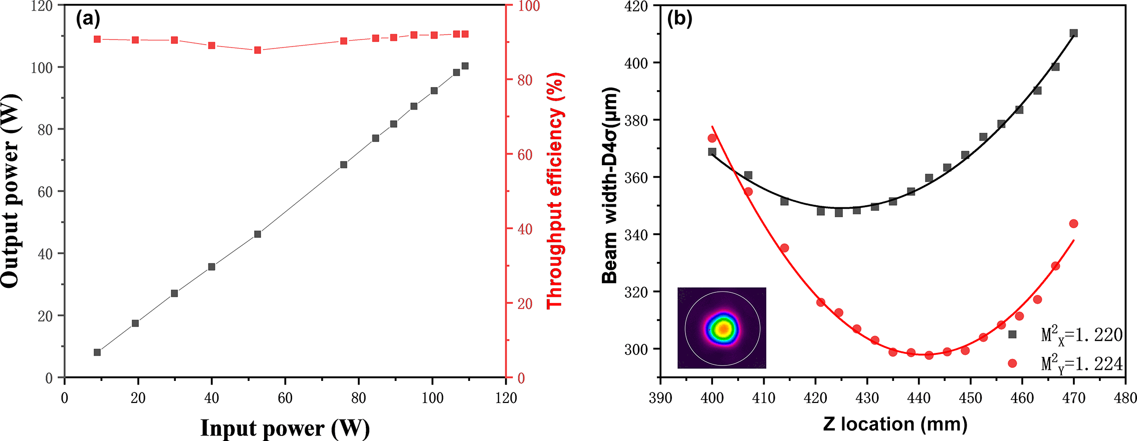
Figure 4(a) shows the power delivery results. When the laser output is around 8 W, the transmission efficiency is 90%, likely due to measurement inaccuracies when using a 500 W power meter to measure low power levels. At the maximum laser output of 108.9 W, the output after 100 m of the fiber is 100.3 W, resulting in a transmission efficiency of 92% or a total insertion loss of 0.36 dB. This includes a fiber transmission loss of 0.1 dB and a coupling loss of 0.26 dB, matching well with the calculated coupling efficiency in the previous section. Throughout the experiment, the output power remained stable. Thermal imaging of the coupling area in Figure 3(d) shows that, at maximum laser power input, the maximum temperature at the coupling point does not exceed 90 degrees. To evaluate beam quality, a part of the output 100 W light is reflected into a beam quality analyzer, showing an M 2 factor of 1.22 (Figure 4(b)). The fact that both the laser and the fiber are single mode with similar M 2 factors also explains why such high coupling efficiency can be obtained.

Figure 4 (a) Output power and throughput efficiency as functions of input pump power. (b) Beam quality and near-field pattern at maximum laser power output.

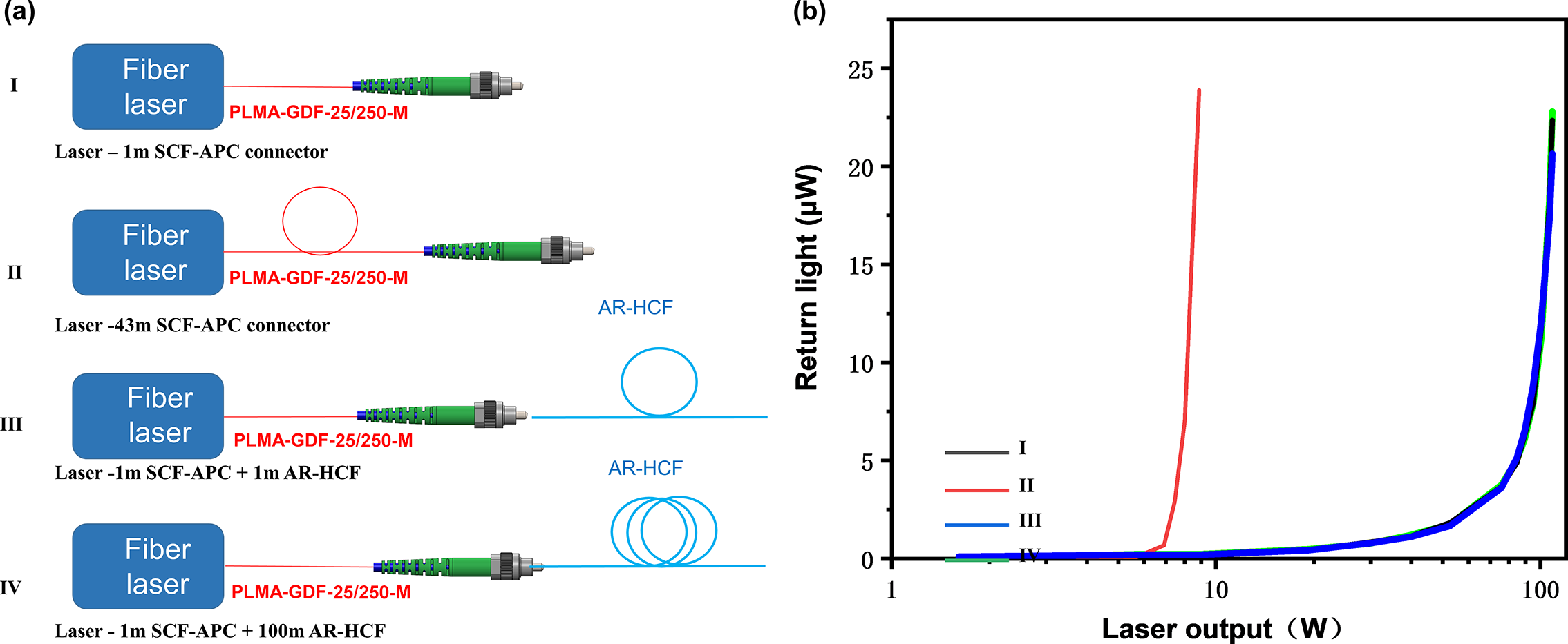
Figure 5 (a) Comparison of high-power single-frequency laser transmission through four different lengths of PLMA-GDF-25/250-M and AR-HCF: (I) 1 m panda fiber; (II) 43 m panda fiber; (III) 1 m panda fiber and 1 m HC-ARF; (IV) 1 m panda fiber and 100 m HC-ARF. (b) Back-reflected light intensity curves from the four configurations. Note here that the I, III and IV curves strongly overlap.
Due to the lack of equipment for directly measuring the laser linewidth, we used the backward light intensity to indirectly assess whether the linewidth has been broadened and whether backward SBS was generated. This method is widely used in single-frequency lasers for SBS monitoring[ Reference Li, Tao, Jiang, Ma, Liu, Su, Xu, Leng and Zhou1, Reference Shi, Deng, Fu, Sheng, Jiang, Shi, Li, Shi and Yao22]. We conducted four comparative experiments involving both solid-core and HCFs. As illustrated in Figure 5(a), Configuration I uses a 1 m angled physical contact (APC) connector with panda fiber; Configuration II extends the length of the APC to 43 m; Configuration III involves coupling 1 m of AR-HCF to a 1 m APC connector using a five-axis adjustment stage; Configuration IV couples 100 m of AR-HCF to a 1 m APC connector using the same adjustment stage. As shown in Figure 3(a), PM1 is used to record the intensity of the back-reflected light for each experiment as the power increased. This backward light mainly comes from two sources: the Fresnel reflection from the APC end face and the backward Stokes light generated by SBS. The results of the back-reflected light from the four configurations are shown in Figure 5(b), showing that the back-reflected light intensity curves for Configurations III and IV overlap with that of Configuration I, with a sharp increase around 100 W. We interpreted this sharp increase as the threshold of SBS generation in the first 1 m APC connector. Delivering the single-frequency laser through AR-HCF, whether for a short length of 1 m or a long length of 100 m, does not generate any additional SBS effects thanks to the extremely low nonlinearity of the AR-HCF. In contrast, the curve for Configuration II showed a sharp increase at a power level as low as 8.5 W, indicating that increasing the length of the solid-core fiber significantly reduces the SBS threshold, as shown in numerous studies[ Reference Kobyakov, Sauer and Chowdhury6].
Due to the limited fiber length and laser power, the SBS threshold for AR-HCF was not quantitatively determined in this experiment. However, it is speculated that the delivery length can extend to the kilometer level with much higher input power by improving the coupling efficiency or implementing water cooling to the coupling point. The nonlinear coefficient of HCF is more than three orders of magnitude lower than that of solid-core fiber, making it an ideal choice for single-frequency laser transmission.
4. Discussion and conclusion
In this study, we successfully demonstrate SBS-free all-fiber transmission of a 100 W single-frequency, single-mode laser over 100 m of AR-HCF. The transmission achieves an output power of 100.3 W, a spectral linewidth of 12 kHz, a central wavelength of 1064 nm, a beam quality factor (M 2) of 1.22 and a transmission efficiency of 92%. These results were enabled by a low-loss AR-HCF designed with a matched MFD, which is in-house fabricated with a loss of 1 dB/km at 1064 nm. The all-fiber configuration ensures a compact transmission system.
Looking forward, there is potential to further increase the input power and extend the fiber length. In an all-fiber format, the transmission power is primarily limited by the coupling condition, rather than the laser-induced damage threshold of the AR-HCF itself. One approach is to design AR-HCFs with a better match to the MFD and shape of solid-core fibers to reduce the coupling losses. It has been shown that increasing the number of nested tubes in the cladding can help achieve a more circular mode shape[ Reference Zuba, Mulvad, Slavík, Sakr, Poletti, Richardson and Fokoua33], although this may introduce high-order mode issues. In addition, implementing active water cooling systems could further increase the damage threshold. Regarding fiber length, at atmospheric pressure, the SBS nonlinear coefficient for air is three orders of magnitude lower than that of silica[ Reference Zhang, Feng, Marpaung, Fokoua, Sakr, Hayes, Poletti, Richardson and Slavík34], suggesting that the AR-HCF length could be extended to kilometers. Creating a vacuum environment within the AR-HCF could further reduce the SBS nonlinear coefficient, enabling even longer transmission lengths, possibly reaching several tens of kilometers. The specific requirements for length, power and portability will depend on different application needs, such as high-precision metrology, optical communication, LIDAR systems and gravitational wave detection.
Acknowledgements
This work was supported by the National Natural Science Foundation of China (Grant Nos. 62222506, 62105122 and U21A20506), and in part by the Basic and Applied Basic Research Foundation of Guangdong Province (Grant Nos. 2021B1515020030, 2021A1515011646 and 2022A1515110218) and in part by the Guangzhou Science and Technology Program (Grant No. 2024A04J9899).


