Research Article
An Apparatus for Determining Coefficients in Power Series
-
- Published online by Cambridge University Press:
- 31 October 2008, pp. i-iii
-
- Article
-
- You have access
- Export citation
The Latus Rectum of the Parabola: (ax + by)2 + 2gx + 2fy + c = 0
-
- Published online by Cambridge University Press:
- 31 October 2008, p. iv
-
- Article
-
- You have access
- Export citation
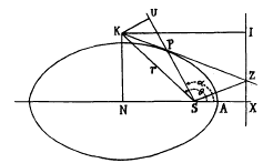
The Polar Equation of the Tangent and Normal to a Conic
-
- Published online by Cambridge University Press:
- 31 October 2008, pp. v-vi
-
- Article
-
- You have access
- Export citation
A Problem in Confocals
-
- Published online by Cambridge University Press:
- 31 October 2008, pp. vi-vii
-
- Article
-
- You have access
- Export citation
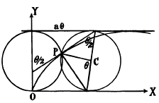
Note on a Property of the Cycloid
-
- Published online by Cambridge University Press:
- 31 October 2008, p. viii
-
- Article
-
- You have access
- Export citation
Note on Continued Fractions and the Sequence of Natural Numbers
-
- Published online by Cambridge University Press:
- 31 October 2008, pp. ix-xiii
-
- Article
-
- You have access
- Export citation
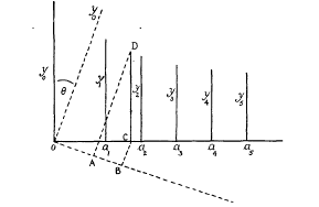
Note on Polynomial Interpolation
-
- Published online by Cambridge University Press:
- 31 October 2008, pp. xiii-xv
-
- Article
-
- You have access
- Export citation
A Note on Mathematical Expectation
-
- Published online by Cambridge University Press:
- 31 October 2008, pp. xv-xvi
-
- Article
-
- You have access
- Export citation
A Simple Method of Finding Sums of Powers of the Natural Numbers
-
- Published online by Cambridge University Press:
- 31 October 2008, pp. xvi-xix
-
- Article
-
- You have access
- Export citation


 = cos (θ —
  where λ

 12S
12S