


Introduction
The grounding line is defined where ice flowing into a water body decouples from the glacier bed and, due to buoyancy, starts to float (Reference WeertmanWeertman, 1974). In reality, there is often a zone in which the ice is intermittently grounded depending on the state of the tide. This area is referred to as the grounding zone and is characterized in the glacial ice by narrowstr and cracks at the ice surface and changes in slope. Field surveys, radio-echo sounding and the analysis of optical imagery have traditionally been used to locate the grounding zone (Reference RoseRose, 1979; Reference Bindschadler, Stephenson, MacAyeal and ShabtaieBindschadler and others, 1987a; Reference Shabtaie and BentleyShabtaie and Bentley, 1987; Reference Jacobel, Robinson and BindschadlerJacobel and others, 1994). The position of the grounding zone is related to ice thickness, density, local drainage patterns, sea level and bathymetry. It is important to locate the grounding line precisely because it provides a reference for monitoring changes in ice thickness and sea level (Reference Thomas and BentleyThomas and Bentley, 1978; Reference RignotRignot, 1998). Grounding-zone information is also required for sub-ice-shelf modelling of tides and currents.
Satellite radar interferometry (SRI) measures relative line-of-sight displacement between multiple synthetic aperture radar (SAR) image acquisitions. The rise and fall of ocean tides produces vertical displacement of floating ice, and under the right circumstances SRI can be used to define the boundary between the grounded and floating ice of an ice shelf. Successful mapping of grounding zones has been achieved with the European Space Agency ERS satellites (Reference Goldstein, Engelhardt, Kamb and FrolichGoldstein and others, 1993; Reference Hartl, Thiel, Wu, Doakeand and SieversHartl and others, 1994; Reference RignotRignot, 1996). An accuracy of 500m was achieved for the grounding line of the Rutford Ice Stream using two ERS-1data acquisitions 6 days apart (Reference Goldstein, Engelhardt, Kamb and FrolichGoldstein and others, 1993). Reference RignotRignot (1996) used multiple SRI pairs and double differencing to map the grounding zone of Petermann Gletscher, Greenland, with an accuracy of 20–80m. The premise is that horizontal ice motion should remain constant over time, while tidal flexing will usually vary between data acquisitions. Assuming constant horizontal ice motion, double differencing can remove the effect of both the horizontal motion and topography, and the spatial extent and magnitude of the tidal influence can then be measured accurately (Reference RignotRignot, 1996).
Prior to the 1997 CSA/NASA Antarctic Mapping Mission (AMM), SRI data were only available north of 79˚ S. RADARSAT looked to the left during the 30 day AMM, enabling the collection of geocoded imagery to the South Pole (Reference JezekJezek, 1999) and a limited SRI dataset suitable for ice-motion studies (Reference Gray, Mattar, Vachon and SteinGray and others, 1998; Reference JoughinJoughin and others, 1999). In this paper we use the AMM SRI data to improve grounding-zone mapping of parts of the southeast corner of the Ross Ice Shelf and the Filchner Ice Shelf.
Study Areas
Southeast corner of the Ross Ice Shelf
Concerns about the stability of the West Antarctic ice sheet (Reference OppenheimerOppenheimer, 1998; Reference Alley, Bindschadler, Alley and BindschadlerAlley and Bindschadler, 2001) have led to intensive study of the ice streams in the Siple Coast region of West Antarctica. The Crary Ice Rise (CIR) is a grounded feature in the southeast region of the Ross Ice Shelf downstream from the mouth of Whillans Ice Stream. An initial estimate of the grounding zone made by Reference RoseRose (1979) placed it relatively far inland and showed the CIR to be separated from the mainland by an area of floating ice. Both Reference Bindschadler, Stephenson, MacAyeal and ShabtaieBindschadler and others (1987a) and Reference Shabtaie and BentleyShabtaie and Bentley (1987, Reference Shabtaie and Bentley1988) identified areas of grounding downstream of Rose’s estimate, and the latter authors proposed a grounding zone that extended much further into the ice shelf, encompassing areas close to and beside the CIR. Further work by Reference BindschadlerBindschadler (1993), based on Système Probatoire pour l’Observation de la Terre (SPOT) imagery and fieldwork, improved the grounding-line mapping in some areas, but gaps and uncertainties still existed. Because the region is known to be dynamic (Reference Stephenson and BindschadlerStephenson and Bindschadler, 1988; Reference Fahnestock, Scambos, Bindschadler and KvaranFahnestock and others, 2000), temporal changes in the grounding zone might be anticipated. Studies of the area have shown that some sites upstream from the CIR have experienced a 50% decrease in velocity over the last three decades (Reference Bindschadler and VornbergerBindschadler and Vornberger, 1998) and that the ice plain (the lower region of Whillans Ice Stream and area upstream of the CIR) has been thickening, on average by 0.13 ±0.005ma–1 (Reference BindschadlerBindschadler and others, 1993). Close to and immediately upstream of the CIR, estimates of thickening have been as high as 2ma–1 (Reference Whillans, Bolzan and ShabtaieWhillans and others, 1987; Reference BindschadlerBindschadler, 1993).
The Filchner Ice Shelf
The Filchner Ice Shelf (FIS) is the eastern portion of the Filchner–Ronne Ice Shelf in the southern Weddell Sea. It periodically calves large tabular icebergs into the Weddell Sea (Reference Gammelsrød, Johannessen, Muench and OverlandGammelsrød and others, 1994) and also loses mass through the basal melting that contributes to the formation of Ice Shelf Water (ISW). The ISW plays a significant role in setting the properties of Antarctic Bottom Water which, in turn, plays a key role in global thermohaline circulation (Reference Foldvik, Gammelsrød, Slotsvik and TørresenFoldvik and others, 1985; Reference MikolajewiczMikolajewicz, 1998). Ice flow into and through the FIS has been studied by Reference Gray, Short, Mattar and JezekGray and others (2001) and Reference ZhaoZhao (2001). The flow-stripe pattern visible in both radar and optical imagery matches the current velocity field of the FIS, implying that the ice-flow pattern has been relatively stable for many hundreds of years. Reference Rignot, Padman, MacAyeal and SchmeltzRignot and others (2000) show that tidal models work reasonably well along the front of the Filchner–Ronne Ice Shelf, but that tidal predictions towards the back of the ocean cavity under these ice shelves vary depending on the chosen dataset for cavity geometry and grounding line.
Data And Method
Only some of the SAR data acquisitions were repeated during the 1997 AMM, and none of the study areas had more than one pair of images suitable for interferometry. For this reason the double-differencing technique (Reference RignotRignot, 1996) is not possible, and the grounding-zone mapping is much less accurate than is possible with multiple SRI pairs. Also, the 24 day repeat orbit of RADARSAT can be a disadvantage if there is a large velocity gradient across the grounding line. In this case there can be a loss of coherence, and other information must be used to estimate the grounding-line position. However, if coherence is maintained across the grounding zone then the 24 day image separation can be an advantage. Height differences of floating ice due to two of the most energetic tidal constituents, M 2 (period: 12.42 hours) and O 1 (period: 25.82 hours), are much larger for the 24 day pass separation than for 1day differences, since the phase of each constituent varies by only a few degrees per day relative to the satellite pass times. Consequently, the signal (the dense fringe pattern associated with the change in ice height across the grounding zone) is more likely to be stronger with a 24 day separation than with 1 day.
An Antarctic tidal model (Reference Padman and KottmeierPadman and Kottmeier, 2000; Reference Rignot, Padman, MacAyeal and SchmeltzRignot and others, 2000) was used to estimate the ice-height difference for the floating ice of both study areas between the times of the RADARSAT passes. This showed that for the two pairs of passes covering the FIS, the difference in ice height was in the range 1.5–2.5m. For the times of the two passes covering the CIR the tidal model predicted ice-height differences of 1–2m. Using the tidal-flexure model of Reference VaughanVaughan (1995), these figures imply a change in vertical position downstream from the grounding zone which would produce a dense pattern of many tens of fringes at the ERS or RADARSAT frequency. The interferogram phase was unwrapped to form a two-dimensional surface reflecting the relative change in line-of-sight range between corresponding pixels in the two images. The gradient of the unwrapped phase was calculated for both the range and azimuth (along-track) directions. Note that along-track phase gradient is not a measure of the along-track changes in ice displacement: interferogram phase relates only to line-of-sight displacements, i.e. both horizontal and vertical ice movement in the range plane. Either component of the phase gradient, however, is sensitive to changes in vertical displacement, with sensitivity determined by the orientation of the grounding line. Also, estimates of coherence are reduced when the phase is changing rapidly, because the phase will change over the window used to calculate coherence. In this way images of coherence can be complementary to the phase-gradient images in estimating the position of the grounding zone.
Errors in the grounding-line positions are related to the mapping accuracy and our ability to define the grounding-line position from the imagery. Despite the fact that no control points have been used and the georeferencing has been done using orbit, terrain-elevation and SAR ancillary data, the errors in the grounding-line position are still dominated by the subjective judgment made in defining the grounding line. The errors are discussed in the later sections but typically are in the range 1–2 km. While this is much poorer than is possible with the double-differencing technique, the results are still of value considering the current uncertainty in grounding-line position and the fact that it may be many years before regions south of *79˚ Sare mapped again by a SAR system suitable for double- differencing interferometry. Both the SAR imagery and the ice-surface elevation data (Reference Bamber and BindschadlerBamber and Bindschadler, 1997; Reference Jezek, Liu, Zhao and LiJezek and others, 2000) were used to help check the estimated positions.
Figure 1 shows images of the Ross Ice Shelf study area (*100 km 6200 km), enlargements of which have been used to map the grounding line. The darker, somewhat jagged band at the top of the coherence image (Fig.1b) has no counterpart in the SAR amplitude image (Fig. 1a) and corresponds to a band of strong phase gradient visible in Figure 1d and e. Interpretation of the interferometric phase (Fig.1c) is difficult at this scale. The phase of the small rectangle in the upper right of Figure 1c has been enlarged in Figure 1f. This shows the dense pattern of fringes indicative of the large phase gradients expected from the change in vertical movement associated with a grounding zone. The position of the grounding line is judged to be just at the upstream edge of the region of high phase gradient or associated lower coherence.
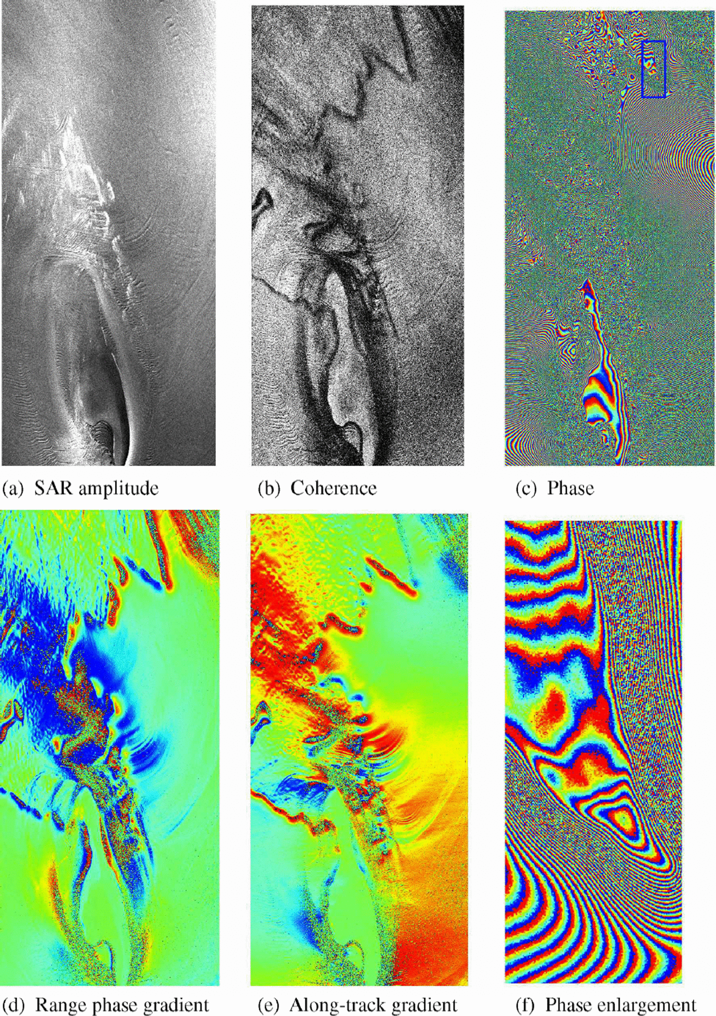
Fig. 1. (a) The SAR amplitude image of an area including the CIR (lower central part of the image) and the rougher, more heavily crevassed ice just upstream. (b) The coherence for the same region. Note that the dark bands (lower coherence) beginning at the top right and left side of (b) do not appear in (a). These bands correspond to the regions of high phase gradients shown in (d) and (e). (c) The interferometric phase. (d, e) The gradients of the phase in range (horizontal) and along-track (vertical), respectively . (f) An enlargement of the phase enclosed in the box in the upper right of (c).
Note the smooth character of the phase-gradient image for the floating ice (centre right in Fig. 1d and e) in relation to the more variable, mottled, character of the phase variations for the grounded ice (upper left). It is well known that phase variations in SRIcan be related to topography and terrain motion. For this pass the interferometric baseline is such that the phase variations over the grounded ice cannot be due to topography alone but must involve variations in ice motion coupled to the variations in topography. Measurements of surface topography in this area (Reference BindschadlerBindschadler, 1993) and study of SPOT imagery over time (R. Bindschadler and P. Vornberger, unpublished information) show that the surface topography does persist at particular locations with time. Consequently, horizontal motion of the ice will induce vertical movement leading to phase modulations (Reference Joughin, Winebrenner, Fahnestock, Kwok and KrabillJoughin and others, 1996). Reference BindschadlerBindschadler (1993) showed meter-scale surface height modulations extending over distances of a few kilometers. With a horizontal ice movement of around 26 m in the 24 days between data acquisitions (corresponding to ∼400ma–1), even the low slopes in this region will lead to vertical displacements sufficient to create the kind of phase fluctuations evident in Figure 1d and e.
Discussion Of The Southeast Ross Ice Shelf Results
Figure 2 compares the previous grounding-zone estimates with those derived from the interferometric results. The blue line shows the SRI-derived grounding line. A solid line indicates a 1–2 km confidence in positioning the line, while the dashed blue line corresponds to much lower confidence, as discussed below. An area of grounded ice delineated by the interferometric results appears to deflect the outflow of Scott Glacier from the Transantarctic Mountains to the west. Clear fringes were observed in this region equivalent to an ice-height variation which was consistent with the tidal-model prediction (Reference Padman, Fricker, Coleman, Howard and ErofeevaPadman and others, 2002).
Whether the ice in Ice Stream A just north of this region is grounded or not is hard to judge. While there are some fringes and the ice-surface elevation is relatively low, the exact position of the grounding line under Ice Stream A must await analysis of further data. However, the grounding zone further to the northwest can be identified. The solid blue line here reflects the results illustrated at the top of Figure 1b, d and e, and shows that the current grounding line is downstream of the earlier estimates. This may indicate an error in the earlier estimates, but it could also indicate an increase in the extent of grounded ice. Although there will be some horizontal change in ice speed across the grounding line, the tidally induced ice-height change was sufficient to create a fringe pattern which can be associated with the vertical motion. Again, the sense and approximate magnitude of the vertical movement obtained by fringe-counting was consistent with the tidal model.
In the central part of Figure 1c there are regions of high phase noise (presumably due to higher shear stresses), and the grounding-line mapping is much more difficult. Clearly, the ice ∼50km to the south of the CIR is floating and as one approaches the southwest flank of the CIR one can estimate the first area at which, possibly intermittently, grounding takes place. Consequently, the dashed blue line in this area represents an approximate estimate of the outer limit of ice grounding. There is also an indication of floating ice upstream of the CIR which has led to the inlet in the dashed line. The errors associated with the dashed line are unknown.
Previous work provided evidence of increased grounding in some areas, particularly just upstream of the CIR. Point G8 in Figure 2 was suggested to be floating in 1973 (Reference Robertson, Bentley, Hayes and BentleyRobertson and Bentley, 1984) but is considered grounded in Reference Shabtaie and BentleyShabtaie and Bentley (1987) and Reference BindschadlerBindschadler (1993). Point O, identified by Reference Bindschadler, MacAyeal, Stephenson, Van der Veen and OerlemansBindschadler and others (1987b) to be floating, may now be just grounded based on the phase results. Site E2 has also been identified by Reference BindschadlerBindschadler (1993) as an area which may have shown an increase in grounding. The suggestion that the grounding zone has recently expanded to incorporate these once-floating areas is supported by the significant ice thickening experienced in this region (Reference BindschadlerBindschadler, 1993). It is well known that both the ice and bed slopes in the ice plain are very low, and the ice thickness is close to, but just greater than, that required for buoyancy (Reference Shabtaie and BentleyShabtaie and Bentley, 1987). The possibility of a continuing increase in ice grounding is therefore consistent with both the increased ice thickness and a continuing decrease in the ice velocity (Reference Bindschadler and VornbergerBindschadler and Vornberger, 1998).

Fig. 2. Illustration of earlier grounding-zone estimates together with the position estimated from the SRI results. These data are superimposed on part of the AMM Antarctic mosaic. Blue is used to illustrate the SRI-derived grounding line, and other colors for the older estimates. A solid line indicates a 1–2 km mapping accuracy; a dashed line indicates that the interpretation is more difficult and the positional errors are unknown.
As the ice flows around the CIR the high strain rates, crevassing and resulting loss of coherence complicate the interpretation of the interferometric phase results. On the southwestern flank of the CIR it is difficult to map all the grounded areas. However, there does appear to be a water channel close to the CIR, consistent with the earlier data, as shown in Figure 2. The existence of a raft of ice moving northwards away from the CIR on the eastern flank was discussed by Reference Bindschadler, Vornberger, Stephenson, Roberts, Shabtaie and MacAyealBindschadler and others (1988). This region can be identified in the interferometric results, but we cannot positively confirm that there is grounded ice in this region. The existence of the grounding zone extending from the upstream end of the CIR to the west is, however, more clearly defined (Fig. 2). The integrity of this grounding zone is important to our conclusion that there does not appear to be a sub-ice water channel around the upstream end of the CIR.
Discussion Of The Fis Results
Figure 3 shows the grounding line taken from Reference VaughanVaughan and others (1995) in blue, together with the current grounding-line estimates determined from SRI in red. The agreement is generally good, but, as shown, there are some differences. The Reference VaughanVaughan and others (1995) grounding-line data are mainly interpreted from the analysis of Landsat imagery. In the mouth of the Bailey Ice Stream the SRI data show the presence of a large ice rise (*50 km 620 km), in contrast to several smaller features shown in the 1995 map. Figure 4 a–f show some of the results from this region supporting the current interpretation of this feature. The tidal model predicts *2 mheight difference in freely floating ice between the overpass times, implying *60 fringes over the tidal-flexure zone. In fact, the fringes were so dense that it was difficult to count them so that a quantitative comparison between the tidalmodel and the SRI results could not be made. The ice rise also has an associated weak signature in the digital elevation model (DEM) data from satellite altimetry (Reference Jezek, Liu, Zhao and LiJezek and others, 2000), shown in Figure 4f. Using the phase and phase-gradient data from the mouth of Slessor Glacier, the grounding line appears slightly downstream from that shown by the 1995 map. However, this is at the limit of the SRI coverage, and the area could be intermittently grounded as shown in the 1995 map. Consequently, we have shown these results as a dashed red line without any estimate of accuracy.
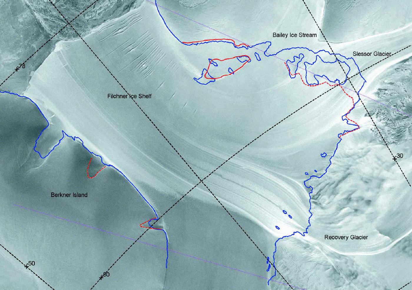
Fig. 3. The outer limits of the two RADARSATswaths are shown as a dotted magenta line superimposed on a background image from the AMM Antarctic Mosaic. The grounding line taken from Reference VaughanVaughan and others (1995) is shown in blue together with the current grounding-line estimates determined from SRI in red. A solid line indicates a 1–2 km mapping accuracy; a dashed line indicates that the interpretation is more difficult and the positional errors are unknown.

Fig. 4. Illustration of the proposed ice rise at the outflow of the Bailey Ice Stream; (a) SARamplitude image; (b) the coherence; (c) the interferometric phase; (d, e) the phase gradients in the along-track (vertical) and range (horizontal) directions, respectively; (f) ice elevation data which show a weak elevation signature supportive of the interpretation of this feature as an ice rise.
Summary
Interferometric SAR data from the 1997 RADARSATAMM have been used to provide new information on the grounding lines in parts of the eastern Ross Ice Shelf and the FIS. The method relies on identifying the regions of strong phase gradients that can occur in SAR interferograms of grounding-zone areas due to tidally induced height change.
The new grounding-line data immediately upstream of the CIR in the southeastern sector of the Ross Ice Shelf are consistent with the previous suggestion of increased grounding in this area. These results also show that a sub-ice water channel around the southern edge of the CIRis unlikely, although such a channel may have existed in the past. Results for the FIS also show some improvements to our knowledge of the grounding line. A large ice rise is mapped at the outflow of the Bailey Ice Stream into the FIS, while the existence of several previously mapped smaller grounded features is questioned.
Acknowledgements
RADARSATdata are copyright the Canadian Space Agency (CSA) and provided by RADARSAT International and the Alaska SAR Facility. The AMM data were collected as a result of a cooperative NASA/CSA project led by K. Jezek of the Byrd Polar Research Center (BPRC), The Ohio State University. Mission planning was carried out primarily by J. Crawford at the Jet Propulsion Laboratory (JPL), Pasadena. DEMs used in this work were provided by J. Bamber and K. Jezek. The background image used in Figures 2 and 3 is the 125 mmosaic produced by the BPRC. K.Mattar helped with software development and processing of some of the data used in this work. The ocean tidal modeling was supported by grants to Earth & Space Research from the U.S. National Science Foundation (NSF) Office of Polar Programs (OPP-9896041) and NASA (NAG5-7790). Work at NASA Goddard Space Flight Center was supported by NSF, while NASA supported the work at JPL. Helpful comments on the paper were provided by E. Rignot of JPL.


