1. Introduction
Crack growth and fracture of snow when a skier steps on a layered snowpack is studied using the finite-element method (FEM). In the past (Reference Bader and SalmBader and Salm, 1990), FEM has been used to investigate crack growth in the snowpack, and one of the present authors has used the implicit dynamic FEM to study crack propagation velocities for a crack existing at the interface between layers (Reference Mahajan and JoshiMahajan and Joshi, 2008). Here we make some modifications and additions to this earlier work, and study the mechanism of fracture when a skier steps on a layered snowpack.
The failure of snow stratification occurs by combined slope-parallel and slope-normal displacements. In the past, Reference McClungMcClung’s (1981) extension of Reference Palmer and RicePalmer and Rice’s (1973) theory on consolidated clays to snow has been widely accepted to describe fracture initiation in snow. Snow is a quasi-brittle material, and ahead of the crack tip a strain-softening damaged region exists. McClung’s approach involved putting a slip surface or shear band in the snow. The shear band had only a low residual stress, whereas the tip region of the band had a softening stress–displacement relation, with stress varying between the residual and a peak stress. Reference McClungMcClung (1981) studied the stress concentration ahead of the shear band and resulting shear failure initiation along the slope due to the component of weight along the slope. Slope-normal displacements were not considered in this model. Experiments on fracture speeds through a weak layer in snow on low-angled terrains by Reference Johnson, Jamieson and StewartJohnson and others (2004) showed a crack propagation speed of 20ms−1. Reference Van Herwijnen and JamiesonVan Herwijnen and Jamieson (2005) observed crushing of the weak layer due to fracture in the weak layer, and from the displacement of markers placed in the snow layer above the weak layers they determined crack velocity in snow in the range 17–26m s−1. One explanation for these low speeds was that the fracture involves slope-normal displacements of the snowpack containing a collapsible layer. It is possible that, for a snowpack on a slope, both mechanisms, i.e. the shear failure and slope-normal collapse, occur simultaneously. Reference Heierli and ZaiserHeierli and Zaiser (2008) assumed that the snowpack consisted of a superstratum, a weak interstratum and a substratum. The superstratum behaves as a beam and undergoes bending due to collapse of a certain length of the weak layer (a crack) of the interstratum. They included both the slope-parallel slip mechanism and slope-perpendicular collapse to study failure of snow. Their slope-parallel mechanism, however, does not include the interfacial failure. The failure of the interstratum in the combined mode is modeled by single fracture energy.
We study the crack growth and fracture of snow when a skier steps on an 8 m long snowpack. The snowpack is assumed to have three layers: two strong layers, in between which a weak layer is sandwiched (Fig. 1). The weak layer is assumed continuous throughout without an initial crack. The forces acting on the snow surface are components of the weight of the skier distributed over 0.2 m length of the slope (Reference Habermann, Schweizer and JamiesonHabermann and others, 2008). Two modes of failure in the snowpack are considered: (1) interfacial failure between the strong and the weak layer mainly due to shear at the interface, and (2) failure of the weak layer due to shear and compressive stresses within it. Since FEM is used, the axial and bending deformations (including transverse shear effects) modeled by Reference Heierli and ZaiserHeierli and Zaiser (2008) are included in modeling. The height of the snowpack is such that the initial failure in snow does not occur under the self-weight of the snow. First, the stresses in the snowpack under its self-weight alone are determined using static FEM. The snowpack is assumed to have lain long enough to reach an equilibrium state. Next, explicit dynamic FEM is used to determine additional stresses caused in the snowpack by the skier and the resulting failure of the snowpack. The analysis is performed assuming snow to be elastic, and creep of snow has not been included while determining the static deformation.
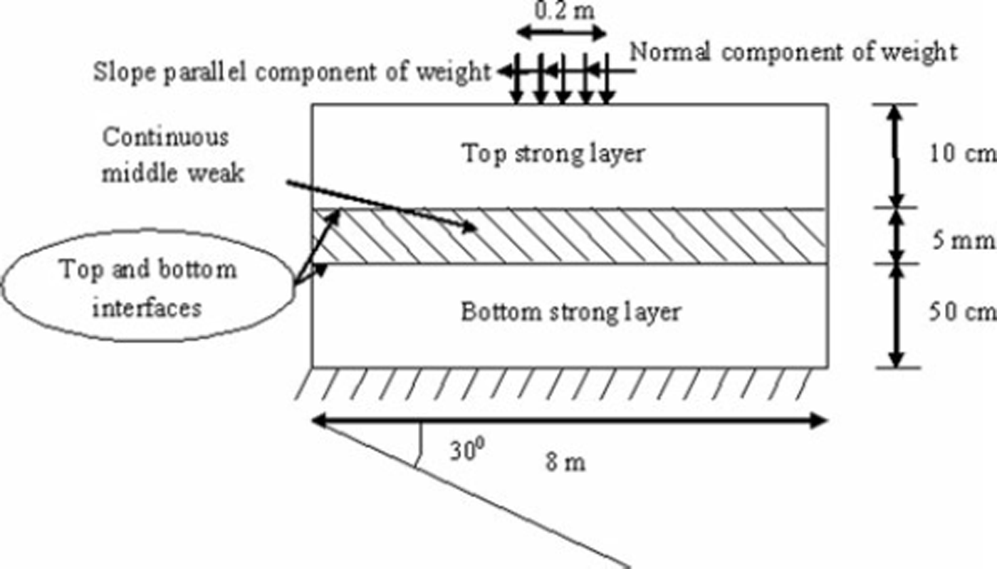
Fig. 1. Geometry of and load on snowpack on a slope. The weak layer is continuous with weak interfaces.
2. Interface and Weak-Layer Failure
The interface between layers is modeled using strain-softening cohesive elements characterized by fixed peak strength but zero residual strength (Fig. 2). The cohesive elements are therefore similar to the band tip region in Reference McClungMcClung (1981) except that they are more versatile, as it is possible to observe both initiation and propagation of the interface crack with these elements. The cohesive elements can also model interface failure due to tensile loading between the layers. After interface failure, the failed faces may remain in contact due to the compressive load acting normal to the slope, and slide with respect to each other. The friction between these faces is neglected in this study. The second mode of failure considered is failure of the weak middle layer due to compressive and shear stresses within it. In the absence of a suitable failure criterion for snow in the weak layer which takes multiaxial loading into consideration, it is assumed that failure initiates when the von Mises stress in the layer exceeds a limiting value. Once the failure has initiated, damage growth in the weak layer is modeled using a strain-softening curve relating the von Mises stress and displacement until final failure occurs. The area under this curve corresponds to the fracture energy required for this mode of failure. At present, to prevent interference between cohesive interface failure and elements of the weak layer next to the interface, this failure in the weak layer is restricted to a single layer of elements at the center of the weak layer. Once this layer of elements fails, surfaces on either side of it can come into contact and slide with respect to each other. Here a value of 0.6 is used for the coefficient of friction between these surfaces, although for snow interfaces it may vary between 0.57 and 0.84 (Reference Heierli and ZaiserHeierli and Zaiser, 2008).
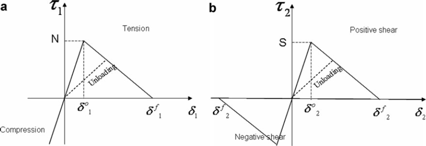
Fig. 2. Constitutive relations at the interface: (a) normal traction for pure mode I and (b) shear traction for pure mode II.
To determine the state of stress in the snowpack, the principle of virtual power for dynamics is
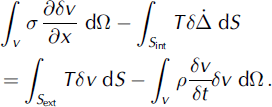
Here σ is the Cauchy stress, v is the velocity, Ω is the volume of the body, and ![]() is the virtual jump displacement across the cohesive element faces. S
ext and S
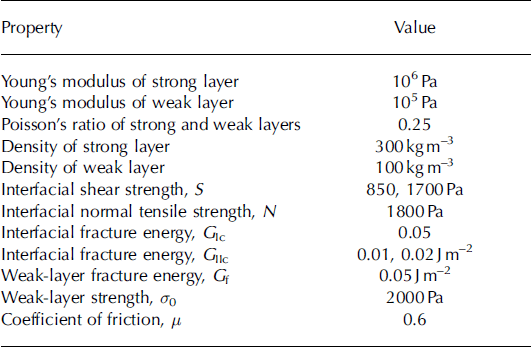
int are the external surface area and internal cohesive surface area of the body. The density of the material is p, and T is the traction vector. For statics, the second term on the right-hand side is zero. The layers are assumed to be isotropic elastic with two elastic constants E and v, the modulus of elasticity and Poisson’s ratio respectively. For all simulations E=1.0MPa for the strong layers, E = 0.1 MPa for the weak layer and ν= 0.23 for all layers. The densities of strong and weak layers are 300 and 100 kg m−3 respectively. These properties are listed in Table 1.
is the virtual jump displacement across the cohesive element faces. S
ext and S
int are the external surface area and internal cohesive surface area of the body. The density of the material is p, and T is the traction vector. For statics, the second term on the right-hand side is zero. The layers are assumed to be isotropic elastic with two elastic constants E and v, the modulus of elasticity and Poisson’s ratio respectively. For all simulations E=1.0MPa for the strong layers, E = 0.1 MPa for the weak layer and ν= 0.23 for all layers. The densities of strong and weak layers are 300 and 100 kg m−3 respectively. These properties are listed in Table 1.
Table 1. Properties used in simulations
2.1. Constitutive behavior of interface
Cohesive elements are zero thickness elements provided at the interface of layers to analyze the growth of a crack along the interface between two layers. Reference Mahajan and JoshiMahajan and Joshi (2008) used cohesive elements based on the formulation of Reference Xu and NeedlemanXu and Needleman (1994). A bilinear softening constitutive behavior of the cohesive zone model shown in Figure 2 is used in the present study (Reference Camanho and DávilaCamanho and Davila, 2002). This model is available in Reference Hibbitt, Karlsson and SorensenHibbitt and others (2005). In Figure 2, N is the interfacial normal tensile strength and S is the interfacial shear strength. Although the present constitutive model is different from the model used by Reference Mahajan and JoshiMahajan and Joshi (2008), it has been observed by the authors that the results are not much affected by the form of the constitutive law as long as the fracture energy remains the same (Reference Li and ChandraLi and Chandra, 2003).
The area under the traction-relative displacement curves is the respective (mode I or mode II) critical fracture energy required to cause failure (G
IC or G
IIC respectively) and ![]() and
and ![]() define the final relative displacements corresponding to complete normal and shear separation respectively as:
define the final relative displacements corresponding to complete normal and shear separation respectively as:
For snow, the strength and energy properties vary depending on the type of snow. Here G
IC = 0.05 J m−2, G
IIC
= 0.01 J m−2, N= 1800 Pa and S=850 Pa. These values are the same as used in Reference Mahajan and JoshiMahajan and Joshi (2008), which, as reported there, are close to the values reported by others (Reference Sigrist, Schweizer, Schindler and DualSigrist and others 2006; Reference McClungMcClung, 2007). From Equation (3), it can be seen that ![]() is approximately 2.35 × 10⁻⁵ m for snow, and fracture is supposed to have occurred if the nodes at the interface separate by this distance. Subsequent to interface failure, friction between crack faces has not been included in the present model.
is approximately 2.35 × 10⁻⁵ m for snow, and fracture is supposed to have occurred if the nodes at the interface separate by this distance. Subsequent to interface failure, friction between crack faces has not been included in the present model.
Equations (2) and (3) are used when loading is either pure tensile or pure shear. Under mixed-mode loading, the softening behavior may occur before any of the traction components reach their respective allowable values. Therefore, a quadratic failure criterion accounting for the effect of the interaction of the traction components in the onset of interface failure is used as given below:
Here τ 1 and τ2 are normal and shear tractions in the cohesive elements. To predict the interfacial crack propagation under the mixed-mode loading, the following criterion is used:
where G and GI are the fracture energies in normal and shear directions respectively; G IC and GIC are the critical fracture energy values in normal and shear directions.
2.2. Middle-layer failure criterion
In plane strain, the middle layer experiences σ 11, σ 33, σ 22 and σ 12. Only the last two have a significant numerical value. The initiation and propagation of failure in the middle layer occurs under this multiaxial stress state leading to slope-normal and parallel displacements. Here we initiated middle-layer failure when the von Mises stress exceeded 2000 Pa (Reference Jamieson and JohnstonJamieson and Johnston, 1997). Subsequent to initiation, damage occurs in the material, and the modulus of the material reduces. This reduction due to damage is often represented by a softening stress-displacement relation which is assumed to be linear (Fig. 3). The area under the equivalent stress-strain curve is the fracture energy of the material and is taken as 0.05 J m–2. The assumption of von Mises initiation and the use of an equivalent stress-strain relation is an approximation and can be improved upon in future. To remove mesh dependency due to strain softening, the equivalent failure strain εf 0 for an element is varied using
where the characteristic length L of the elements is calculated as ![]() for the two-dimensional case, a
0
is the von Mises stress, G
f is the energy to fracture and A is the area of the element. We have implemented the above ideas using the shear failure criterion approach available in Reference Hibbitt, Karlsson and SorensenHibbitt and others (2005). When restricted to a single row of middle elements (0.625 mm × 0.625 mm) of the weak layer as done here, this approach is similar to the smeared crack approach. The failed elements are eliminated from the mesh. Due to bending, it is possible that faces of elements on either side of this middle row of failed elements come into contact and slip with respect to each other. During this slip, μ = 0.6 has been used.
for the two-dimensional case, a
0
is the von Mises stress, G
f is the energy to fracture and A is the area of the element. We have implemented the above ideas using the shear failure criterion approach available in Reference Hibbitt, Karlsson and SorensenHibbitt and others (2005). When restricted to a single row of middle elements (0.625 mm × 0.625 mm) of the weak layer as done here, this approach is similar to the smeared crack approach. The failed elements are eliminated from the mesh. Due to bending, it is possible that faces of elements on either side of this middle row of failed elements come into contact and slip with respect to each other. During this slip, μ = 0.6 has been used.
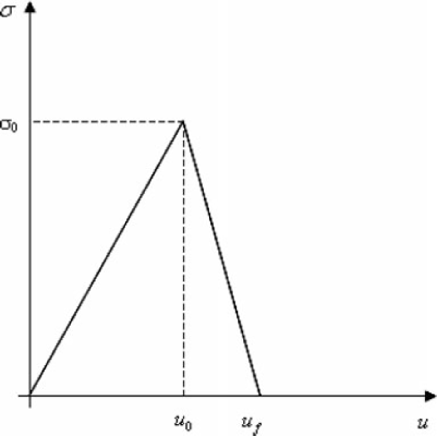
Fig. 3. Linear softening of weak layer of snow after failure initiation.
3. Snowpack Loading and Crack Growth Simulations
The initial load on the snowpack consists of the weight of snow. The deformations and stresses due to this are calculated using static FEM. Subsequently, once the skier steps on the snow, additional slope-normal compressive and shear forces due to the weight of the skier are assumed constant and uniformly distributed over 0.2 m length. Here we follow the work of Reference Habermann, Schweizer and JamiesonHabermann and others (2008) and Reference Heierli and ZaiserHeierli and Zaiser (2008) and assume no slip between the skier and the snow. The deformations and stresses are calculated by explicit dynamic analysis. To simplify the problem further, we do only a plane strain analysis (1 m wide) and assume the 8 m long snowpack consists of three layers, two strong layers, in between which a weak layer is sandwiched (Fig. 1). The weak layer is 5 mm thick and is located 50 cm from the ground. The bottom of the snowpack is assumed fixed to the ground. A weak interface occurs on both sides of the weak layer, and cohesive elements were placed at both the interfaces. The height of snow above the weak layer was 10 cm. This height was chosen so that snow failed only when the skier stepped on it. The snowpack is assumed to lie on a uniform slope of 30°, and the load on the snowpack was taken as the weight of the skier (750 N) uniformly distributed over an area of 0.2 m2 (plane strain 1 m wide). On the basis of convergence studies, performed earlier, the size of plane strain elements and cohesive elements was taken as 6.25 × 10⁻⁴ m. The time-step size was approximately 10−5s, and total time for the 8 m layer to fracture was 0.1–0.16 s. Contact elements were used at the interfaces to prevent penetration of the faces. They were also used between the layers of the middle surface on either side of the single row of elements of the middle layer which were allowed to fail as mentioned in section 2.2. Studies were performed for two different values of critical fracture energy (G IIc) of the interface: 0.01 and 0.02 J m−2. Since the critical fracture energy is given by the area under the stress-displacement curve, the fracture energy was doubled by doubling the fracture strength from 850 Pa to 1700 Pa. The study was conducted for a snowpack lying on a slope of 30° and also for a snowpack lying on flat ground. In these studies, no initial crack was introduced either at the interfaces or within the weak layer.
4. Results and Discussion
The snowpack failures for the two different fracture energies are shown in Figures 4 and 6. For G IIc = 0.01 J m−2, the middle layer and the interface failed simultaneously in the downslope region ahead of the skier (Fig. 4a). The interfacial crack propagates along the top and bottom interfaces in shear, accompanied by some bending of the elements above the failed middle region (Fig. 4b). These downslope interfacial cracks are longer than the failed weak middle layer. With time, the failure of the middle elements of the weak layer also grows upslope along with the interfacial failure in the upslope region. Upslope, initially the rates of middle-layer failure and interfacial failure are similar, but very soon (t=1.15 × 10⁻²s) here also the rate of failure of the middle layer becomes slower than the growth of interfacial cracks. Both down- and upslope, the interfacial cracks at the top and bottom interfaces grow simultaneously. In Reference Hibbitt, Karlsson and SorensenHibbitt and others (2005) the failed elements of the middle layer were deleted and elements initially on either side of it came into contact. At most locations, failure of the middle layer leads to slope-normal settlement of the layers above without interface opening (Fig. 4c). In some places, middle-layer failure may lead to interface opening besides sliding (Fig. 4d). As a result, the weak-layer elements above the failed elements may show local bending. Subsequently, however, the top strong layer settles down and closes this slope-normal interface opening. The final failure of the slab was by interface failures reaching the ends of the snowpack (Fig. 4e). During the time the interface cracks reached the ends (4 m on either side of the skier), the collapse of the middle layer travelled approximately 1.4 m on either side. Beyond 1.4 m the stresses in the middle-layer elements change with time but are always below the failure strength. The average up- and downslope interface crack velocities were 52 and 48ms−1, whereas the average velocity of the weak-layer failure and subsequent collapse was about 14ms−1. The variation of velocities for weak-layer failure and interface failure with failure length is shown in Figure 5. At the time of interface failure, the slope-parallel displacement of the snow below the skier was 1.25 cm. The maximum slope-perpendicular displacement was 2.2 mm.

Fig. 4. Various stages in failure of a snowpack with G IIc = 850Jm−2 and S= 850Nm−2. (a) Snowpack with G Ic = 0.01Jm−2. (b) The interfacial crack (in brown) and failure of middle elements (red) of weak layer appear almost at the same time. (c) Failure of middle elements of weak layer and bending of layers above it. The interface cracks grow. (d) Collapse of the weak layer (in red), interface growth (brown) and opening of interface normal to slope (blue). (e) Propagation of top and bottom interface cracks leading to snowpack failure.
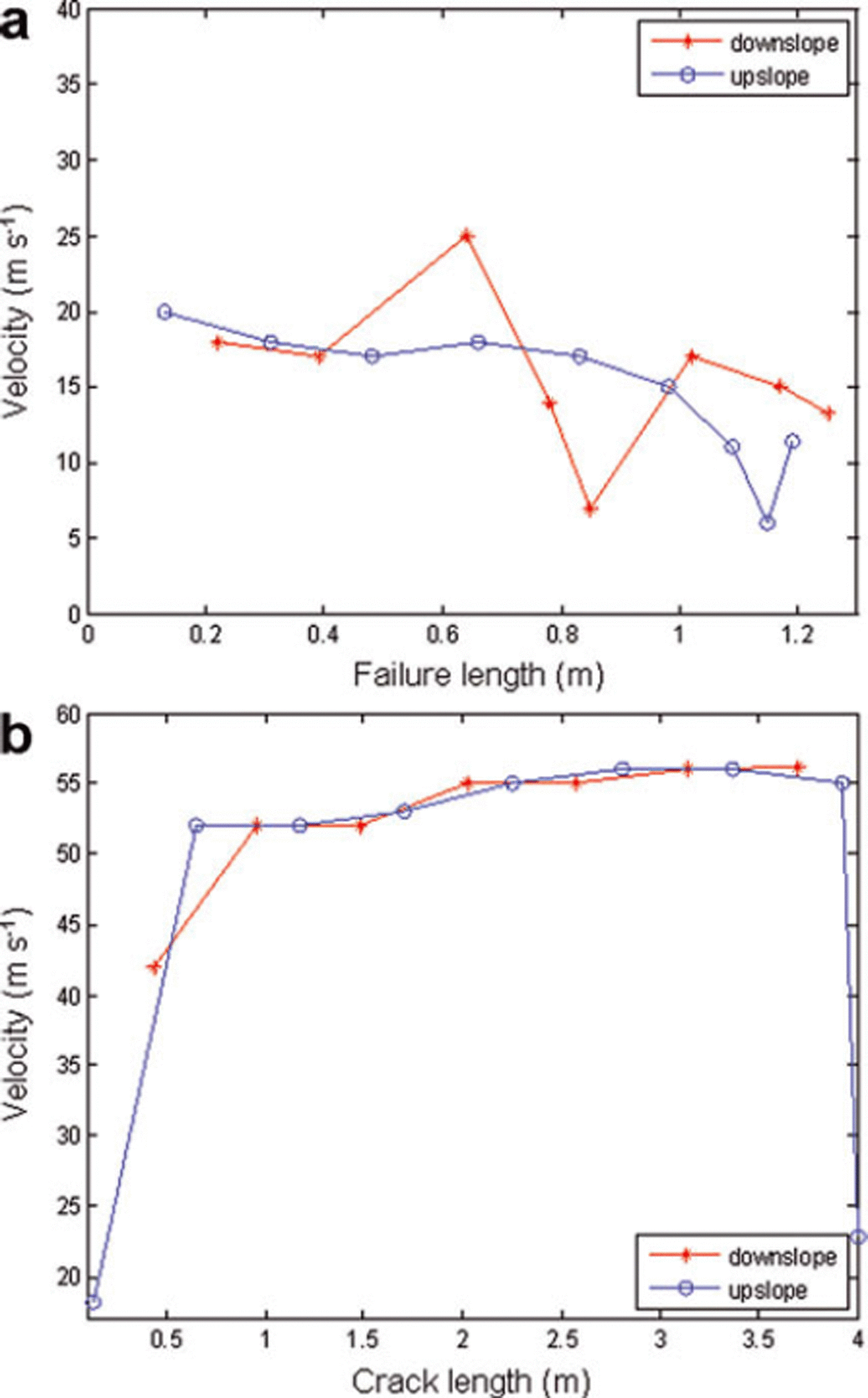
Fig. 5. Failure velocity versus failure length for S = 850 N m−2, GIIC = 0.01 J m−2. (a) Failure of weak layer; (b) failure of interface.

Fig. 6. Various stages in failure of a snowpack with an interface crack with interface shear strength = 1700Pa and G IIc = 0.02Jm−2. (a) Snowpack with G IIc = 0.02Jm−2. (b) The weak layer fails (red) and elements above it collapse. The interface crack (brown) is smaller than the failed weak layer. (c) Weak middle layer fails and interface cracks grow. Opening of interface normal to slope can be seen. (d) The local interface crack closes as layers above it deform. (e) Downslope, the interface cracks reach the boundary before the weak-layer failure reaches it. Upslope, both interface and weak-layer failure grow together at half the speed.
For snow lying on a flat slope, middle-layer failure and interfacial failure occur simultaneously. Since there is no slope-parallel shear it is most likely that middle-layer failure leads to bending of the slab after failure of the weak middle layer, which in turn causes interfacial failure. The failure extended to approximately 1.4 m on either side of the skier, giving an average velocity of 14 ms−1. The snow in the failed region experienced normal settlement. Subsequently, the velocities reduced, failure growth was very slow and simulations were stopped.
Middle-layer failure occurs first for a fracture energy G IIc of 0.02 J m−2. The downslope interface crack did not open until the weak-layer failure had reached 0.38 m from the skier (Fig. 6b). The layers above the failed layer deformed together, and touching of the layers on either side of the eliminated weak-layer elements was observed. At this stage, weak-layer elements which were no longer supported opened in mode I behind the failed (and eliminated) weak middle layer (Fig. 6c). From this time onward this local phenomenon was observed, although these interface cracks would close as the upper layers pressed on them (Fig. 6d). Until t=7x10⁻² s the interface cracks (top and bottom) were behind the weak-layer failure (approximately 1.6 m). From this time onwards, the interface cracks started to move ahead of the collapsed region, and final failure at t = 15.4 × 10⁻² s was due to interface failure. At the time of final failure, the collapsed region had spread to 3 m while the interface cracks had travelled the full 4m downslope (Fig. 6e). Around t = 8.5 × 10⁻²s we found that the downslope middle-layer failure was continuous until 1.78 m, but smaller discontinuous failed elements could be seen until 2.04m ahead of the continuous region. In the next time-step, these discontinuous regions merged with the continuous failed layer. At the same time, in the upslope region the middle-layer failure and interface crack growth occurred simultaneously and had grown by only 2.13 m. The average downslope weak-layer failure speed was 18 ms−1, whereas the average interface failure speed was 26 m s−1 (Fig. 7). The slope-parallel displacement at the time of failure was 3.2 mm (compared with 1.25 cm seen earlier for G IIc = 0.01 J m−2). Before the interface crack overtook middle-layer failure, this displacement was 1.9 mm. The maximum slope-normal displacement was 2.2 mm.
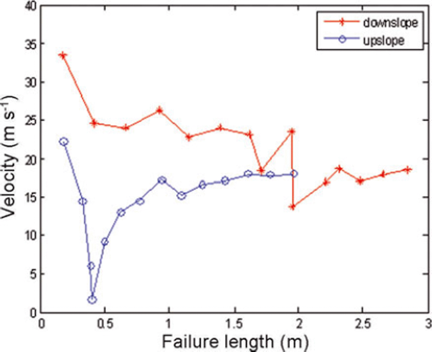
Fig. 7. Weak-layer failure velocity versus failure length for S=1700Nm−2, G IIC =0.02Jm−2.
It is difficult to compare the results of the present work with existing experimental data (Reference Van Herwijnen and JamiesonVan Herwijnen and Jamieson, 2008), as we have not exactly simulated the same experiments here. In the experiments, the weak-layer thickness was 3–9cm and slope-normal displacements were 0.5–4 cm. The slope-parallel displacements were smaller, 0.2–1.96 cm. Also, the elastic and fracture properties of snow used in these experiments are not fully available. The slope-parallel displacement of the node below the skier, when weak-layer failure was significant, was only 3.2 mm as compared to 1.25 cm when interface failure was active. In either case, slope-normal displacement below the skier was 2.2 mm. The FE model includes all the features available in the analytical model of Reference Heierli and ZaiserHeierli and Zaiser (2008). Also, interfacial failure not included in the above model is taken into consideration, which may be important for snowpacks with low strength and low interfacial fracture energy.
5. Conclusions
A snowpack, lying on a slope, is modeled as comprising three layers, with a weak layer in between two strong layers. No initial crack was introduced in the snowpack. The loads considered are the self-weight and the skier load, and failure propagation in the snowpack under these loads is investigated. The two possible failure mechanisms investigated are the growth of a shear crack along the interface between the layers and failure of the weak layer leading to slope-normal displacements of the snow above it. Cohesive elements are used to model interfacial crack propagation between layers. Failure of the weak layer is concentrated in a single row of elements, and a softening stress–displacement relation is used to describe it. For a fixed value of strength and fracture energy of the middle layer used here, the study showed that interfacial fracture strength and energy may decide how the fracture propagates. For low interfacial shear strength and fracture energy (G IIc = 0.01 J m−2) the interfacial fracture grows faster than the middle-layer failure, and the collapse or slope-normal displacements were limited to 1.4 m away from the skier. For higher interfacial fracture energy (G IIc = 0.02 Jm−2), snowpack failure was due to failure of the weak middle layer. The space left by middle-layer failure leads to significant bending of the top layer and slope-normal displacements. For higher values of interfacial strength, failure of the weak middle layer is the main failure mechanism and interfacial failure is a consequence of this. However, at some point interfacial failure overtakes middle-layer failure. For snow on flat ground, failure of the weak middle layer was mainly observed, though this seemed to slow down with time.
This paper improves on earlier work by including collapse and illustrates how snowpack failure can be studied using finite-element technique. The limitations, such as restricting collapse to one layer of elements, including friction for cohesive elements, and restricted height of the top strong layer so that fracture is initiated only due to additional skier load, can be improved upon. The determination of a suitable failure criterion under multiaxial loading and a post-initiation stress–displacement curve requires extensive experimental work.
Acknowledgements
We thank the scientific editor and an anonymous referee for their suggestions and meticulous revision of the paper.


