


1. Introduction
As per Archimedes’ principle, only objects with an average density smaller than the density of the water float at the air–water interface. However, even objects denser than the water float at the air–water interface in some cases. For example, small cylindrical metal pins, although denser than water, start floating when placed gently on the air–liquid interface. The floating ability of a metal pin is attributed to the surface tension force that acts on objects floating at the air–water interface (Keller Reference Keller1998; Mansfield, Sepangi & Eastwood Reference Mansfield, Sepangi and Eastwood1997). That is, besides the buoyancy force, the vertical component of surface tension supports the weight of the objects floating at the air–water interface. While the surface tension force acts on every object floating at the air–water interface, its influence on the floating ability of an object depends on the relative magnitude of the surface tension force in comparison with the buoyancy force. The relative strength of these forces is given by the Bond number, which is expressed as the ratio of buoyancy force to surface tension force. Mathematically, the bond number is given by  $\Delta \rho L^2 g/ \gamma$, where
  $\gamma$ is surface tension,
  $L$ is the length scale of the object,
  $g$ is the acceleration due to gravity and
  $\Delta \rho$ is difference between the densities of two fluids forming the interface. For small-scale objects, that is, objects with a length scale of the order of the capillary length or smaller, the magnitude of the surface tension force becomes comparable to the weight of the liquid displaced by the floating object (Vella Reference Vella2015). The capillary length is defined as the length scale of the body at which the surface tension force acting on the body is comparable to the weight of the liquid displaced by the body and is given by
  $(\gamma / \rho g)^{1/2}$. Due to this reason, stable orientations of small-scale floating bodies differ from large-scale floating objects of similar shape and geometry.
The ability of a floating body to regain its initial orientation after being disturbed is defined as the stability of the floating body. Various studies (Bhatnagar & Finn Reference Bhatnagar and Finn2006; Janssens, Chaurasia & Fried Reference Janssens, Chaurasia and Fried2017) have been carried out to investigate the stability of small-scale floating objects. For example, Janssens et al. (Reference Janssens, Chaurasia and Fried2017) investigated the net torque acting on a horizontally floating cylinder when subjected to a surface tension gradient. In this study, the liquid on one side of the horizontal cylinder was treated with surfactants while the liquid on the other side was kept surfactant free, thereby creating a surface tension gradient. In a different study, Bhatnagar & Finn (Reference Bhatnagar and Finn2006) investigated the equilibrium configuration of a horizontal cylinder of infinite length when subjected to a perturbation along the vertical direction. These studies are limited to the investigation of the vertical and rotational stability associated with infinite length cylinders with their longitudinal axis parallel to the liquid–fluid interface. There are no studies that investigate the effect of an angular perturbation about the lateral axis of the horizontal cylinder. Also, previous studies do not address the stability of a horizontal cylinder when perturbed about the lateral axis. In cases wherein the longitudinal axis of the finite-length floating cylinder is perpendicular to the fluid–liquid interface. For example, a coin (cylinder with an aspect ratio (length/diameter) < 1) floats with its longitudinal axis perpendicular to the water surface, as shown in figures 1(a) and 1(b). Interestingly, the coin continues to float with a vertical orientation when perturbed, for example, by small waves on the water surface. In contrast, a long, thin cylindrical metal pin floats on water with its longitudinal axis parallel to the surface and remains in the same orientation when disturbed, as shown in figure 1(c). These observations illustrate that certain orientations are more stable for small-scale objects than others. This article presents an initial stability analysis of a small-scale cylinder floating at an air–liquid interface. We mathematically investigate the stable orientations of small-scale cylindrical floating bodies. In particular, we identify at what aspect ratio a small-scale cylinder in a given orientation becomes unstable. The identification of stable orientations of small-scale objects finds applications in the formation and stability of small-scale floating rafts (Protière et al. Reference Protière, Josserand, Aristoff, Stone and Abkarian2017) and self-assembly of particles floating at a liquid–fluid interface (Aubry et al. Reference Aubry, Singh, Janjua and Nudurupati2008).

Figure 1. Images showing small-scale cylinders floating at the air–liquid interface. (a,b) A coin (cylinder with aspect ratio < 1) floating in the vertical orientation. (c) A cylindrical pin (aspect ratio > 1) floating with longitudinal axis parallel to the interface.
2. Static equilibrium
We follow the classical approach used in initial stability analysis (Biran & López-Pulido Reference Biran and López-Pulido2013) and first calculate the position of static equilibrium. Using the static equilibrium position, we calculate the moments of various forces acting on the floating body when the body is perturbed by a small angular displacement  $\beta$. In our investigation, we consider a hydrophobic cylinder of length
  $l$, radius
  $R$, density
  $\rho _s$ and uniform contact angle
  $\theta$. For our analysis, we make several simplifying assumptions that are regularly used while analysing floatation of small-scale floating objects (Singh & Joseph Reference Singh and Joseph2005; Liu, Feng & Wang Reference Liu, Feng and Wang2007; Gao & Feng Reference Gao and Feng2011). We assume the surface of the cylinder to be perfectly smooth (zero contact angle hysteresis) with a fixed solid–liquid contact angle (Singh & Joseph Reference Singh and Joseph2005; Liu et al. Reference Liu, Feng and Wang2007; Gao & Feng Reference Gao and Feng2011). Similar to the initial stability analysis (Biran & López-Pulido Reference Biran and López-Pulido2013) of large-scale floating bodies, we assume the liquid is inviscid and incompressible. The assumptions of a smooth surface and inviscid fluid ensure that the three-phase contact line (TPCL) can move up and down relative to the cylinder surface without any resistance. We also assume that the disturbing moment is applied very gradually, and the angular perturbation is so small that the inertial moments due to the inertia of fluid and floating cylinder can be neglected. This is because, in the presence of fluid inertia, the liquid displacement due to horizontal displacement of the cylinder surface will perturb the TPCL, leading to the generation of waves. The cylinder is floating at an air–liquid interface with the liquid having density
  $\rho _l$ and surface tension
  $\gamma$. As the density of air
  $\rho _a \ll \rho _l$, we neglect the density of air in our calculations. A small-scale cylindrical particle, when placed gently on the liquid–fluid interface, can float with its longitudinal axis either (i) perpendicular or (ii) parallel to the liquid–fluid interface.
2.1. Vertical cylinder
We first calculate the static equilibrium position of a small-scale cylindrical body floating with its axis perpendicular to the air–water interface. Static equilibrium refers to the state when there is no net force and torque acting on the body. In other words, the cylinder is statically floating at the air–liquid interface. Figure 2 shows the schematic of a small-scale cylinder floating in the vertical orientation at the air–liquid interface. Under the conditions of static equilibrium, the weight of the floating cylinder  $F_w = {\rm \pi}R^2 l \rho _s g$, is balanced by the sum of the buoyancy force
  $F_b = ({\rm \pi} R^2 h \rho _l g + {\rm \pi}R^2 h_c \rho _l g)$ and the vertical component of the surface tension force
  $F_{st} = 2{\rm \pi} R \gamma \sin (\phi )$, which is mathematically expressed as
 \begin{equation} {\rm \pi}R^2 l \rho_s g = {\rm \pi}R^2 h \rho_l g + {\rm \pi}R^2 h_c \rho_l g + 2{\rm \pi} R \gamma \sin(\phi), \end{equation}
where  $\phi$ denotes the angle of inclination of the surface tension force with respect to the horizontal at the TPCL,
  $h_c$ represents vertical deformation of the liquid–air interface from the undisturbed interface at the TPCL (see figure 2) and
  $h$ denotes the wetted length of the cylinder below the TPCL. The buoyancy force is equal to the weight of the liquid displaced by the floating body. The weight of the liquid displaced by a small-scale floating body is given by the generalised Archimedes principle (Mansfield et al. Reference Mansfield, Sepangi and Eastwood1997; Keller Reference Keller1998). As per the generalised Archimedes principle, the weight of the liquid displaced by the small-scale floating body is equal to the sum of the weight of the liquid displaced in the region ‘abcd’ and region ‘cdef’ shown in figures 2(a) and 2(c). The volume of liquid displaced in the region ‘abcd’ is equal to the volume of the cylinder, which would fill the volume bounded by the wetted surface of the body and circles ‘ab’ at the bottom and ‘cd’ at the top (cylindrical volume bounded by circles ‘ab’ at the bottom and ‘cd’ at the top). The volume of liquid displaced in the region ‘cdef’ is equal to the volume of the vertical cylinder passing through the TPCL ‘cd’ or the circumference of circle ‘cd’), and the original horizontal undisturbed free surface (surface bounded by circle ‘ef’). The region ‘gde’ shows the volume of liquid displaced by the curved air–liquid interface ‘gd’. The weight of the liquid displaced by the curved air–liquid interface ‘gd’ is equal to the vertical component of surface tension force acting along the TPCL. Rearranging (2.1) gives the wetted length
  $h$ of the cylinder as a function of
  $\rho _s$,
  $\rho _l$,
  $l$,
$l$,  $h_c$,
  $\gamma$ and
  $\phi$, which is expressed as
 \begin{equation} h = l\frac{\rho_s}{\rho_l} -h_c - \frac{2\gamma \sin(\phi)}{R \rho_l g}. \end{equation}
Figure 2. Schematic showing the orientation of a cylinder with its longitudinal axis perpendicular to the liquid surface (a) under static equilibrium and (b) under small angular displacement  $\beta$. (c) The three-dimensional projection of volume displaced by the small-scale floating cylinder as per the generalised Archimedes principle. (d) Comparison of TPCL before and after the perturbation of the small-scale floating cylinder. Here,
  $\gamma$ denotes the surface tension,
  $\phi$ represents the angle of inclination of the surface tension with respect to the horizontal and
  $\theta$ is the contact angle.
From figure 2, the inclination angle  $\phi = (\theta - {\rm \pi}/2)$. The vertical deformation of the air–liquid interface
  $h_c$ around the cylinder is obtained from the solution of the Young–Laplace equation. The Young–Laplace equation for an axisymmetric air–liquid interface is given by (Fowkes & Hood Reference Fowkes and Hood1998; Norbury, Sander & Scott Reference Norbury, Sander and Scott2005; Anderson, Bassom & Fowkes Reference Anderson, Bassom and Fowkes2006; Finn Reference Finn2012)
 \begin{equation} \gamma \left[\frac{{\rm d}^2 z/ {\rm d}r^2}{[1+ ({\rm d}z/ {\rm d}r)^2]^{3/2}} + \frac{{\rm d}z/ {\rm d}r}{r[1+ ({\rm d}z/ {\rm d}r)^2]^{3/2}} \right] = g(\rho_l - \rho_a)z , \end{equation}
where  $z$ and
  $r$ denote axial and radial coordinates, respectively, with the origin located at the point of intersection of the longitudinal axis (
 $z$) with the plane of the undisturbed interface, as shown in figure 2. We solve (2.3) numerically with boundary conditions
 \begin{equation} \frac{{\rm d}z}{{\rm d}r} = \tan \phi\ \text{at} \ r = R \quad \text{and}\quad \frac{{\rm d}z}{{\rm d}r} \rightarrow 0 \ \text{at} \ r \rightarrow \infty . \end{equation}
The solution of (2.3) gives the vertical position of the air–liquid interface  $z$ as a function of
  $r$, from which we obtain
  $h_c$ by substituting
  $r = R$. Using
  $h_c$ in (2.2) gives the wetted length
  $h$ of the cylinder. From
  $h$ and
  $h_c$ we obtain the position of the centre of buoyancy
  $d_{cob} = (h_c - h)/2$ with respect to the TPCL. In the case of small-scale floating cylinders, the centre of buoyancy is defined as the centre of mass of the fluid displaced by the floating cylinder. The volume of liquid displaced by the cylinder is equal to the volume of the cylinder in the region
  $abfe$, as shown in figure 2.
After obtaining the equilibrium position, we perturb the body by giving a small angular displacement  $\beta$. After that, we calculate the resulting net moment acting on the body due to the surface tension, buoyant and gravitational forces. In our approach, we calculate the restoring torque by taking moments of the forces about the centre of the TPCL. As we consider the cylinder surface to be perfectly smooth, the TPCL slides on the curved surface of the cylinder without pinning when we perturb the vertical cylinder with infinitesimal angular displacement
  $\beta$ (Singh & Joseph Reference Singh and Joseph2005; Liu et al. Reference Liu, Feng and Wang2007; Gao & Feng Reference Gao and Feng2011). Now, when the cylinder is tilted infinitesimally in the clockwise direction, the TPCL moves axially upwards in the right half and downwards in the left half relative to the cylinder surface, as shown in figure 2(b). The sliding of the TPCL in opposite directions relative to the lateral surface of the cylinder in the right and left halves of the cylinder changes the shape of the TPCL from circular (represented by length
  $dc$ in figure 2d) to slightly elliptical (represented by length
  $uv$ in figure 2d). Moreover, the slide of the TPCL results in an equal depth of the TPCL
  $h_c$ around the cylinder, keeping the TPCL planar. As shown in figures 2(b) and 2(d), the TPCL before perturbation (
 $dc$) is equal to the projection of the TPCL after perturbation (
 $uv$) on the plane inclined at an angle
  $\beta$, which gives
  $dc = uv \cos (\beta )$. For small
  $\beta$,
  $uv \simeq st$, which means that the shape and length can be assumed to remain constant after the vertical cylinder is perturbed by infinitesimally small angular deflection. The infinitesimally small angular displacement and the assumption of no contact line pinning means that the TPCL remains horizontal with the depth of the TPCL (
 $h_c$) remaining fixed. Therefore, we assume that the vertical force balance remains unaffected when the cylinder is given a small angular displacement.
As the contact angle is fixed, the inclination angle of the surface tension force with respect to horizontal  $\phi$ decreases in the right half of the cylinder and increases in the left half of the floating cylinder. The change in inclination angle varies from
  $\pm \beta$ at points on the contact line that are normal to the axis of angular displacement to zero at points parallel to the axis of angular disturbance. Figure 3 illustrates the variation of the inclination angle along the TPCL when the floating cylinder is perturbed by smaller angular displacement
  $\beta$. The inclination angle varies from
  $\phi -\beta$ at point
  $A$ in figure 3 to
  $\phi$ at point B along the TPCL in the anticlockwise direction. In the left half, the inclination angle varies from
  $\phi +\beta$ at point
  $C$ to
  $\phi$ at
  $B$ along TPCL in the clockwise direction. This asymmetry in the magnitude of vertical component of the surface tension force about the centre of the TPCL gives rise to an unbalanced moment (see Appendix) given by
 \begin{equation} m_s = 4{\int_0}^{{\rm \pi}/2} R \gamma b \beta \cos\phi \left(1 - \frac{2 \alpha}{\rm \pi}\right) {\rm d}\alpha = \frac{8R^2 \gamma \beta \cos \phi}{\rm \pi} = M_s \beta , \end{equation}
whereas the torque due to horizontal components of the surface tension force cancels out. The parameter  $b$ denote the perpendicular distance between the line of action of the vertical component of the surface tension force from the axis passing through centre of the TPCL and parallel to the axis of angular displacement. Similarly, the parameter
  $a$ denotes the perpendicular distance between the line of action of the vertical component of the surface tension force from the axis passing through the centre of the TPCL and normal to the axis of angular displacement.

Figure 3. Schematic showing the variation of the inclination angle  $\phi$ around the circumference of a vertical cylinder when it is given a small angular displacement
  $\beta$. Under the small angular displacement
  $\beta$ in the clockwise direction, the inclination angle
  $\phi$ increases from
  $\phi -\beta$ in the direction perpendicular to the angular displacement to
  $\phi$ in the direction of angular displacement.
From figure 2(b), we see that the vertical component of the surface tension force on the left side of the inclined cylinder increases due to the increase in the inclination angle, whereas on the right side it decreases due to the decrease in inclination angle. This difference in vertical components of the surface tension force on the left and right sides of the cylinder gives rise to a clockwise moment about the centre of the TPCL, thereby trying to increase the clockwise angular deflection  $\beta$. From the above analysis we can say that the surface tension force always generates a destabilising moment in the case of a vertical cylinder. The moment of weight of the body about the centre of TPCL is expressed as
 \begin{equation} m_g = {\rm \pi}R^2 l \rho_s g \beta d_{cg} = M_g \beta , \end{equation}
here,  $d_{cg} = (l/2 - h)$ is the vertical distance between the centre of gravity (CG) from the TPCL, as shown in figure 4. Lastly, the moment of the buoyancy force about the centre of the TPCL
 \begin{equation} m_b = {\rm \pi}R^2 \rho_l g (h + h_c) d_{b} = M_b \beta, \quad \text{where}, \ d_b = \left(d_{nb} + d_{cob}\right)\beta, \end{equation}
is the horizontal distance between the centre of buoyancy (CB) and the TPCL after the floating body is perturbed by small angular displacement  $\beta$ and
  $d_{cob}$ is the vertical distance between the CB and the TPCL before the floating body is disturbed. The distance
  $d_{nb} = {R^2}/[4(h_c + h)]$ is the distance of the new CB from the longitudinal axis of the tilted body and is given by the ratio of the area moment of inertia of the body area at the undisturbed interface (about an axis parallel to the interface) to the volume of liquid displaced by the body in the hatched area.

Figure 4. Schematic showing the distance of the CG and the CB of the floating body from the centre of the TPCL. The lengths  $d_{cg}$ and
  $d_{cob}$ denote the distance of the CG and the CB of the undisturbed body from the centre of the TPCL, respectively. Whereas
  $d_b$ denotes the distance between the CB of the tilted body from the centre of the TPCL.
2.2. Horizontal cylinder
Next, we investigate the stability of a small-scale floating cylinder with its axis parallel to the undisturbed air–liquid interface. Figure 5 shows a schematic of a horizontal cylinder floating at an air–liquid interface. As in § 2.1, we begin with the calculation of the position of static equilibrium and then perturb the system by giving a small angular displacement  $\beta$ about the lateral axis passing through the centroid of the floating body. Due to its circular geometry, the cylinder is infinitely stable for any angular disturbance about the longitudinal axis. However, the body may be statically unstable in the case of angular disturbance about the lateral axis, as shown in figure 5. Under a static equilibrium condition, the balance of forces acting on the cylinder is given by
 \begin{equation} F_w = F_s + F_b, \end{equation}
where  $F_w = {\rm \pi}R^2 l \rho _s g$ is the weight of the floating cylinder
 \begin{equation} F_{st} = 2l\gamma \sin(\phi) + 4 R \gamma \sin(\phi_1)\sin(\psi), \end{equation}
is the vertical component of the surface tension force and  $F_b = R^2 l \rho _l g [2(h_c/R) \sin (\psi ) + \psi - \cos (\psi )\sin (\psi )]$ is the buoyancy force. In (2.9),
  $\phi$ is the inclination angle of the interface with respect to the horizontal along the lateral surface of the cylinder and
  $\phi _1$ is the angle of inclination of the interface at the two flat ends of the horizontal cylinder. Note that the angle of inclination of the air–liquid interface at the contact line is different at the flat ends from the inclination angle along the lateral surface of the horizontal cylinder. Due to the difference in the curvature of the surface at the contact point, the inclination angle at the flat ends is given by
  $\phi _1 = \theta - {\rm \pi}/2$ (see figure 5b) whereas
  $\phi = \psi + \theta - {\rm \pi}$ (see figure 5c).

Figure 5. Schematic showing equilibrium configuration of a cylinder floating with its longitudinal axis parallel to the undisturbed interface. The angle  $\phi$ denotes the inclination angle along the lateral surface, and
  $\phi _1$ denotes the inclination angle at two ends of the horizontal cylinder. The inclination angle at the two flat ends of the horizontal cylinder is given by
  $\phi _1 = \theta - {\rm \pi}/2$ whereas
  $\phi = \psi + \theta - {\rm \pi}$.
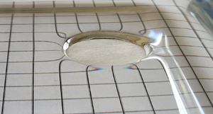
Figure 6 shows a horizontal cylinder made of aluminium with  $D = 2$ mm and
  $\theta = 152^\circ$ floating at an air–water interface in horizontal orientation. Figure 6(b) shows that the depth at which the curved air–water interface along the longitudinal axis meets the cylinder surface (curved edges of the dark semi-circle) is equal to the depth of the TPCL along the flat end (upper edge of the dark semi-circle) of the horizontal cylinder. Therefore, as shown in figure 5, in our analysis, we take the depth of the TPCL on the flat ends to be equal to the depth of the TPCL (
 $h_c$) along the lateral surface of the horizontally floating cylinder. As shown in figure 5(c),
  $\psi$ is the angle between the radial line joining the centre of the cylinder with the TPCL and the vertical. Using expressions of
  $F_w$,
  $F_b$ and
  $F_{st}$ in (2.8) gives
 \begin{align} {\rm \pi}R^2 l \rho_s g &= 2l \gamma \sin(\phi) + 4R \gamma \sin(\phi_1) \sin(\psi) \nonumber\\ &\quad + R^2 l \rho_l g [2(h_c/R) \sin(\psi) + \psi - \cos(\psi)\sin(\psi)] . \end{align}
Figure 6. Small-scale aluminium cylinder with  $D = 2$ mm and
  $\theta = 152^\circ$ floating at the air–liquid interface in horizontal orientation. (a) The top view of the horizontal cylinder shows the curved air–liquid interface around the contact line. (b) Front view of the horizontal cylinder showing the curved air–liquid along the lateral surface of the solid cylinder (dark semi-circle) at the same depth below the undisturbed interface as the TPCL on the flat end (dark edge of semi-circle parallel to horizontal direction) of the horizontal cylinder. The TPCL along the flat end appears to be bent upwards due to the refraction of light by the curved air–liquid interface. The image in (b) appears slightly blurred at the edges of the floating body and air–water interface due to high magnification and enlargement.
Expressing  $\psi$ in terms of
  $\phi$, we eliminate
  $\psi$ from (2.10). The resulting equation has two unknowns
  $\phi$ and
  $h_c$. The distance of the TPCL from the undisturbed interface
  $h_c$ is obtained by solving the Young–Laplace equation. For simplicity, we assume that the deformation of the liquid–fluid interface is a function
  $z = z(r)$ and solve the two-dimensional approximation of the Young–Laplace equation given by (Vella, Lee & Kim Reference Vella, Lee and Kim2006)
 \begin{equation} g\rho_l z = \gamma \frac{{\rm d}^2z/{\rm d}r^2}{[1+ ({\rm d}z/ {\rm d}r)^2]^{3/2}}, \end{equation}
to obtain  $h_c$. Equation (2.11) is solved analytically using (2.4) as boundary conditions, which gives,
  $h_c = 2 l_c \sin (\phi /2)$, where
  $l_c = [\gamma /(\rho _l g)]^{1/2}$ is the capillary length. Using
  $h_c$ in (2.10) and then solving for
  $\phi$ gives the inclination angle at the TPCL under a static equilibrium condition. We note that (2.10) is a transcendental equation having no explicit solution and therefore we solve it numerically. From
  $\phi$, we obtain
  $\psi = \phi - \theta + {\rm \pi}$. Using
  $\phi$ and
  $\psi$ we obtain the distance of the CB from the CG as
 \begin{equation} C_b = \frac{(2/3) R^3 \sin^3(\psi) + R \sin(\psi)(d_{cg}^2 - h_o^2)}{R^2(\psi - \sin(\psi) \cos(\psi))+ 2R\sin(\psi)h_c}, \end{equation}
where  $d_{cg} = R \cos (\psi )$ is the distance of the CG from the TPCL and
  $h_o = d_{cg} - h_c$ is the distance of the CG from the undisturbed interface.
Next, we disturb the static equilibrium by introducing a small angular displacement  $\beta$ about the lateral axis and then calculate the resulting moments acting on the floating cylinder. We calculate the moments of various forces about the lateral axis passing through the centre of the TPCL and lying in the plane TPCL. As the contact angle is fixed, a small angular perturbation leads to a change in inclination angle at the TPCL along the lateral and the two circular base surfaces of the cylinder. A small angular deflection about the transverse axis in the clockwise direction causes
  $\psi$ to change along the axial direction, as shown in figure 7. The circular profile of the lateral surface of the cylinder ensures that
  $\phi = \psi + \theta - {\rm \pi}$. Therefore, any increase in
  $\psi$ leads to an increase in
  $\phi$, which in turn leads to a change in the vertical component of the surface tension force along the axial length of the cylinder. This axial variation in the vertical component of the surface tension force gives rise to an unbalanced torque given by
 \begin{equation} m_{sl} = 4{\int_0}^{l/2} \gamma \beta \cos\phi \frac{x^2}{(R^2-{d_{cg}}^2)^{1/2}} {{\rm d}x} = \frac{4 \gamma \cos(\phi)}{3 (R^2 - {d_{cg}}^2)^{1/2}} \frac{l^3}{8} \beta . \end{equation}
Figure 7. Schematic showing variation of inclination angle  $\phi$ along the length of a horizontal cylinder under a small clockwise angular displacement
  $\beta$. As the contact angle is fixed, any variation in
  $\psi$ leads to change in
  $\phi$. In the above case, the inclination angle increases from left to right along the line
  $ab$.
$ab$.
Besides changing the inclination angle along the lateral surface, the angular deflection about the transverse axis also changes (i)  $\phi$ at the TPCL and (ii) the length of the TPCL along the flat base surfaces at the two ends of the horizontal cylinder. As shown in figure 7, a clockwise angular deflection leads to an increase in the length of the TPCL at one end and a decrease in the length at the other. Similarly, a clockwise angular deflection results in an increase in the inclination angle on the left base and a reduction in
  $\phi$ along the right base of the horizontal cylinder. The net moment due to the change in the length of the TPCL and
  $\phi$ along the two bases of the cylinder is given by
 \begin{equation} m_{sb} = \gamma l \beta \left(\frac{hl}{R \sin(\psi)} \sin(\phi) + 2R \sin(\psi) \cos(\phi)\right). \end{equation}
The net moment on the tilted horizontal cylinder due to the vertical component of the surface tension force is given by
 \begin{equation} m_s = m_{sb} + m_{sl} = M_s \beta. \end{equation}
The direction of the net torque generated by the surface tension force acting on the horizontal cylinder depends on the magnitude and direction of  $m_{sb}$ and
  $m_{sl}$. The direction of moment
  $m_{sl}$ is governed by the value of
  $\phi$ before the body is perturbed by the small angular displacement. For example, if initially
  $\phi < 90$, then any increase in
  $\psi$ (and therefore in
  $\phi$) due to clockwise angular perturbation results in an increase in the vertical component of the surface tension along the longitudinal axis on the right side of the floating cylinder. In contrast, the vertical component of the surface tension decreases along the length, which is on the left side of the centre of the cylinder. As a result,
  $m_{sl}$ acts in an anticlockwise direction, thus acting as a restoring torque. The moment due to the surface tension force acting along the flat ends of cylinder
  $m_{sb}$ always acts as a destabilising moment. This is because a small angular displacement in the clockwise direction decreases the inclination angle from
  $\phi _1$ to
  $\phi _1 - \beta$ along the TPCL on the right base of the horizontal cylinder, as shown in figure 7(b). In contrast, the inclination angle increases from
  $\phi _1$ to
  $\phi _1 + \beta$ along the TPCL on the left base of the horizontal cylinder, as shown in figure 7(b). Due to this difference in inclination angles, the vertical component of the surface tension force increases on the left base and decreases on the right base, resulting in a moment in the clockwise direction. Equations (2.13) and (2.14) show
  $m_{sb}$ and
  $m_{sl}$ respectively have quadratic and cubic dependences on
  $l$. Therefore, at small cylinder lengths
  $m_{sl} < m_{sb}$, whereas at large lengths
  $m_{sl} > m_{sb}$. As a result, in the case of a short horizontal cylinder (at small aspect ratios), the surface tension force generates a destabilising torque
  $M_s$. Whereas, in the case of a long cylinder (cylinder with a large aspect ratio), the moment due to the surface tension has a stabilising effect. The moment due to the weight of the cylinder about the centre of the TPCL is given by
 \begin{equation} m_g = {\rm \pi}R^2 l \rho_s g d_{cg} \beta = M_g \beta. \end{equation}
Lastly, the moment of the buoyancy force about the centre of the TPCL is expressed as
 \begin{equation} m_b = \left[ R^2 \left( \psi - \sin(\psi) \cos(\psi)\right) + 2R \sin(\psi) h_c\right] \rho_l g l d_b = M_b \beta, \end{equation}
where
 \begin{equation} \begin{array}{@{}c@{}}\displaystyle
d_b = \left(
d_{cob} + d_{nb} \right) \beta, \quad d_{nb} = \frac{l^2
\sin(\psi)}{R\left( \psi - \sin(\psi)\cos(\psi)\right) + 2
\sin(\psi)h_c} \quad \text{and} \\ \displaystyle d_{cob} = d_{cg} -
C_b .\end{array}
\end{equation}
\begin{equation} \begin{array}{@{}c@{}}\displaystyle
d_b = \left(
d_{cob} + d_{nb} \right) \beta, \quad d_{nb} = \frac{l^2
\sin(\psi)}{R\left( \psi - \sin(\psi)\cos(\psi)\right) + 2
\sin(\psi)h_c} \quad \text{and} \\ \displaystyle d_{cob} = d_{cg} -
C_b .\end{array}
\end{equation}
The net moment acting on the cylinder  $M_n = (M_s + M_b + M_g) \beta$. A cylinder is stable in the vertical or horizontal orientation if
  $M_n > 0$, which simplifies to
 \begin{equation} (M_s + M_b + M_g) \beta > 0. \end{equation}
As  $\beta > 0$, (2.19) can be further simplified by dividing the equation by
  $\beta$ to give
 \begin{equation} (M_s + M_b + M_g) > 0. \end{equation}
We non-dimensionalise the last equation by dividing the equation by  $\gamma l_c^2$, which gives
  $M = (M_s + M_b + M_g)/ \gamma l_c^2$. The cylinder is in stable equilibrium if
  $M>0$. Here, we note that there are two approaches, (i) balance of forces and (ii) variational approach (energy analysis) (Burton & Bush Reference Burton and Bush2012), to obtain the equilibrium configuration of the floating body. In this article, we have used the balance of forces approach to obtain (2.1) and (2.20). In the variational approach (energy analysis), we strive to obtain a configuration of the floating body that minimises the system's total energy. Regardless of the approach, we obtain identical equations ((2.1) and (2.20)) for the floating body system.
We next give a criterion to classify a cylinder with a density higher than water and floating at the air–water interface as a large-scale or small-scale cylinder. For a cylinder floating at the air–liquid interface, the weight of the cylinder  $F_g$ is balanced by the sum of the buoyancy force
  $F_B$ and the surface tension force
  $F_S$. For a cylinder in a horizontal orientation,
  $F_g = {\rm \pi}r_{ch}^2 l \rho _s g$,
  $F_s \approx \gamma l$ (
 $l > r$) and
  $F_B \approx {\rm \pi}r_{ch}^2 l \rho _l g$. Here,
  $r_{ch}$ is the characteristic radius of the cylinder. Under the condition of static equilibrium
 $$\begin{gather} F_g \approx F_S + F_B, \end{gather}$$
 $$\begin{gather}{\rm \pi} r_{ch}^2 l \rho_s g \approx \gamma l + {\rm \pi}r_{ch}^2 l \rho_l g, \end{gather}$$
 $$\begin{gather}r_{ch} \approx \sqrt{\frac{\gamma}{(\rho_s - \rho_l)g}}. \end{gather}$$
A cylinder in horizontal orientation can be classified as small scale if the radius of the cylinder  $r \approx r_c$ or smaller. Now, for a cylinder in vertical orientation
  $F_S \approx \gamma r_{ch}$.
A similar balance of forces acting on a vertical cylinder gives
 \begin{equation} r_{cv} \approx \frac{\gamma}{l(\rho_s - \rho_l)g}. \end{equation}
Like a horizontal cylinder, a cylinder in the vertical orientation can be classified as a small-scale cylinder if the radius of the cylinder  $r \approx r_{cv}$ or smaller. Equation (2.24) shows that
  $r_{cv}$ is inversely proportional to the length and density of the cylinder. This means that the larger the radius the smaller would be the length of the vertical cylinder that can float at the air–water interface. Similarly, the higher the density of the vertical cylinder the smaller would be the thickness at which the cylinder will float at the air–water interface.
3. Results and discussion
We begin by analysing the stability of the vertical cylinder floating at an air–water interface at various aspect ratios. Unlike large-scale cylinders, the stability of a small-scale floating cylinder not only depends on the aspect ratio but also on the absolute value of the radius of the cylinder. This is because the surface tension force varies linearly with the radius of the cylinder whereas the weight of the cylinder varies as the square of the radius, as shown in (2.1). Consequently, for a fixed length, as the radius of the cylinder increases, the proportion of the surface tension force in the upward thrust supporting the body's weight diminishes rapidly, which in turn breaks the static equilibrium. Therefore, we investigate the stability of the vertical cylinders with two different diameters,  $D = 15$ mm and
  $D = 1.5$ mm. Figure 8 shows the variation of non-dimensional moment
  $M$ with aspect ratio
  $l/D$ for vertical cylinders with solid–liquid contact angle
  $\theta = 150^\circ$,
  $\rho _s = 4000\ {\rm kg}\ {\rm m}^{-3}$, floating on a liquid with
  $\gamma = 0.0715\ {\rm N}\ {\rm m}^{-1}$ and
  $\rho _l = 1000\ {\rm kg}\ {\rm m}^{-3}$.

Figure 8. Net moment  $M$ acting on the vertical cylinder with contact angle
  $\theta = 150^\circ$ and density
  $\rho _s = 4000\ {\rm kg}\ {\rm m}^{-3}$ floating at an air–water interface at various aspect ratios. (a) Vertical cylinder with
  $D = 15$ mm. (b) Vertical cylinder with
  $D = 1.5$ mm. Net moment
  $M > 0$ shows that the cylinder is in stable equilibrium.
The cylinder with  $D = 15$ mm is in static equilibrium only below the aspect ratio of 0.095. Beyond the aspect ratio of 0.095, the vertical cylinder with
  $D = 15$ mm is not able to attain static equilibrium and therefore sinks. In other words, the cylinder with
  $D = 15$ mm is not able to float on the air–liquid interface at
  $l/D > 0.095$. In figure 8(a), we show the stability of the vertical cylinder only above the aspect ratio of 0.074. This is because, at
  $l/D \leq 0.074$, the wetted length
  $h=0$ for a vertical cylinder with
  $D = 15$ mm. In other words, the TPCL coincides with the sharp edge of the lower base of the cylinder. At the sharp edges, the contact angle is not defined by the Young–Dupre law and changes with the weight of the cylinder (
 $\theta$ decreases with the weight of the cylinder) (Singh & Joseph Reference Singh and Joseph2005; Burton & Bush Reference Burton and Bush2012). As the wetting condition at the sharp edge is unknown, the slope of air–liquid interface
  $\phi$ at the TPCL that forms the first boundary condition (see (2.4)) also becomes an unknown. Consequently, the Young–Laplace (2.3) cannot be solved to obtain
  $h_c$. Therefore, we have shown the stability of the vertical cylinder for those lengths for which contact angle can be predicted by the Young–Dupre law.
Such small aspect ratios for a cylinder floating in vertical orientation are expected because the maximum weight of the vertical cylinder ( $\rho _s > \rho _l$) of given diameter
  $D$ that the surface tension and buoyancy forces can support is fixed. As the mass is distributed to a large extent in the radial direction, there is a very small value of the thickness at which the vertical cylinder can attain static equilibrium. Importantly, from figure 8(a), we see that the vertical cylinder is stable at all the aspect ratios within the range
  $0.074 < l/D < 0.095$. Moreover, the stability of the cylinder increases with an increase in aspect ratio. The stability of the cylinder with
  $D = 15$ mm in vertical orientation can be attributed to the larger distance of the CB from the TPCL compared with the distance of the CG from the TPCL. Figure 9 shows a schematic that illustrates the relative locations of the CB and CG of a vertical cylinder floating at the air–water interface. The distance of the CB from the TPCL is larger because the volume of liquid displaced in the region cdef (see figure 9a) that lies outside the body is larger than the volume of liquid displaced in the region abcd, which is nothing but the volume of the floating body. The CB of the floating cylinder lies at the centroid of abfe, whereas the CG lies at the centroid of abcd, which clearly shows the larger distance of the CB from the TPCL compared with the distance of the CG from the TPCL. As a result, the anticlockwise moment created by the buoyancy force more than balances the destabilising moments created by surface tension and weight of the body. In cases wherein the TPCL lies above the CG, the body's weight creates an anticlockwise moment, thereby creating a stabilising effect.

Figure 9. Schematic showing the relative positions of the CG, CB and TPCL at different aspect ratios. (a) Vertical cylinder with  $D = 15$ mm. (b) Vertical cylinder with
  $D = 1.5$ mm.
Next, we analyse the stability of the vertical cylinder with  $D = 1.5$ mm floating at the air–water interface. Figure 8(b) shows the stability of a vertical cylinder with
  $D = 1.5$ mm at aspect ratios ranging between
  $l/D = 3.1$ and
  $4.1$. Like the cylinder with
  $D = 15$ mm, the vertical cylinder with
  $D = 1.5$ mm is in static equilibrium at
  $l/D \leq 3.1$. However, the TPCL coincides with the edge of the lower base of the cylinder at
  $l/D \leq 3.1$. Therefore, we limit our analysis to
  $l/D > 3.1$. However, before we discuss the stability of a floating vertical cylinder, we first describe what happens when the length of the cylinder is increased while keeping the radius constant. As the radius and contact angle of the cylinder is fixed, the vertical component of surface tension remains constant. For the vertical cylinder to remain in static equilibrium, a unit increase in length (
 $\Delta l$) is accompanied by an increase in wetted length of the cylinder (
 $h$ in figure 2) in the ratio of
  $\rho _s : \rho _l$. That is, the increase in wetted length
  $\Delta h = (\rho _s / \rho _l) \Delta l$. The increase in wetted length causes the vertical cylinder to settle lower into the liquid, which leads to a fall in the vertical position of the CG and CB, as shown in figure 9(b). As the CG and CB are located at the centroid of the volume of the body and the volume of liquid displaced by the body, respectively, the downward displacement of the CG is more than the downward displacement of CB.
Figure 8(b) shows that the stability of the vertical cylinder with  $D = 1.5$ mm increases with an increase in aspect ratio. However, unlike the vertical cylinder with
  $D = 15$ mm, the cylinder with
  $D = 1.5$ mm is in stable equilibrium only above the aspect ratio
  $l/D = 3.6$. Figure 10 shows the variation of moments of the three forces with the aspect ratio of the vertical cylinder. The plot shows that
  $M_g$ has a positive slope,
  $M_b$ has a negative slope and
  $M_s$ remains constant with increase in aspect ratio. At small aspect ratios, the CG and CB of the floating body lie above the TPCL. In the case wherein the CG and CB are above the TPCL, the weight of the cylinder generates a destabilising moment, whereas the moment due to buoyancy force has a stabilising effect. This is evident from
  $M_b > 0$ and
  $M_g < 0$ (see figure 10) at small aspect ratios of the vertical cylinder.

Figure 10. Variation of non-dimensional moments due to surface tension ( $M_s$), gravity (
 $M_g$) and buoyancy (
 $M_b$) forces with aspect ratio acting on a vertical cylinder with
  $\theta = 150^\circ$,
  $D = 1.5$ mm and
  $\rho _s = 4000\ {\rm kg}\ {\rm m}^{-3}$ floating at an air–water interface at various aspect ratios.
As discussed above, with an increase in the cylinder's length, the CG and CB slide down the vertical axis, with the CG dropping more than the CB. Due to this difference in downward displacement, there is larger reduction in  $d_{cg}$ compared with
  $d_b$, resulting in a larger reduction in the magnitude (absolute value) of
  $M_g$ in comparison with
  $M_b$. This larger reduction in the magnitude of
  $M_g$ than
  $M_b$ is apparent from the larger slope of
  $M_g$ than
  $M_b$ in figure 10. As the weight of the cylinder generates a destabilising moment for the case when the CG is above the TPCL, a larger reduction in the magnitude of
  $M_g$ increases the body's stability. Hence, the stability of the vertical cylinder with
  $D = 1.5$ mm rises with an increase in the aspect ratio. When the CG and CB fall below the TPCL, the body's weight generates stabilising torque, whereas the buoyancy force gives rise to the destabilising moment. The CB and CG fall below the TPCL corresponding to aspect ratios at which
  $M_b = 0$ and
  $M_g = 0$, respectively. The stabilising effect of the body's weight and destabilising action of the buoyancy force are evident from positive and negative values of
  $M_g$ and
  $M_b$ respectively at
  $l/D > 3.5$.
Next, we analyse the effect of the contact angle and density on the stability of a vertical cylinder. Figures 11(a) and 11(b) show the variation of non-dimensional moment  $M$ with aspect ratio
  $l/D$ for vertical cylinders with
  $D = 15$ mm, solid–liquid contact angle
  $\theta = 120^\circ$, but having
  $\rho _s = 4000\ {\rm kg}\ {\rm m}^{-3}$ and
  $\rho _s = 3000\ {\rm kg}\ {\rm m}^{-3}$, respectively. The plots show that the variation of the net moment with aspect ratio follows the same trend as we observe in vertical cylinders with
  $\theta = 150^\circ$. However, the maximum aspect ratio at which the vertical cylinder is in static equilibrium is lower for
  $\theta = 120^\circ$ than for the vertical cylinder with
  $\theta = 150^\circ$. Likewise, the stability of the cylinder with
  $\theta = 120^\circ$, which we characterise by the magnitude of net moment
  $M$ at the highest aspect ratio, is also lower than the cylinder with
  $\theta = 150^\circ$. These lower values can be attributed to the reduction in inclination angle
  $\phi$. As the inclination angle
  $\phi = \theta - {\rm \pi}/2$, the reduction in contact angle reduces the vertical component of the surface tension and depth of the TPCL
  $h_c$ below the undisturbed air–water interface. This, in turn, reduces the maximum weight of the cylinder of a given radius that can float at the air–liquid interface and therefore results in a lower maximum aspect ratio. The reduction in
  $h_c$ leads to a decrease in the distance between the CB and TPCL
  $d_{cob}$, resulting in a lower restoring torque compared with the cylinder with
  $\theta = 150^\circ$. Therefore, a reduction in contact angle lowers the stability of the cylinder floating in the vertical orientation. In contrast, a reduction in the density of a vertically floating cylinder increases the stability and maximum aspect ratio at which the cylinder attains static equilibrium. The increase in the maximum aspect ratio and stability is expected as lower density means the surface tension and buoyancy forces can support a larger length (thus higher aspect ratio) of a cylinder with a given radius
  $r$. The variation of moment
  $M$ with aspect ratio in the cylinder with
  $\rho _s = 3000\ {\rm kg}\ {\rm m}^{-3}$ follows the same trend as we see in the cylinder with
  $\rho _s = 4000\ {\rm kg}\ {\rm m}^{-3}$.

Figure 11. Net moment  $M$ acting on the vertical cylinder with contact angle
  $\theta = 120^\circ$ and
  $D = 15$ mm floating at an air–water interface. (a) Vertical cylinder with density
  $\rho _s = 4000\ {\rm kg}\ {\rm m}^{-3}$ and (b) with
  $\rho _s = 3000\ {\rm kg}\ {\rm m}^{-3}$.
We have now discussed the stability of the vertical cylinder floating at the air–water interface. Next, we analyse the stability of the cylinder floating in horizontal orientation. For our analysis, we consider a horizontal cylinder with  $D = 1.5$ mm and
  $\rho _s = 4000\ {\rm kg}\ {\rm m}^{-3}$. Figure 12 shows that the stability of the horizontal cylinder increases with an increase in aspect ratio. However, the horizontal cylinder is in unstable equilibrium below
  $l/D = 1.2$. At small aspect ratios, the CG and CB of the floating body lie above the TPCL. Therefore, the weight of the floating body generates a destabilising moment, whereas the buoyancy force generates a stabilising torque about the centre of the TPCL. The distance between the CB and the centre of the TPCL
  $d_b$ depends on
  $d_{cob}$ and
  $d_{nb}$ (see (2.18a–c)) which in turn are functions of
  $l$. At low aspect ratios
  $l$ is very small, which results in
  $d_{nb} < d_{cg}$. Besides the weight of the cylinder, at small aspect ratio, the surface tension force also gives rise to a destabilising moment (see discussion in § 2.2). Therefore, due to the larger destabilising effect of weight and surface tension, a horizontally floating cylinder is in unstable equilibrium at small aspect ratios. From (2.18a–c), we see that
  $d_{nb}$ is directly proportional to the square of the cylinder length. Therefore, with an increase in the length of the cylinder,
  $d_{nb}$ becomes greater than
  $d_{cg}$, resulting in a larger stabilising moment due to the buoyancy force. Additionally, and as discussed in § 2.2, with an increase in length the effect of surface tension changes from a destabilising force to a stabilising force. As a result, the horizontally floating cylinder becomes more stable with an increase in aspect ratio. Note that, although we have only shown results for a horizontal cylinder with
  $D = 1.5$ mm and
  $\theta = 150^\circ$, a similar trend is observed for the horizontal cylinder of different radii and contact angles with a shift in the aspect ratio at which it attains stable equilibrium.

Figure 12. Net moment  $M > 0$ shows that the cylinder is in stable equilibrium. Net moment
  $M$ acting on horizontal cylinder with
  $\theta = 150^\circ$,
  $D = 1.5$ mm and
  $\rho _s = 4000\ {\rm kg}\ {\rm m}^{-3}$ floating at an air–water interface at various aspect ratios. The inset shows the enlarged view of moment
  $M$ at small aspect ratios.
Next, we present the floatation and stability domains of a small-scale cylinder in the non-dimensional parameter space of the aspect ratio and Bond number ( $Bo$). We perform calculations for a small-scale cylinder with density
  $\rho _s = 4000\ {\rm kg}\ {\rm m}^{-3}$ and
  $\theta = 150^\circ$. Figure 13(a) shows the domains of floatation of a small-scale cylinder in the non-dimensional parameter space of aspect ratio and Bond number. Figure 13(b) shows the enlarged view of the plot shown in figure 13(a). The dashed grey line gives the upper aspect ratio limit for a given Bond number at which a small-scale cylinder can float in a vertical orientation. The solid grey line corresponds to the lowest aspect ratio value at which a cylinder can float horizontally. The plot in figure 13(a) shows that the maximum Bond number at which a small-scale cylinder can float in horizontal orientation is much smaller than in vertical orientation. This is because the maximum radius of a cylinder that can float in vertical orientation is inversely proportional to the length of the cylinder (see (2.24)). Therefore, the radius and thus the Bond number at which a cylinder can float in vertical orientation can be made larger by lowering the length of the cylinder. In contrast, the maximum radius of the cylinder that can float in horizontal orientation is independent of its length and is a function of the physical properties of the cylinder and liquid (see (2.23)). The plot further shows that a cylinder with a given Bond number can float in a vertical orientation for all aspect ratio values below the dashed grey line. In comparison, a cylinder in horizontal orientation can float at all aspect ratios above the solid grey line (see figure 13b).

Figure 13. Domains of floatation of a small-scale cylinder in the non-dimensional parameter space of aspect ratio and Bond number. (b) The enlarged view of the plot in (a). The calculations are performed for a small-scale cylinder with density  $\rho _s = 4000\ {\rm kg}\ {\rm m}^{-3}$ and
  $\theta = 150^\circ$. The region below the dashed grey line shows the domain wherein a small-scale cylinder can float in a vertical orientation. In comparison, a small-scale cylinder can float horizontally in the region above the solid grey line.
Figure 14 shows the stability domain of a small-scale floating cylinder in the non-dimensional parameter space of aspect ratio and Bond number. A cylinder in horizontal orientation is unstable in the region below the solid black line. As the small-scale cylinder in horizontal orientation cannot float below the solid grey line, the cylinder in horizontal orientation is unstable in the shaded region bounded by solid grey and black lines. Similarly, a cylinder in vertical orientation is in stable equilibrium in the region above the dashed black line. As the cylinder cannot float above the dashed grey line, the domain of stability for a cylinder in vertical orientation lies in the region bounded by hashed grey and black lines. Figure 14 further shows that a small-scale cylinder is stable in both horizontal and vertical orientations in the area bounded by the dashed grey and black lines for Bond number  $Bo < 0.2$. For
  $Bo > 0.2$ and aspect ratio
  $(l/D) > 2$ the small-scale floating cylinder is in stable equilibrium only in horizontal orientation. In the case of
  $Bo > 0.2$ and
  $(l/D) < 2$, a small-scale cylinder is in stable equilibrium only in the vertical orientation, as illustrated by the region between dashed lines which extends to higher Bond numbers with a smaller aspect ratio. We note that, as mentioned earlier in this section, our stability calculations for the vertical cylinder do not include the aspect ratios at which wetted length
  $h=0$. This is because, for
  $h = 0$, the TPCL coincides with the sharp edge of the lower base of the vertical cylinder, due to which the contact angle cannot be defined by the Young–Dupre law.

Figure 14. Stability domains of a small-scale cylinder floating at the air–liquid interface in the non-dimensional parameter space of aspect ratio and Bond number. The calculations are performed for a small-scale floating cylinder with density  $\rho _s = 4000\ {\rm kg}\ {\rm m}^{-3}$ and
  $\theta = 150^\circ$. The cylinder in horizontal orientation is unstable in the shaded region bounded by solid grey and black lines. The domain of stability for a cylinder in vertical orientation lies in the region bounded by hashed grey and black lines.
4. Discussion
The above results show why a cylinder with a large aspect ratio is in stable equilibrium when floating in a horizontal orientation. Stated in other words, our analysis shows why a cylinder with a large aspect ratio continues to float in the horizontal orientation even after being perturbed by small angular disturbances. Likewise, our analysis also shows why a cylinder with a small aspect ratio (such as a coin) is in stable equilibrium when floating with its axis perpendicular to the undisturbed air–liquid interface. Besides these important results, some interesting points differentiate the stability of small-scale floating bodies from the stability of large-scale floating bodies. To begin with, the stability of small-scale vertically floating cylinders increases with an increase in aspect ratio. In contrast, the stability of uniformly dense large-scale floating cylinders in vertical orientation decreases with an increase in aspect ratio (White Reference White1979; Dugdale Reference Dugdale2004). Furthermore, unlike large-scale floating cylinders with uniform density, the CG of uniformly dense small-scale floating cylinders may lie below the CB. Lastly, the effect of the three governing forces (surface tension, buoyancy force and weight of the body) changes with the aspect ratio of the floating body.
If we take into account the inertia of a cylinder floating in an inviscid fluid, then the motion of the cylinder is governed by the balance of the inertia force and restoring force that is expressed as
 \begin{equation} I \ddot{\beta} + M_r \beta = 0, \end{equation}
where  $I$ is the moment of inertia of the floating cylinder about the axis of rotation passing through the centre of the TPCL and perpendicular to the longitudinal axis,
  $M_r$ is the restoring moment and
  $\ddot {\beta }$ is the angular acceleration of the cylinder. The restoring moment
  $M_r = M_s + M_b + M_g$ (or
  $M_r = M_n/ \beta$ for
  $M_n$, see (2.19)). When disturbed, the small-scale floating cylinder will begin to oscillate infinitely about its equilibrium position with a natural frequency given by
  $\omega = \sqrt {M_r / I}$. Here, we note that, if the net restoring moment
  $M_r > 0$, the cylinder will oscillate about its initial static equilibrium position. Stated in another way, if the floating cylinder is initially in stable equilibrium, as determined from the static analysis, it will oscillate about its initial equilibrium position. For
  $M_r < 0$, when the cylinder is in unstable equilibrium, there will be no net restoring moment towards the initial equilibrium position, and the floating cylinder will move towards a new equilibrium position (toward stable orientation). In contrast, if the cylinder's inertia is negligible, the floating cylinder will move towards a stable orientation without oscillation. As described in § 2, the inertia of the floating cylinder can be neglected if the disturbing moment is applied gradually and the angular perturbation is infinitesimally small. Including the effect of viscosity of the liquid will result in damping of the oscillations through viscous dissipation. The pattern of damped oscillation depends on the damping coefficient's magnitude, which is proportional to the fluid's viscosity.
5. Conclusion
We have theoretically investigated the stability of small-scale floating cylinders in vertical and horizontal orientations at various aspect ratios. To examine the stability of the cylinder in the vertical orientation, we considered (i) a cylinder with a large diameter ( $D = 15$ mm), which is akin to a coin floating at an air–water interface and (ii) a cylinder with a small diameter (
 $D = 1.5$ mm). We limit our analysis to cylinders floating at an air–water interface that are denser than water and have a hydrophobic surface. We have not considered hydrophilic cylinders because hydrophilic vertical cylinders that are denser than water cannot float at the air–water interface without the pinning of the TPCL. Also, we assume the surface of the cylinder to be perfectly smooth with fixed contact angle. Our results show that the cylinder with a large diameter is in stable equilibrium within the range of aspect ratios at which it attains static equilibrium and the stability increases with an increase in aspect ratio. We further show that the stability of the vertical cylinder with the small diameter also increases with an increase in aspect ratio, although stable equilibrium is achieved only above
  $l/D = 3.6$. This rise in the stability with aspect ratio in small-scale vertical cylinders is unlike large-scale cylinders with density
  $\rho _s < \rho _l$, wherein the stability of vertical cylinders decreases with an increase in the aspect ratio. A large-scale body is that which is governed by the conventional Archimedes principle wherein surface tension force has negligible effect on the floatation and stability of the body. Our analysis shows that a decreasing solid–liquid contact angle leads to a decrease in stability, whereas a reduction in the density increases the stability of the vertical cylinder. In the case of a horizontal cylinder, our calculations show that the cylinder's stability rises with an increase in aspect ratio with the cylinder in unstable equilibrium below the aspect ratio of
  $l/D = 1.2$. The rise in the stability of the small-scale horizontal cylinder with aspect ratio is similar to the large-scale cylinders (
 $\rho _s < \rho _l$) wherein the stability increases with an increase in aspect ratio. This, in principle, explains why a long thin cylindrical pin is in stable equilibrium in horizontal orientation.
We have also explained why the stability of small-scale cylinders rises with the increase in aspect ratio. Our results show that the stabilising or destabilising effect of the governing forces (weight, buoyancy and surface tension) changes with the aspect ratio of the cylinders. For example, in the case of a vertical cylinder, the weight of the cylinder has a destabilising effect at a small aspect ratio. In contrast, at a higher aspect ratio, it generates a restoring torque. Likewise, surface tension has a destabilising influence at small aspect ratios. However, the surface tension causes a stabilising moment at large aspect ratios.
Lastly, we have also provided a criterion to classify a floating cylinder as a small-scale or large-scale one. Although limited to smooth surfaces, the present analysis may be extended to surfaces with contact angle hysteresis  $\theta _h$. The contact angle hysteresis can be included by increasing the contact angle at points on the TPCL that move in the upward direction and reducing the contact angle at points that move in the downward direction relative to the cylinder surface. The change in contact angle due to hysteresis will not be uniform along the TPCL. For
  $\beta > \theta _h /2$, the change in contact angle will be equal to
  $\theta _h /2$ at points along the TPCL that are radially perpendicular to the axis of rotation. Whereas the change in contact angle will be zero at points on the TPCL that are parallel to the axis of rotation. This is because the points on the TPCL radially parallel to the axis of rotation remain stationary with respect to the cylinder surface when the cylinder is perturbed by a small angular disturbance. The axis of rotation is a line passing through the centre of the TPCL and lying in the plane of the TPCL. A radially perpendicular line to the axis of rotation is a line that is drawn in a radially outward direction from the centre of the circle formed by the TPCL and perpendicular to the axis of rotation.
Declaration of interests
The author reports no conflict of interest.
Appendix A. Moment due to surface tension force on vertical cylinder
Vertical component of surface tension force acting on elemental length  $dl$ along the TPCL is given by
 \begin{equation} F = \gamma \sin(\phi) \,{\rm d}l. \end{equation}
Change in the vertical component of the surface tension force due to a small change in the inclination angle  ${\rm d} \phi$
 \begin{equation} {\rm d}F = \frac{\partial F}{\partial \phi} {\rm d} \phi = \gamma \,{\rm d}l \cos(\phi) \,{\rm d} \phi . \end{equation}
The change in inclination angle varies from  $\pm \beta$ at points on the contact line that are normal to the axis of angular displacement to zero at points parallel to the axis of angular disturbance. Assuming linear variation of
  ${\rm d}\phi$ along the TPCL in the upper right quadrant of the circle formed by the TPCL
 \begin{equation} {\rm d} \phi = \beta \left( 1 - \frac{2 \alpha}{\rm \pi}\right), \end{equation}
where  $\alpha$ is angular position of length
  ${\rm d}l$ in the plane of TPCL as shown in figure 3. Now
  ${\rm d}l= R\,{\rm d} \alpha$, where
  ${\rm d}\alpha$ is the angle subtended by length
  ${\rm d}l$ at the centre of the TPCL. Using
  ${\rm d}\phi$ and
  ${\rm d}l$ in (A2) gives
 \begin{equation} {\rm d}F = \gamma R \cos(\phi) \beta \left( 1 - \frac{2 \alpha}{\rm \pi}\right) {\rm d} \alpha. \end{equation}
The moment generated due to a change in the vertical component of the surface tension force on the elemental length  ${\rm d}l$ is given by
 \begin{equation} {\rm d}m_s = \gamma R \cos(\phi) \beta \left( 1 - \frac{2 \alpha}{\rm \pi}\right) {\rm d} \alpha, \end{equation}
where  $b = R \cos (\alpha )$ is the perpendicular distance of the line of action of the vertical component of the surface tension force. Finally, substituting
  $b = R \cos (\alpha )$ in (A5) and then integrating along the TPCL from
  $\alpha = 0$ to
  $\alpha = {\rm \pi}/2$ gives the net moment due to one quadrant of the circle formed by the TPCL as
 \begin{equation} m_s = {\int_0}^{{\rm \pi}/2} R^2 \gamma \cos(\alpha)\beta \cos(\phi) \left(1 - \frac{2 \alpha}{\rm \pi}\right) {\rm d}\alpha. \end{equation}
Appendix B. Moment due to surface tension force  $m_{sl}$ on horizontal cylinder

The vertical component of the surface tension force acting on a elemental length  $dl$ along the TPCL is given by
 \begin{equation} F = \gamma \sin(\phi) \,{{\rm d}x}. \end{equation}
Here,  $x$ is the variable along the longitudinal length of the horizontal cylinder. Now, a change in the vertical component of surface tension force due to a small change in the inclination angle
  ${\rm d} \phi$
 \begin{equation} {\rm d}F = \gamma \cos(\phi) \,{{\rm d}x} \,{\rm d} \phi. \end{equation}
The circular profile of the lateral surface of the cylinder gives  $\phi = \psi + \theta - {\rm \pi}$, which in turn gives
 \begin{equation} {\rm d} \phi = {\rm d} \psi. \end{equation}
Now,  $\psi = \cos ^{-1} (d_{cg}/R)$, where
  $d_{cg}$ is the vertical distance of the TPCL from the CG of the cylinder. Taking the total derivative of above equation gives
 \begin{equation} {\rm d} \psi = \frac{1}{(R^2 - {d_{cg}}^2)^{1/2}} d (d_{cg}). \end{equation}
From figure 7, we have  $d(d_{cg}) = \beta x$. Using this in (B4) and then substituting the resulting equation in (B2) gives
 $$\begin{gather} {\rm d}F = \frac{\gamma \cos(\phi)}{(R^2 - {d_{cg}}^2)^{1/2}} \beta x \,{{\rm d}x}, \end{gather}$$
 $$\begin{gather}{\rm d}m_{sl} = {\rm d}F x = \frac{\gamma \cos(\phi)}{(R^2 - {d_{cg}}^2)^{1/2}} \beta x^2 \,{{\rm d}x}. \end{gather}$$
Moment due to surface tension force acting along the length of the cylinder in the right half of the horizontal cylinder is given by
 \begin{equation} m_{sl} = 2{\int_0}^{l/2} \frac{ \gamma \beta \cos\phi}{(R^2-{d_{cg}}^2)^{1/2}} x^2 \,{{\rm d}x} . \end{equation}
Appendix C. Buoyancy force due to weight of liquid displaced by the horizontal cylinder
The volume of liquid displaced by the cylinder floating in horizontal orientation is equal to the area of region ‘ABCDE’ (see figure 5) times the length of the cylinder.
 \begin{gather*}
\begin{array}{cc}\text{Volume of}\ \textit{ABCDE} = \text{(Area of}\ \textit{ABCD} + \text{Area of segment}\ \textit{ADE}\text{)}l\\
\text{Area of ABCD}\ = \text{AD} \times \text{AB}.\\
\text{Now}\ AB = h_c, AD = 2 R \sin(\psi), \text{which gives}\\
\text{Area of}\ ABCD = 2 h_c R \sin(\psi)\\
\text{Area of segment}\ ADE =R^2 (\psi - \sin(\psi) \cos(\psi))\end{array}
\end{gather*}
\begin{gather*}
\begin{array}{cc}\text{Volume of}\ \textit{ABCDE} = \text{(Area of}\ \textit{ABCD} + \text{Area of segment}\ \textit{ADE}\text{)}l\\
\text{Area of ABCD}\ = \text{AD} \times \text{AB}.\\
\text{Now}\ AB = h_c, AD = 2 R \sin(\psi), \text{which gives}\\
\text{Area of}\ ABCD = 2 h_c R \sin(\psi)\\
\text{Area of segment}\ ADE =R^2 (\psi - \sin(\psi) \cos(\psi))\end{array}
\end{gather*}
Therefore, the volume of  $ABCDE = l R^2 (2 (h_c/R) \sin (\psi ) + \psi - \sin (\psi ) \cos (\psi ))$ and buoyancy force,
  $F_b = \rho _l g l R^2 (2 (h_c/R) \sin (\psi ) + \psi - \sin (\psi ) \cos (\psi ))$.


