


Introduction
Recently, the rapid growth of wireless systems requires higher bandwidth and data rates, especially in high-frequency applications [Reference Al Sharkawy and Kishk1–Reference Zarifi, Farahbakhsh and Zaman3] because of the high losses introduced. Thus, low loss components are needed. On the other hand, metallic waveguides have high power capability, but they are bulky and cannot be manufactured with same techniques used for printed circuit boards (PCB) [Reference Kildal, Alfonso, Valero-Nogueira and Rajo-Iglesias4]. Microstrip technology has been the most popular planar technology that is compact, easy to design, and inexpensive to manufacture. However, it suffers from the high losses introduced due to the presence of dielectric material as well as the reduced power handling capability, which led to substantial degradation in antenna efficiency [Reference Borji, Busuioc and Safavi-Naeini5, Reference Zaman and Kildal6]. Some waveguides are intended for use at high frequencies, such as substrate integrated waveguide (SIW). The SIW is made in the substrate of a PCB by using metalized via holes as walls. These waveguides still suffer from losses due to the substrate, and the holes represent a complication that is expensive to manufacture [Reference Bozzi, Pasian, Perregrini and Wu7].
The gap waveguide (GW) is a new technology recently introduced, such as ridge gap waveguide (RGW), groove gap waveguide, and microstrip gap waveguide [Reference Kildal8]. The advantage of this technology is its ability to support the waves traveling in the air between parallel metal plates without the need for a dielectric substrate support, which reduces losses. Another GW type is the printed ridge gap waveguide (PRGW), which has been introduced as a promising candidate for high-frequency applications. Moreover, the dominant mode of the parallel plate structure is the quasi-transverse electromagnetic (TEM) mode, which leads to low dispersion. Also, perfect contacts between the parallel metal plates are not needed. Thus, it can be easily and cheaply fabricated [Reference Valero-Nogueira, Alfonso, Herranz and Kildal9–Reference Kildal, Zaman, Rajo-Iglesias, Alfonso and Valero-Nogueira11]. Owing to its remarkable advantages, it can be widely used for applications at the millimeter and sub-millimeter range of frequencies such as couplers [Reference Alfonso, Zaman, Pucci and Kildal12], power dividers [Reference Ahmadi and Banai13], and rat race balun [Reference Raza and Yang14].
Furthermore, researchers have extended GW-based application to study different antenna configurations. The metallic radiating structures such as horn antennas are always preferred over any other designs due to their low loss and high-power handling capabilities. The horn antenna can be used as a radiating source in the RF circuit front end, or it can act as a feeder for the other radiating structures such as parabolic dishes. H-plane horn antenna, the one which provides a fan beam over a wide bandwidth, is an interesting solution for applications such as aircraft landing and collision avoidance systems [Reference Bui, Alon and Morton15, Reference Lee, Kim, Volkov, Kozhin, Vavriv and Kim16], Doppler weather radar [Reference Thompson17], imaging systems [Reference Yujiri, Shoucri and Moffa18], and fixed access points [Reference George, Smulders and Herben19]. Consequently, in [Reference Al Sharkawy and Kishk1], a horn-shaped ridge is used to excite an array of long slots, which are separated by a λ/2. The phase difference between the right and left sides of the slots is 180° to reduce the grating lobes [Reference Sharkawy and Kishk20]. Stepped and tapered transitions of the aperture of H-plane horn antenna based on RGW are proposed in [Reference Ahmadfard and Razavi21] as solutions to improve impedance matching of the aperture with outer space and enhance the antenna gain and bandwidth. In [Reference Bayat-Makou and Kishk22], TEM-RGW is designed to enhance the impedance bandwidth of the H-plane horn by doubling the thickness of the horn radiating aperture. Design of a single and an array of 4-element quasi-TEM excited horn antennas is presented in [Reference Ashraf, Kishk and sebak23, Reference Ashraf, Sebak and Kishk24] by flaring a double ridge surrounded by a half-height-pin electromagnetic band gap (EBG) structure to achieve high power handling capability with low loss. In [Reference Sharkawy, Foroozesh, Kish and Paknys25], RGW is used to form a wide transmission line with uniform H-polarized field distribution as a feeding network to a leaky-wave antenna. It is noted that all of the researches mentioned earlier focus on H-plane horn antenna due to the geometry challenge of flaring in E-plane. Although authors in [Reference Gu, Wu and Zhang26, Reference Gu and Wu27] have studied the E-plane sectoral horn based on substrate integrated E-plane waveguide (SIEW), the design introduced suffers from frequency dependency of the spacing between vertical walls that excite the horizontally polarized electric field, which leads to a narrow bandwidth.
To the best of our knowledge, this paper is the first to design an E-plane horn antenna based on PRGW. Furthermore, four-element E-plane horn antenna array is proposed. A printed power divider is used for feeding the antenna array and microstrip transition is implemented for the purpose of measurement and matching with 50 Ω impedance. The remainder of the paper is organized as follows: Section “Design structure” presents the basic design structure of the E-plane horn antenna, PRGW, and the E-plane horn antenna array based on PRGW. Numerical results and discussions are given in section “Results and discussion”. Finally, section “Conclusion” concludes the paper.
Design structure
WR-19 is used to design an E-plane sectoral horn antenna with a central frequency of 50 GHz. The dimensions of the horn antenna are depicted in Fig. 1. To achieve optimum directivity, b 1 can be expressed as [Reference Yujiri, Shoucri and Moffa18]:

where ρ1 is given in [Reference Bui, Alon and Morton15]:


Fig. 1. E-plane horn [Reference Yujiri, Shoucri and Moffa18].
In the adopted design, the directivity is 12.1 dBi and the used dimensions are depicted in Table 1.
Table 1. Dimensions of the single E-sectoral horn antenna

PRGW design
In this section, the detailed design of the PRGW structure is presented. It is used as a feeding network to the E-sectoral horn antenna. Initially, the unit cell of the mushroom type EBG structure is shown in Fig. 2. It is designed to cover the desired frequency band from 45 to 55 GHz. The unit cell is a metallic squared patched like a mushroom with the following dimensions: the period of the unit cells; p = 1.6 mm, the width of the patch; a = 0.5 mm, the height of the via; d = 0.762 mm, the radius of the via; r = 0.1875 mm, and the air gap between the patch and the top plate; h = 0.254 mm. The periodic cells and ridge are immersed in a substrate Rogers RO3003 with thickness 0.762 mm, permittivity εr = 3, and loss tangent of tan δ = 0.0013. The CST Microwave Studio Eigen-mode solver is used to analyze the stop band of the proposed unit cell. The simulated dispersion diagram is depicted in Fig. 3. It is clear that the stop band of the unit cell is between 40 and 63 GHz. To launch the quasi-TEM along the PRGW, the super-cell is created, comprising a segment of ridge surrounded by three unit cells at each lateral side. The Eigen-mode solver is used again to simulate the propagating mode as illustrated in Fig. 3. It is obvious that the quasi-TEM mode is propagating over frequency band from 42 to 58 GHz. A complete design of PRGW is implemented, as depicted in Fig. 4. The length of the designed PRGW is chosen to be 14 periods of artificial magnetic conductor (AMC) cells. Also, the ridge is surrounded by three rows of unit cells on each side.

Fig. 2. Dispersion diagram of the unit cell.

Fig. 3. Dispersion diagram of the super cell structure.

Fig. 4. PRGW structure.
To ensure that the field is confined over the ridge, the magnitude of the E-fields distribution at a frequency in the propagating band (50 GHz) and another frequency out of the band (30 GHz) are illustrated in Fig. 5. It can be concluded that the signal propagates only above the ridge and is suppressed above the AMC. This field, which is quasi-TEM mode, is considered as the excitation source for the E-sectoral horn antenna. Its magnetic field is parallel to the wide wall of horn element. This magnetic field component is the source of excitation of the throat waveguide of horn antenna. Since the dominant mode of waveguide (TE10) requires this component.

Fig. 5. E-field distribution in the PRGW at different frequencies. (a) 50 GHz, (b) 30 GHz.
E-sectoral horn antenna fed by PRGW
In this section, the PRGW is used to feed the horn antenna. The horn antenna is engraved in the top layer covering the PRGW structure, as shown in Fig. 6. A good impedance matching is needed to assure that the required antenna gain along the designed propagating band is achieved. This can be obtained by tuning the ridge dimensions using full wave simulation. The dimensions of the ridge step, width “W” and length “L”, are chosen such that the ridge is well matched with the horn antenna. The length “L” acts as a quarter wave transformer between the ridge line and the horn opening. Consequently, the initial value for the length “L” is chosen to be quarter wavelength (λo/4) where λo = 6 mm. However, fine tuning for “W” and “L” is required by full wave simulation for better impedance matching. It is important to point out that the width of the ridge “wr” is also optimized to achieve the required bandwidth of the horn with good matching. The optimum dimensions of the matching section are shown in Table 2.

Fig. 6. E-sectoral horn structure with PRGW network.
Table 2. Parameters of the PRGW matching section

For the sake of feeding the structure illustrated in Fig. 6 with the millimeter wave source, a 50-Ω microstrip line is used as a transition between the coaxial line (SMA connector) and the ridge. The transition is depicted in Fig. 7, where the conductor line width is 0.45 mm. It is implemented on Rogers RO4003 with thickness 0.203 mm, permittivity εr = 3.55, and loss tangent of tan δ = 0.0027. It is vertically mirrored such that the ridge and microstrip lines touch each other inside the PRGW structure, as illustrated in Fig. 8. The microstrip line and the PRGW line support a quasi-TEM propagation mode in different materials with different effective permittivities. The PRGW characteristic impedance is extracted from the full wave simulation analysis and is found to be around 88 Ω. To match the PRGW structure with 50 Ω transition, two-stage quarter wavelength transformers of length L = 1.6 mm and widths of W2 = 0.85 mm and W3 = 0.8 mm are implemented as depicted in Fig. 8(c). it is important to point out that the ridge's impedance is extracted from the strip line analysis, as shown in equation (3) [Reference Kildal, Zaman, Rajo-Iglesias, Alfonso and Valero-Nogueira11].


Fig. 7. Microstrip line transition.

Fig. 8. Configuration of the single E-sectoral horn antenna with feeding structure. (a) Whole structure. (b) Fabricated prototype. (c) Top view with hidden antenna and upper ground. (d) Matching section between microstrip transition and ridge of PRGW.
4 × 1 array structure
A 4 × 1 linear array of E-sectoral horn antenna is elaborated in Fig. 9(a). It is designed at 50 GHz to achieve broadside and high gain antenna structure. For feeding purposes, power dividers and quarter wavelength transformers are used. Concerning the power divider, the input impedance of the parallel connection is half of the characteristic impedance of each single line. The matching section at different nodes of the power dividers is designed based on equation (3). The characteristic impedance of each ridge on the power divider structure is 88 Ω, the impedance at the connected nodes is halved to 44 Ω. This impedance is matched using the quarter wavelength transformer with length and width of L3 = 1.5 mm, and W4 = 0.9971 mm, respectively. An optimization process is performed to obtain a better matching level for the required operating band by smoothing the edges and a trapezoidal shape (W5 = 0.23 mm and W6 = 1.8 mm) is cut at the connection between branches of the power divider, as shown in Fig. 9(b). The separation distance between the adjacent edges of the antenna array elements is 1.63 mm (around (λo/4)) to prohibit the onset grating lobes.
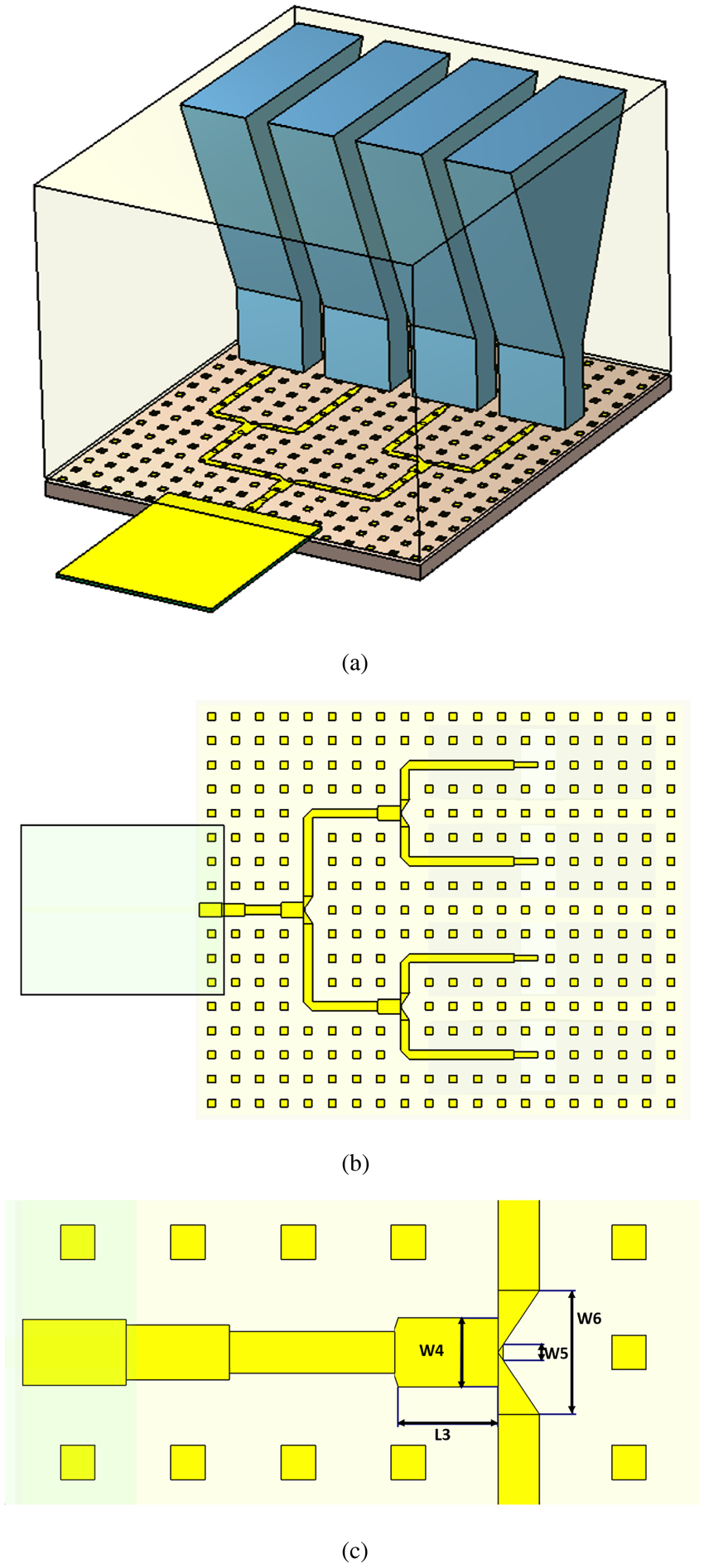
Fig. 9. E-sectoral horn array antenna. (a) Whole structure. (b) Top view with hidden antenna and upper ground. (c) Matching section of the power divider.
Results and discussion
Single element E-sectoral horn antenna
The single-element E-sectoral horn antenna is implemented and simulated based on finite difference time domain; CST and finite element method; HFSS in terms of its radiation performance. In addition, the suggested single-element E-sectoral horn antenna is fabricated as shown in Fig. 8(b) using R&S ZVA67 four ports VNA to validate the antenna design in terms of the reflection coefficient. The radiation performance of the proposed antenna with feeding structure (Fig. 8) in terms of reflection coefficient (S 11) and E-plane and H-plane radiation patterns are presented in Figs 10, 11, and 12, respectively. In Fig. 10, the measured reflection coefficient has fair agreement with the simulated one. Nevertheless, the measured result has a little shift with the simulated result and this occurs due to the fabrication tolerance and soldering process. It is clear that impedance bandwidth of 20% is covering band from 45.7 to 55.4 GHz. A noticeable dip at frequency of 54.5 GHz is occurred near the cut-off band due to the presence of some higher order modes which cause changes in the equivalent current affecting the matching mechanism. For radiation pattern, a fan beam with a wide beam pattern at H-plane and a narrow beam at E-plane is demonstrated. Moreover, a realized gain of an average value of 12.7 dBi is recognized along the operating band as shown in Fig. 13. Also, average radiation efficiency of 90% is achieved, as elaborated in Fig. 14. For radiation pattern performance, the measured and simulated results exhibit good agreement. It is important to point out that the reduction of the radiation efficiency is due to the ohmic loss conducted from both the copper and non-perfect dielectric substrate of the feeding structure (Fig. 7). Moreover, one can notice the fair agreement between both simulated results obtained from the two microwave tools (CST and HFSS).

Fig. 10. Simulated and measured reflection coefficient (S 11) of the proposed RGW E-plane horn antenna shown in Fig. 8(a).
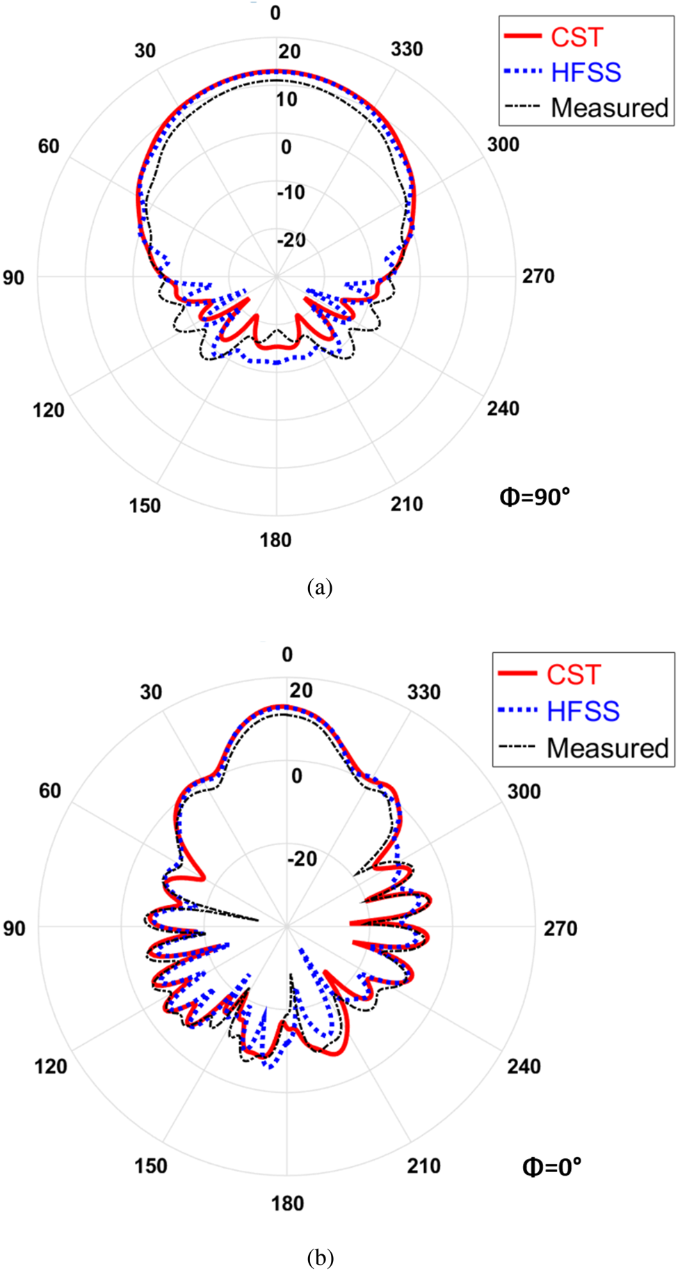
Fig. 11. Simulated radiation patterns of the proposed horn antenna shown in Fig. 8(a) at 47 GHz.
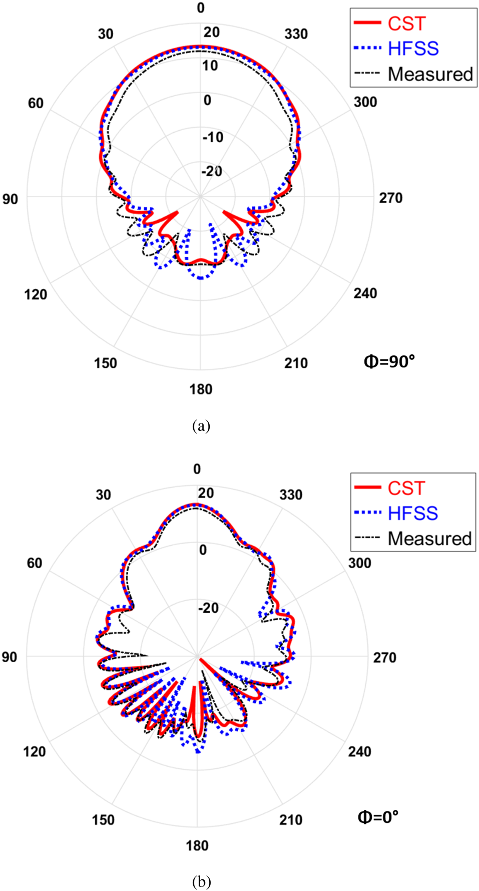
Fig. 12. Simulated radiation patterns of the proposed horn antenna shown in Fig. 8(a) at 50 GHz.

Fig. 13. Realized gain of the proposed RGW E-plane horn antenna over operating bandwidth using CST and HFSS.

Fig. 14. Radiation efficiency of the proposed RGW E-plane horn antenna over operating bandwidth using CST and HFSS.
E-sectoral horn array antenna
For a four-element antenna array, the simulation results including reflection coefficient, E-plane, H-plane radiation patterns, realized gain, and radiation efficiency are realized. In Fig. 15, an impedance bandwidth of fractional bandwidth 20% from 45.7 Hz to 55.4 GHz is achieved. The E-plane and H-plane radiation patterns are elaborated for frequencies 47 and 50 GHz, as presented in Fig. 16 and 17. One can notice that the radiation pattern follows the concept of a wider aperture of the array structure gives a narrow beam width and vice versa. Moreover, an average realized gain of 18.6 dBi and radiation efficiency of 85% are achieved over the entire band, as shown in Figs 18 and 19, respectively. As seen from the previous comparisons, good agreement is noticed between the simulated results obtained from CST and HFSS.

Fig. 15. Reflection coefficient (S 11) of the proposed RGW E-plane horn array antenna shown in Fig. 9(a) using CST and HFSS.
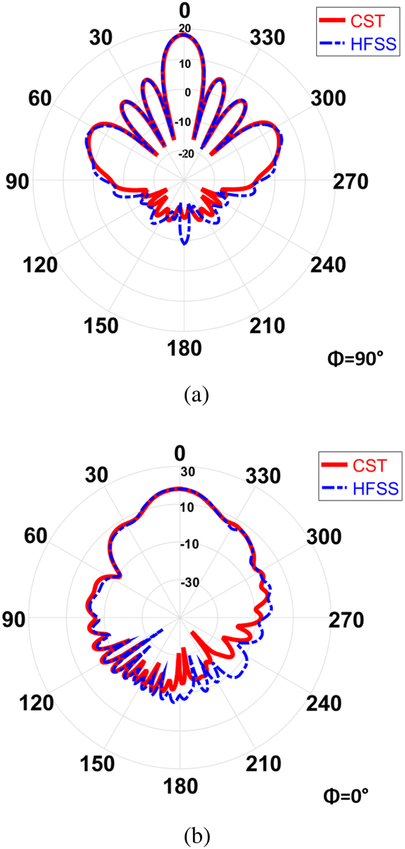
Fig. 16. Simulated radiation patterns of the proposed E-plane horn array antenna shown in Fig. 9(a) at 47 GHz.

Fig. 17. Simulated radiation patterns of the proposed E-plane horn array antenna shown in Fig. 9(a) at 50 GHz.

Fig. 18. Realized gain of the proposed RGW E-plane horn array antenna over operating bandwidth using CST and HFSS.
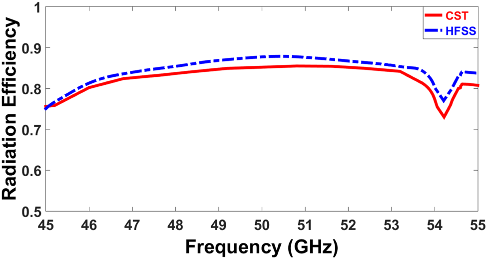
Fig. 19. Radiation efficiency of the proposed RGW E-plane horn array antenna over operating bandwidth using CST and HFSS.
In Table 3, some important radiation pattern features of the proposed work are compared with those of the related H-plane horn antenna using GW and E-plane horn antenna using SIW technology. In this table, the terms “FTBR” and “SLL” refer to “Front to Back Ratio” and “Side Lobe Level”, respectively. Compared with the recently related literature, the proposed single horn antenna structure is wideband and has high radiation efficiency and gain with low SLL and backward radiation. Compared with the horn array antenna proposed in [Reference Ashraf, Sebak and Kishk24], the proposed array design has higher radiation efficiency and gain with lower SLL and backward radiation. That is due to the larger effective area of horn adopted in this work, which is about seven times the horn depicted in [Reference Ashraf, Sebak and Kishk24]. Also, the larger effective array area in the proposed horn array compared with the array in [Reference Gu, Wu and Zhang26] leads to higher gain. The structure may seem to be a bit bulky, but this is in favor of high gain and wide band design.
Table 3. Comparison between the proposed work and the previous literature in terms of some important radiation properties of the horn antenna

Conclusion
In this paper, an E-plane sectoral horn antenna fed by PRGW for future 5G applications is proposed. Designs using PRGW technology have the advantages of low dispersion and low insertion loss. Thus, this design can be considered as a promising candidate for fan beam millimeter applications. A systematic E-plane horn antenna design is realized. The transition from microstrip to PRGW is designed based on quarter wavelength transformer. Moreover, an E-plane horn array is presented to increase the realized gain of the antenna. In this design, the power divider is designed to feed the four-element array antenna. Both antennas are matched to operate in the objective frequency band 45–55 GHz. For the single antenna, an average realized gain of 12.7 dBi is achieved with an average radiation efficiency of 90% over the entire band. Using a four-element array causes an increase of 6 dBi is realized in the average gain with an average radiation efficiency of 85% over the required frequency band.The proposed design is verified by fabricating single-element horn antenna. In addition, the radiation characteristics of both proposed antennas are investigated using two simulation tools (CST and HFSS) to verify the proposed work. Simulated results obtained show fair agreement with measured ones, which makes the proposed designs an attractive candidate for 5G applications. For better pattern radiation and efficiency, different array configurations and different technologies can be used.
Conflict of interest
None.
 M. S. H. Salah El-din was born in Egypt. He received the M.Sc. degree from the Arab Academy for Science and Technology (AASTMT), in 2016, and the Ph.D. candidate in electrical engineering at Ain Shams University, Egypt. His research interests include antenna design and MW technology.
 Shoukry I. Shams (Member, IEEE) received the B.Sc. and M.Sc. degrees in electronics and communications engineering from Cairo University, Egypt, in 2004 and 2009, respectively, and the Ph.D. degree in electrical and computer engineering from Concordia University, Montréal, QC, Canada, in 2016. His research interests include microwave reciprocal/nonreciprocal design and analysis, high power microwave subsystems, antenna design, and material measurement. He received the Faculty Certificate of Honor, in 1999, the Distinction with Honor from Cairo University, in 2004, the Concordia University Recruitment Award.
 A. M. M. A. Allam was born in Cairo, Egypt in 1955. He received the B.S. and M.S. degrees in electrical engineering from MTC and Cairo University in 1978 and 1985, respectively. He received the Ph.D. degree in electrical engineering from Kent University, UK, in 1988. He granted Associate Professorship and Professorship in 1995 and 2000 respectively. He was a Dean and deputy commandant of the MTC, Cairo, Egypt. He was also a dean and vice dean of the Faculty of Information Engineering & Technology in the German University in Cairo. Now he is a head of communication department, German University in Cairo, Egypt. His research interests lie in RF and microwave technology, antenna design, smart antennas for vehicles and radar sensors, satellite communication and diagnoses of censer based on the electromagnetic properties of human organisms. He did a lot of applied research in RADAR absorbing materials. He published hundreds of conference and Journal papers.
 Abdelhamid Gaafar received the B.Sc. and M.S. degrees in electrical engineering from Military Technical College, Cairo and Al-Azhar University Cairo in 1977 and 1983, respectively. He received the Ph.D. degree in electrical engineering & Applied Science from George Washington University, Washington DC in 1989. From 1980 to 1986, he was Instructor at the EE Department, the Military Technical College. From 1995 to 1998, he was the Head of Electrical Engineering Department, the Military Technical College. From 2002 to 2005, he was the Chief Assistance of the Technical Research Center, Egyptian Armed Forces. From 2005 to 2006, he was the Chief Assistance & Head of Research & Development Department Armament Authority Egyptian Armed Forces. From 2006 till now, he is Prof. of Electrical engineering at Electronic and Communication Dept. Arab Academy for Science and Technology and Maritime Transport, Cairo Branch.
 Hadia M. Elhennawy received the B.Sc. and M.Sc. degrees from Ain Shams University, Cairo, Egypt, in 1972 and 1976, respectively, and the Doctorate of Engineering (Dr.-Ing.) degree from the Technische Universitat Braunschweig, Braunschweig, Germany, in 1982. Since 1992, she has been a Professor of communication engineering with the Electronics and Communications Engineering Department, Ain Shams University. In 2004, she became a Vice-Dean for graduate study and research. In 2005, she became the Dean of the Faculty of Engineering, Ain Shams University. Her research interests include microwave devices and subsystems, as well as filters and antennas for modern radar and wireless communications applications.
 Mohamed Fathy Abo Sree was born in Egypt. He received the M.Sc. degree from the Arab Academy for Science and Technology (AASTMT), in 2013, and the Ph.D. degree in electrical engineering from Ain Shams University, Egypt, in 2019. His research interests include antenna design and MW technology. He is reviewing in IEEE ACCESS and PIER online Journal.


