


Introduction
In modern communications, small-size smart space research programs demand multiband transmitter and receiver performances. A multiplexing module is beneficial for these applications which allows the same antenna to be used as a transmitter and receiver at both satellite transponder and earth station telemetry systems [Reference Yuen1]. An efficient and well-organized transmit/receive module needs a multiplexing circuitry to serve two basic functionalities [Reference Yuen1]. First, to isolate the receiver module from high transmitter power as the high power needed for transmission could damage the receiver circuitry [Reference Rammos and Roederer2]. Second, to match the transmitting module to the antenna system such that no power is lost into the receiver system. Thus, the transmitting efficiency is also maintained. To serve these purposes, it is required multiplexing circuits, separate filters, and integration with the other circuitry in the satellite. This makes the overall module complex and large in the size. Thus, printed self-multiplexing antennas are attracting researchers' interest as they combat the need for any extra circuitry for external filters [Reference Yetisir and Mahanfar3]. The size compactness and overall weight of these self- multiplexing antennas are much reduced as compared to external multiplexers. These self-multiplexing antennas, however, have a poor overall gain and a front-to-back ratio (FTBR) [Reference Priya, Dwari, Kumar and Mandal4]. The printed form of these antennas has low power handling capabilities as well.
The substrate integrated waveguide (SIW) based antennas have emerged recently to address the shortcomings of the conventional printed self-multiplexing antennas. SIW based cavity-backed antennas provide high gain, high FTBR, high power handling capability [Reference Chaturvedi, Kumar and Raghavan5,Reference Agrawal and Kumar6], and easy circuit integration. Many attempts have been made in recent literature to develop effective self-diplexing and self-triplexing antennas [Reference Mukherjee and Biswas7–Reference Dash, Cheng, Barik, Pradhan and Subramanian10]. Since self-quadruplexing antennas have four ports for each frequency band, achieving minimum isolation of 20 dB across all four ports is always a challenge [Reference Kumar, Priya, Dwari and Mandal11]. A range of self-quadruplexing antennas based on the SIW technology has been reported by researchers. The SIW cavity loaded with U shape with V Shape slots for multiple resonances is presented for C-band and X-band frequencies respectively [Reference Kumar, Priya, Dwari and Mandal11,Reference Boukarkar and Lin12]. The quad-band operation for C-band application also has been achieved by using the patch loaded in the slot of the SIW cavity [Reference Dash, Cheng and Barik13], however, the cross-polarization level is high, and a poor FTBR occurs by using this technique. Four different quarter mode SIW cavities are placed together for the four resonant frequencies [Reference Kumar14], however, the coupling between the cavities results in a poor FTBR and reduced gain.
In this paper, a self-quadruplexing antenna is proposed by using the TE220 mode of the square SIW cavity for space research applications in Ku-band. Four triangular cavities are formed by placing the array of vias at the position of zero electric walls. Further, four rectangular slots are loaded in four dominant modes of triangular cavity (DMTC) resonators. These slot-loaded DMTC resonators make the antenna design compact and the radiation pattern unidirectional. Also, they provide minimal isolation among all four ports (greater than 28 dB). The proposed design of a self-quadruplexing antenna offers several advantages: extra metallic vias enhance the isolation, enhanced gain, and high front to back ratio achieved in overall antenna performance. The size compactness is also retained and the simple microstrip-feeding reduces the fabrication complexities. The polarization flexibility is also presented in the other variants of the antenna. The equivalent circuit model is developed and the detailed design guidelines are discussed. Further, the easy geometrical design of the proposed antenna provides versatility in tuning the operating frequency of the antenna as per the requirement.
Antenna configuration
The design of the proposed antenna with optimal dimensions for Ku band applications is depicted in Fig. 1. The proposed structure comprises four rectangular-shaped radiating slots loaded in four triangular-shaped SIW cavities. These SIW cavities are excited individually by four microstrip lines of characteristics impedance 50 Ω. A low loss dielectric substrate material RT/Duroid 5870 (ɛ r = 2.33 and loss tangent = 0.0012) with a thickness of 1.57 mm is used for the fabrication of the antenna prototype. Computer Simulation Technology (CST) software is used for the design and simulation of the proposed antenna. In this structure, the SIW cavity dimensions are chosen according to the frequency band of the deep space research applications.
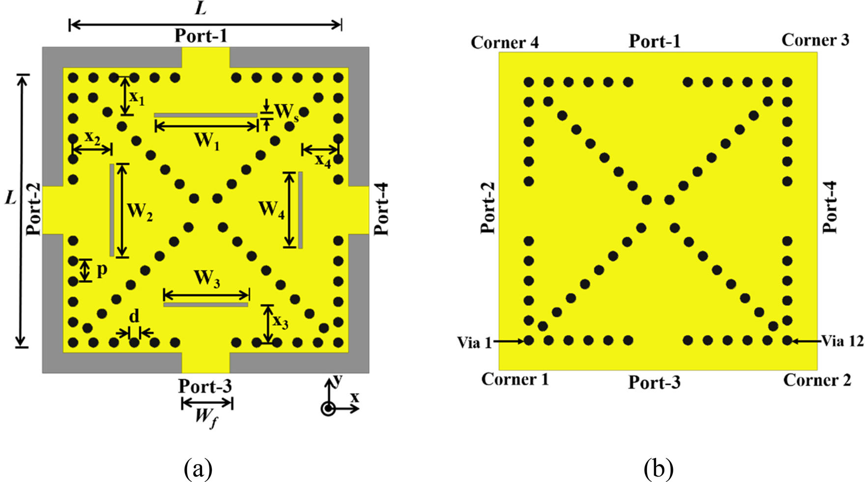
Fig. 1. The layout of Self quadruplexing SIW based antenna (a) Top view (b) Bottom view. [L = 26 mm, X 1,2,3,4 = 3.5 mm, p = 2 mm, d = 1 mm, Ws = 0.5 mm, W 1 = 10.09 mm, W 2 = 9.08 mm, W 3 = 8.25 mm, W 4 = 7.56 mm, W f = 4.7 mm].
A complete understanding of the operating principle of the antenna is achieved by analyzing the modes inside the SIW cavity. In this structure, the SIW cavity dimensions are chosen according to the frequency band of the deep space research applications.
A complete understanding of the operating principle of the antenna is achieved by analyzing the modes inside the SIW cavity. To analyze the quad-resonance modes, the electric field distributions of the SIW cavity are examined using Eigen-mode analysis. The design advancement of the proposed antenna is depicted in Fig. 2. At frequency 12.23 GHz, TE220 mode is observed in the SIW cavity as shown in Fig. 2(a). Four rectangular shape slots are incorporated on the top conducting layer of the substrate at the position of maximum electric field (TE220) inside the SIW cavity (Fig. 2(b)). The length of these slots is kept at approximately half of the guided wavelength (λ g/2) for the broadside radiation. The value of λ g is set 10.09, 9.08, 8.25, 7.56 mm according to the desired resonant frequencies.
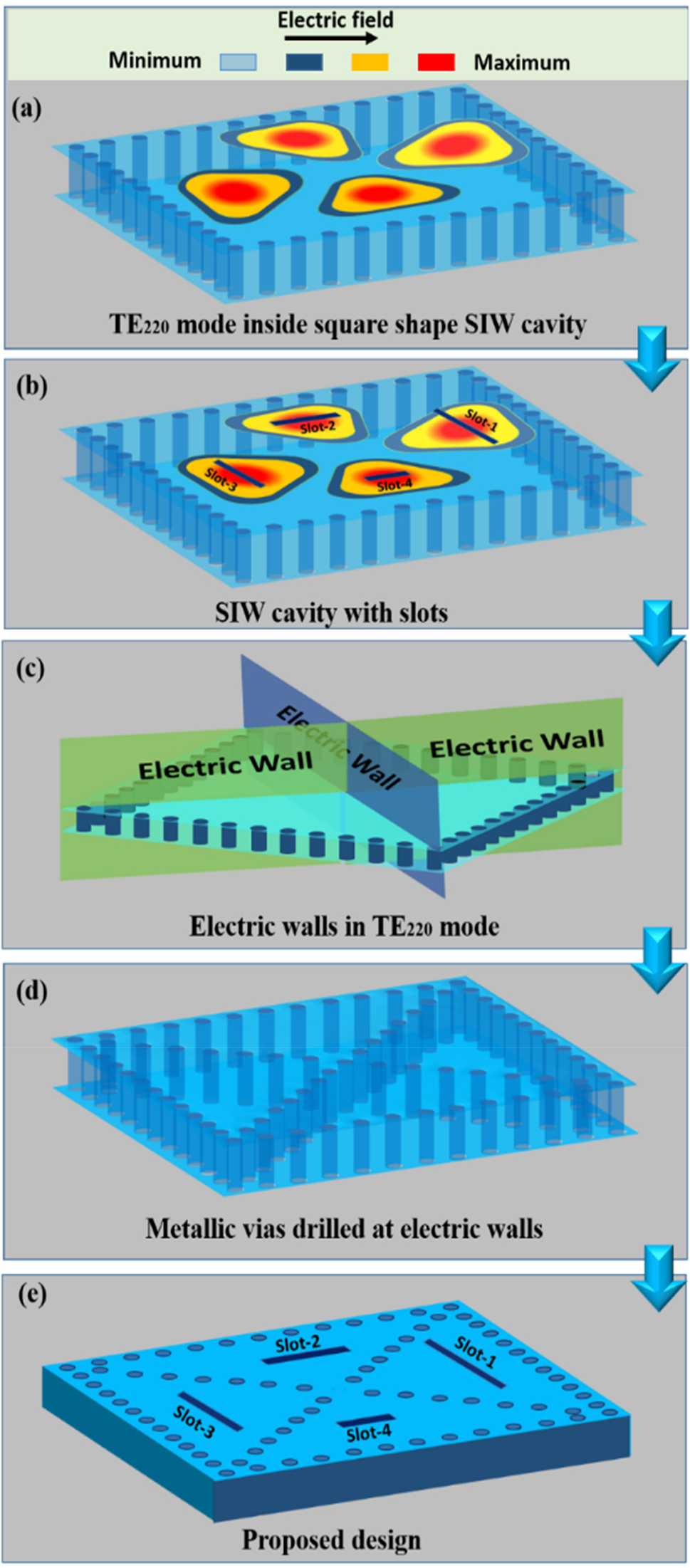
Fig. 2. Design advancement of the proposed self-quadruplexing antenna.
The antenna structure is excited by the four similar edge-fed microstrip lines. It is observed that the resonances occur at 13, 13.5, 14.3 and 15 GHz respectively for each port; however, the port isolations are not found satisfactory. To improve the isolation between all the four ports, the electric walls at the position of the minimum electric field in TE220 mode are analyzed (Fig. 2(c)). The minimal electric field location aids in maintaining the entire mode without compromising any other aspect of the antenna's performance. The metallic perturbation is accomplished by placing an array of diagonal vias at the position of electric walls, enhancing the isolations between the ports without disturbing the four individual resonant frequencies (Fig. 2(d)). Without any other tuning, the final antenna configuration may be viewed as four rectangular slots inside four DMTC (Fig. 2(e)). While incorporating the diagonal via array in square SIW cavity in CST, initially Via “1” was placed at corner-1 (shown in Fig. 1(b)), and the array was extended to corner-3 while keeping the spacing between the vias uniform (center to center 2 mm). In this case, the last via of the array and via of corner 3 will have a distance of 2.77 mm. Similarly, another diagonal via array is incorporated starting from corner-2 to corner-4. Now, these two diagonal arrays will have the via spacing of 2.77 mm at the end of corner-2 and corner-4. Furthermore, as the center most vias of the diagonal arrays were not at all affecting the performance of the antenna, therefore to conserve the mechanical rigidity of the structure the central most via was removed [Reference Deslandes and Wu15].
The S-parameters of the proposed antenna with and without the formation of DMTC are shown in Fig. 3. It can be observed that the incorporation of the metallic vias in the diagonal position enhances the inter-port isolation, bandwidth, and broadside gain without disturbing the resonant frequencies. The proposed antenna can also be made of a set of four separate closely spaced DMTC antennas orthogonal to each other. However, at this instance, the most important aspect of antenna design, namely size compactness, cannot be preserved. Further, the antenna gain and the FTBR will be reduced. The electric field distributions in the SIW cavity structure for each DMTC resonator are shown in Fig. 4.

Fig. 3. Comparison of the S-parameters of self-quadruplexing antenna with and without DMTC (a) Reflection coefficient with gain, (b) Isolation, and (c) Isolation.

Fig. 4. E-field distribution of SIW cavity on exciting (a) Port-1 (b) Port-2 (c) Port-3 (d) Port-4.
Surface-current distribution
The surface current distribution across the four DMTCs is shown in Fig. 5. The rectangular slot length is the key parameter to determine the resonant frequency. The position of the slot is chosen almost in the center of DMTC for the broadside radiation. The surface current is maximum at the extremes of the rectangular slot and tends to degrade along the center of the slot. The current distributions inside all four DMTC are quite comparable, which explains the consistent radiation performance over the full working spectrum. The coupling of the electromagnetic radiation to other radiating slots is minimum when the position of the rectangular slot is kept x 1,2,3,4 = 3.5 mm from via array near the feedline of DMTC. It can be stated that the on excitation of a single port, electromagnetic radiation is exclusively emitted by the respective slot with negligible radiation leaking to neighboring ports. Thus, the proposed structure can be used efficiently as a quadruplexing antenna.

Fig. 5. Surface current distribution of Self quadruplexing SIW based antenna on exciting (a) Port-1 (b) Port-2 (c) Port-3 (d) Port-4.
Equivalent circuit model
For the analysis of the proposed antenna, the equivalent circuit model is developed. As the fundamental design of four DMTC sections corresponding to four ports is identical, therefore the equivalent circuit of a single DMTC section is portrayed in Fig. 6(a). By connecting four such equivalent circuit sections in parallel, the complete equivalent circuit of the self quadruplexing antenna can be achieved. The parallel RLC circuit components (R cn, L cn, C cn (n = 1,2,3,4)) are representing the cavity resonance. The coupling between the input microstrip feed and SIW cavity modes is modeled by the transformer (M 1n (n = 1,2,3,4)). The equivalent of the rectangular slot is presented as the parallel RLC circuit (R sn, L sn, C cn (n = 1,2,3,4)) and is coupled to the SIW cavity using the transformer (M 2n (n = 1,2,3,4)). The loading effect in the DMTC resonator is modeled by introducing a series inductor and capacitor (L nC n) in series with the parallel R cn, L cn, C cn (n = 1,2,3,4) circuit. Initially, the values of the transformer turn ratios, the parallel RLC, and the series LC components are kept constant. Thereafter, to change the reflection coefficient value, the transformer turn ratios and R cn, R sn are varied. The resonant frequency is achieved with the help of the values of L cn, C cn, L sn, C sn, and L nC n. Finally, the values of the components are obtained using Key sight ADS software to get the desired resonances with proper isolation between all four ports. Figures 6(b), 6(c) and 6(d) shows a good agreement between the S-parameters of the proposed antenna simulated through CST software and the equivalent circuit model.

Fig. 6. (a) Equivalent circuit model (ECM) of the proposed antenna, Comparison between the simulated and ECM (b) Reflection coefficient, (c, d) Isolation of the self quadruplexing antenna. Circuit component values: R L = 4.8Ω, M 11 = M 12 = M 13 = M 14 = 1.9, R c1 = 1.4 KΩ, L c1 = 0.44 nH, C c1 = 0.52 pF, R c2 = 1.36 KΩ, L c2 = 0.52 nH, C c2 = 0.52 pF, R c3 = 2 KΩ, L c3 = 0.27 nH, C c3 = 0.77 pF, R c4 = 3 KΩ, L c4 = 0.8 nH, C c4 = 0.21 pF, C 1 = 4.8 pF, C 2 = 2 pF, C 3 = 3 pF, C 4 = 1.8 pF, L 1 = 0.8 nH, L 2 = 0.52 nH, L 3 = 4 nH, L 4 = 1 nH, M 21 = M 22 = M 23 = M 24 = 1.96, R S1 = 11 KΩ, L S1 = 0.673 nH, C S1 = 0.55 pF, R S2 = 0.418 KΩ, L S2 = 0.48 nH, C S2 = 0.47 pF, R S3 = 0.3 KΩ, L S3 = 0.374 nH, C S3 = 0.377 pF, R S4 = 0.28 KΩ, L S4 = 0.3 nH, C S4 = 0.302 pF.
Parametric analysis
Effect of variation of slot length
For the parametric study, the response of one DMTC is taken (in this case for port-3) and a similar parametric response is expected from all other DMTC due to symmetry. Figure 7 shows the variation in S 33 by varying the length of the third radiating slot (W 3). The third resonant frequency shows a forward shift by decreasing the slot length and a backward shift is observed with the increase of slot length. This behavior is also studied in the equivalent circuit model, where the equivalent change in the response is mapped with circuit parameters; it is observed the linear change in the values of resistance R sn and L sn while keeping the C sn fixed. Similarly, the shift in the resonance frequency is can also be observed by fixing the inductor L sn and linearly varying the values of R sn and C sn. Table 1 illustrates the effect of variation in slot length on the component values of R sn, L sn, and C sn.

Fig. 7. Variation of reflection coefficient (S 33) on varying the length of rectangular slot W 3.
Table 1. Effect of variation of slot length

Effect of variation of slot position
The effect of the position of the slot i.e. the distance of the slots from the via holes near the feedlines (x 3) is shown in (Figs 8(a) and 8(b)). By changing the position of the slot in the DMTC, the EM-coupling between the SIW cavity and radiating slot changes. Thus, impedance matching is degraded which results in a change in reflection coefficient and a small impact on isolation levels. In the equivalent circuit model, the change in slot position is controlled by the corresponding slot resistance R sn. Table 2 shows that the value of resistance decreases as the distance x 3 increases. The best isolation level is observed at x 3 = 3.5 mm. More importantly, the change in length and position of the slot in the DMTC is not affecting the resonant frequencies of other ports.

Fig. 8. Variation of (a) Reflection coefficient (S 33) on varying the position of rectangular slot x 3, and (b) isolation on varying the position of rectangular slot x 3.
Table 2. Effect of variation of the slot position

Other polarization variants of the antenna
The antenna proposed in the previous section offers orthogonal polarization between the adjacent ports. However, if the orientation of the rectangular slots is modified without changing the remaining antenna structure. Using this, the choice of polarization can be achieved as per the application. In this proposed antenna variant, the tilted slot at 45° orientation is shown in Fig. 9. If the orientation of all the slots is kept the same (as shown in Fig. 9) then the polarization of the radiation can be achieved in a similar direction (in the direction to the normal to the slot length) for all the ports. The length and width of the rectangular slots are kept the same as that of the original antenna structure.

Fig. 9. Top view of the self-quadruplexing antenna with 45° tilted rectangular slots. [X 1 = 3.5 mm, X 2 = 3.4 mm, X 3 = 3.3 mm, X 4 = 3.26 mm].
Figures 10(a), 10(b) and 10(c) illustrate the S-parameters of the antenna (with 45° tilted slots). It can be observed that almost similar resonances are obtained at 13, 13.5, 14.3 and 15 GHz, however, a small variation in the level of isolation is observed. The radiation pattern of the antenna for all four ports in two orthogonal planes at phi = 45° and 135°, respectively is shown in Fig. 11. A unidirectional radiation pattern with a similar polarization at all four frequencies is observed. The level of cross-polarization is observed less than 20 dB in the broadside direction. The FTBR is calculated as the difference between the peak gain (dB) in the broadside direction and the gain(dB) in the opposite direction. The FTBR at 13, 13.5, 14.3 and 15 GHz is 25.17, 20, 22.2 and 21.87 dB, respectively.

Fig. 10. Simulated s-parameters of self-quadruplexing antenna with 45° tilted rectangular slots (a) Reflection coefficient, and (b, c) Isolation.

Fig. 11. Simulated radiation pattern of the proposed variant of self-quadruplexing antenna at 13, 13.5, 14.3, 15 GHz.
Simulation and measurement results
The prototype of SIW based self-quadruplexing antenna is fabricated on a 1.57 mm thick RT/Duroid 5870 substrate. The photograph of the fabricated prototype is shown in Fig. 12(a). A comparison between the simulated and measured reflection coefficients (Sii [i = 1,2,3,4]) and isolation (Sij [i = 1,2,3,4; j = 1,2,3,4]) is shown in (Figs 12(a), 12(b) and 12(c)). Four resonant frequencies 13, 13.5, 14.3 and 15 GHz exhibit 2.19, 2.3, 2.23 and 2.1% bandwidth with minimum 28 dB isolation. The measured and simulated radiation patterns observed at four ports at 13, 13.5, 14.3, and 15 GHz in both the xz plane and yz plane (referring to coordinates in Fig. 1) are illustrated in Fig. 13. While measuring the radiation pattern the unused ports are terminated using a matched load of 50 Ω. The linearly polarized radiation is observed at all four ports. The measured cross-polarization level at the four frequencies is less than −20 dB. The radiation pattern confirms the stable and uni-directional nature at all four resonances. The FTBR is observed more than 26.8 dB for all operating frequency bands.

Fig. 12. Comparison between the simulated and measured S-parameters of the proposed antenna (a) Reflection coefficient and peak gain, and (b, c) Isolation.

Fig. 13. Comparison between the simulated and measured radiation pattern of the proposed antenna at 13, 13.5, 14.3, 15 GHz.
Figure 12(a) shows a comparison between the measured and simulated gain of the antenna. The maximum peak gain measured is 7.81 dBi at the 15 GHz band. Table 3 summarizes the measured antenna performance for space research applications. A comparison between the proposed work with the similar work available in the literature is depicted in Table 4. It can be observed from the comparison that the proposed low-profile antenna exhibits enhanced gain, isolation, and highest FTBR.
Table 3. Measured performance parameters of the proposed self quadruplexing antenna

Table 4. Comparative performance analysis of proposed antenna with other SIW based self-multiplexing antennas.

N.R., Not Reported.
Conclusion
The SIW based self-quadruplexing antenna is designed fabricated and tested for Ku-band. The splitting of TE220 mode in square shape SIW cavity is achieved by diagonally placing two metalized via arrays. This is making the four highly isolated DMTC resonators which are fed through the microstrip lines. The incorporation of four distinct rectangular slots makes this antenna independently tunable according to the mid-band frequency requirement in Ku-band. The equivalent circuit of the antenna structure is also presented to tune the operating frequencies. The designed antenna resonates at 13, 13.5, 14.3, and 15 GHz with a minimum 28 dB isolation between the ports. In the measurement, the broadside radiation pattern with a high FTBR (>25 dB) and peak gain of 7.8 dBi is observed. There is a good similarity observed between the measured and simulated results. This unidirectional quadruplexing antenna is suited for space research applications and efficient fixed-satellite services.
 Meha Agrawal received B.Tech and M.Tech degrees from U.P.T.U, Lucknow and N.I.T, Kurukshetra, India in 2008 and 2013, respectively. She is presently a research scholar with the Microwave Communication Section, Indian Institute of Information Technology Design and Manufacturing, Jabalpur, India. Her research areas are the design of SIW based antennas.
 Trivesh kumar received his Ph.D. in electrical engineering from the Indian Institute of Technology Kanpur, India. He is presently an assistant professor in the Department of Electronics and Communication Engineering, Indian Institute of Information Technology, Design and Manufacturing, Jabalpur, India. The main areas of his research feature circularly polarized antennas and analysis, microwave measurements, RFID, substrate integrated waveguide structures, and many more.


