


Introduction
New therapies, such as hypoglossal nerve stimulator devices, are emerging for patients with obstructive sleep apnoea (OSA) who are intolerant of continuous positive airway pressure (CPAP). This device works via direct stimulation of the hypoglossal nerve by an implantable device. The electrode is placed medially on the hypoglossal nerve to selectively stimulate the genioglossus, geniohyoid and intrinsic tongue muscles, thereby maintaining airway patency, increasing airflow and reducing collapsibility of the pharynx.Reference Strollo, Soose, Maurer, de Vries, Cornelius and Froymovich1,Reference Eisele, Smith, Alam and Schwartz2 Hypoglossal nerve stimulators improve both subjective and objective measures of OSA, with data supporting long-term effectiveness at five-years post-implantation.Reference Woodson, Strohl, Soose, Gillespie, Maurer and de Vries3 Device complications are rare but may require reoperation or explantation.Reference Bellamkonda, Shiba and Mendelsohn4 As the popularity of these devices continues to grow, it is important that surgeons are prepared to manage complications and device malfunction.
Materials and methods
Exemption from ethical approval was obtained by the Rush University Medical Center institutional review board. Four cases of post-operative device failure were selectively identified over a 2.5-year course (January 2019 to June 2021) at the senior author's (PL) practice in a large, urban, academic referral centre in the Midwestern USA; these cases are detailed below. All patients were implanted with the Inspire® hypoglossal nerve stimulator because it was the only Food and Drug Administration approved device in the USA at the time of this study.5
Results
Case 1
A 51-year-old male with severe OSA who was intolerant of CPAP therapy underwent right-sided implantation with an Inspire II hypoglossal nerve stimulator device (model 3028 implantable pulse generator) via the 3-incision technique.5
At the one-month post-operative visit, the device was activated with no tongue motion despite high voltage settings at various electrode configurations. The patient had no history of trauma or vigorous activity. A computed tomography (CT) scan of the neck demonstrated that the cuff was directed caudally and malpositioned below the digastric muscle (Figure 1). Two additional weeks passed without return of function. At this time, the team proceeded with neck exploration.

Fig. 1. Computed tomography (CT) scans of the neck for case 1. (a) Axial plane CT scan of the neck (arrowhead indicates wire). (b) Axial plane CT scan of the neck (arrow indicates cuff). (c) Coronal plane CT scan of the neck (arrowhead indicates wire). (d) Coronal plane CT scan of the neck (arrow indicates cuff). (e) Sagittal plane CT scan of the neck (arrowhead indicates wire; arrow indicates cuff). (f) Three-dimensional CT scan reconstruction demonstrating the cuff is clearly oriented more inferiorly and directed caudally in comparison to the expected course of the nerve. In comparison to Figure 3, the cuff is positioned more inferiorly and posteriorly, hanging below the anterior belly of the digastric muscle in a more caudal orientation (arrow indicates cuff). The anchor remains attached to the digastric muscle.
In the operating room, the device's stimulator cuff was found to be extruded off the hypoglossal nerve and turned approximately 90 degrees caudally from its normal and expected orientation. The wire of the device was running across the nerve in a perpendicular fashion. Great care was taken to free the device from this location. There was no gross damage to the stimulator cuff, so the same cuff was wrapped around the medial branches of the right hypoglossal nerve under the operating microscope with proper stimulation subsequently.
At the patient's one-week follow-up visit, the device was interrogated with strong tongue motion. The patient is two years post-revision and is tolerating the device with decreased snoring and subjectively improved sleep quality. He is scheduled for repeat polysomnogram.
Case 2
A 62-year-old male was referred to our practice for severe pain in the right-side lateral chest extending into the neck, which had persisted for 9 months after hypoglossal nerve stimulator implantation. The patient was unable to titrate above 0.6 V because of pain and thus unable to use the device. In clinic, the implantable pulse generator functioned appropriately on interrogation. A non-contrast CT scan of the neck and chest was performed. On review, the respiratory sensor lead tunnelled through the pectoralis major muscle and travelled between the pectoralis major and minor muscles rather than taking the typical subcutaneous course above the pectoralis musculature. The stimulator lead also tracked closely along the sternocleidomastoid muscle in a location that corroborated with the patient's neck pain (Figure 2).
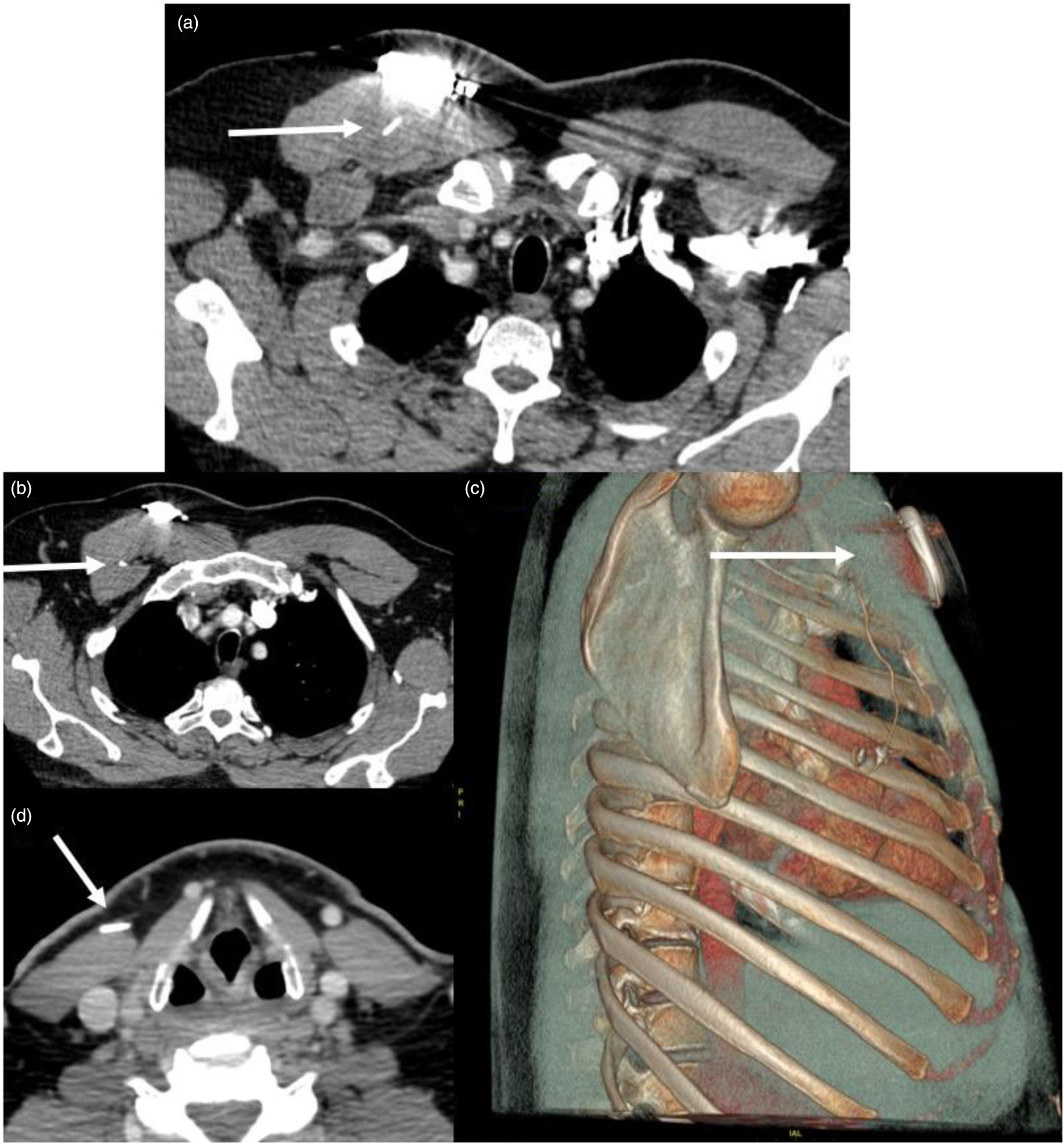
Fig. 2. Neck and chest computed tomography scan for a patient with pain because of lead tethering (case 2). (a) Axial computed tomography scan of the chest demonstrating the sensory lead (arrow) tunnelling through the pectoralis major muscle and coursing between the pectoralis major and minor muscle (b). The three-dimensional reconstruction (c) demonstrates the sensory lead's full (arrow) course through the pectoralis major muscle (hazy grey) to the intercostal space. (d) Axial computed tomography scan of the neck at the level of the thyroid cartilage with the stimulator wire (arrow) tunnelling within the sternocleidomastoid muscle at the site of the patient's pain.
The patient attempted a six-week course of physical therapy without symptom resolution and subsequently proceeded to the operating room for device explantation. Scarring was noted at all three operative sites and was most significant surrounding the hypoglossal nerve. The stimulator cuff was removed via meticulous dissection with the operating microscope, and the intact nerve was subsequently stimulated with strong function.
The patient's pain improved post-operatively but persisted for three months and was not resolved until the nine-month visit.
Case 3
A 69-year-old female underwent right-sided implantation with an Inspire II hypoglossal nerve stimulator device (model 3028 implantable pulse generator) via the 3-incision technique.5
Initial intra-operative interrogation demonstrated that the device was not functioning appropriately. The implantable pulse generator failed to sync properly to the physician programmer, and it was determined that the implantable pulse generator needed replacement. The implantable pulse generator was disconnected and replaced with a new implantable pulse generator, which confirmed an adequate sensory waveform and strong genioglossus activation with stimulation at 0.5 V and 1.0 V.
The patient followed an expected post-operative course and reported daily use and excellent tolerance at two months. The non-functioning implantable pulse generator device was analysed by the Inspire team, confirming that the generator had intermittent stimulation output because of a faulty circuit board connection.
Case 4
A 75-year-old man presented 4 years after right-side hypoglossal nerve stimulator implantation because his device had spontaneously stopped functioning. He had a cardiac history with a left-sided implantable cardiac device. In clinic, the implantable pulse generator was interrogated, and all impedance values were low. Brief, uncoordinated tongue movements were noted, but the device was unable to be activated in a meaningful manner at any voltage. The patient proceeded to the operating room for implantable pulse generator explantation and replacement. A model 3028 implantable pulse generator was replaced and tested in the operating room with simultaneous activation of the implantable cardiac device. The new implantable pulse generator functioned appropriately. The patient was seen two-months post-operatively and was a daily user with return of function of his device.
Discussion
Device characteristics on computed tomography
Very recently, a 5-year (2014–2019) review of the Manufacturer and User Facility Device Experience database was published; it noted 32 hypoglossal nerve stimulator device-related adverse events that resulted in revision surgery and 17 that resulted in device explant.Reference Bellamkonda, Shiba and Mendelsohn4 Device and lead malposition or migration accounted for nearly half (15) of the revision surgery procedures, although the incidence of migration in large, longitudinal studies is less than 1 per cent.Reference Woodson, Strohl, Soose, Gillespie, Maurer and de Vries3,Reference Thaler, Schwab, Maurer, Soose, Larsen and Stevens6 Figure 1 and Figure 3 detail important CT scan imaging findings for the stimulator lead. When positioned properly, the radiopaque, three-pronged stimulation cuff (Inspire II) should be visualised in the inferior sublingual space, oriented anteriorly in the axial plane and mirror the expected course of the nerve (arrow, Figure 3a, d, e). Although the cervical soft tissue relationships may vary between individuals and increasing tissue laxity with age could confound the CT evaluation of device placement, the misaligned stimulation cuff was clear on CT imaging in this case.
• A recent 5-year review characterised 32 hypoglossal nerve stimulator device-related adverse events
• Data from the Stimulation Therapy for Apnea Reduction trial showed 14 cases of mechanical pain but no cases of lead migration or malposition
• In the Acute Decompensated Heart Failure National Registry study with 1017 patients, there were 5 cases of long-term device-related pain and no cases of wire migration
• Imaging studies characterising tongue motion and airway patency with hypoglossal nerve stimulators exist, but none exist for normal or pathological device anatomy
• There are no computed tomography studies of an implanted hypoglossal nerve stimulator
• There are no studies with imaging findings for non-functional devices or lead migration

Fig. 3. Computed tomography (CT) scans of the neck for a properly positioned hypoglossal nerve stimulator. (a) Axial plane CT scan of the neck (arrow indicates cuff). (b) Axial plane CT scan of the neck (arrowhead indicates wire). (c) Coronal plane CT scan of the neck (arrowhead indicates wire). (d) Coronal plane CT scan of the neck (arrow indicates cuff). (e) Sagittal plane CT scan of the neck (arrow indicates cuff; arrowhead indicates wire). (f) Three-dimensional reconstruction demonstrates the course of the lead and proper position of the stimulation cuff in relation to the mandible and hyoid bones. The radiopaque, three-pronged stimulation cuff (Inspire II) should be visualised in the inferior sublingual space, oriented anteriorly in the axial plane and mirror the expected course of the nerve (arrow indicates cuff). The wiring is tunnelled under the anterior belly of the digastric muscle, and the anchor device is secured to the muscle (arrowhead indicates wire).
Although the authors now perform this procedure via a two-incision technique,Reference Kent, Weiner, Chio and Weidenbecher7 it is important to note the proper position of a lateral sensor lead on CT imaging as well. The patient in case 2 was likely experiencing discomfort because of lead-induced scarring and tethering of the pectoralis major and minor muscles. Chest CT imaging allowed the authors to diagnose the misaligned tract (Figure 2). Improper routing causing tethering was reported in only one case in the recent Manufacturer and User Facility Device Experience database review and in no other studies to the authors’ knowledge.Reference Bellamkonda, Shiba and Mendelsohn4
The authors were unable to identify any other studies that presented CT characteristics (expected or pathological) of this device. Thus, the findings in these two cases are extremely valuable examples for surgeons characterising a non-functioning device.
Troubleshooting a non-functioning device
Heiser et al. detailed intra-operative techniques and tips for success, including: adjustments to optimise the position of the respiratory sensor, saline irrigation to dispel air bubbles inside the nerve cuff and implantable pulse generator lead checks to ensure full insertion past the screw block.Reference Heiser, Thaler, Soose, Woodson and Boon8 Also, Soose et al. recently reflected on five years of hypoglossal nerve stimulator implantation experience and detailed an algorithm for post-operative management and troubleshooting to improve patient tolerance and sleep outcomes.Reference Soose, Faber, Greenberg, Boon, Woodson and Strollo9 However, there are few recommendations in the literature for work-up and management of non-functional devices.
Post-operatively, patients should refrain from using the device for the first month to allow for proper healing and encapsulation of the stimulation lead.5,Reference Soose, Faber, Greenberg, Boon, Woodson and Strollo9 However, our practice performs a short test stimulation at one week. Our institution's algorithm for diagnosis and management is presented in Figure 4. Although this is only one example, it provides a framework that may guide clinical decision-making for common causes of device malfunction. If the implantable pulse generator is interrogated and functioning properly but there is no tongue movement, then X-ray and CT imaging should follow as detailed in cases 1 and 2. If the implantable pulse generator is not functioning, then it should be replaced via exploration of the chest incision, and hardware diagnostics should be performed, as in cases 3 and 4. There is no consensus on timing of surgical re-exploration. Based on our experience, performing a short test stimulation at one week does not pose any increased risks to the device, and it can afford the surgeon time to work-up a non-functioning device and allow for exploration of the surgical sites early in the healing process.

Fig. 4. General algorithm for management of device malfunction at the author's institution. The ellipses indicate these are examples of common causes of device malfunction and are not intended to be all-encompassing. IPG = implantable pulse generator; CT = computed tomography; XII = hypoglossal nerve.
Conclusion
Despite the reassuring safety data from large trials,Reference Woodson, Strohl, Soose, Gillespie, Maurer and de Vries3,Reference Thaler, Schwab, Maurer, Soose, Larsen and Stevens6 the hypoglossal nerve stimulator is in the early stages of complication reporting. Device-related complications can be some of the most frustrating to patients and surgeons, and protocols for management will become increasingly important as this treatment modality becomes more widely implemented. In this series, four cases are presented to outline a management algorithm for patients with a non-functional device.
Acknowledgements
The authors acknowledge Christian Provenza and Jaijeet Toor for their contributions to reviewing cases and compiling literature in the early stages of this project.
Competing interests
None declared


