Introduction
Nowadays, more and more people pay much attention to the data transmission rate and operating bandwidth of the communication system with the development of wireless communication technology. In the past decades, microstrip antennas have been extensively used because of their low profile and easy integration. However, traditional microstrip antenna cannot meet the increasing requirement for wideband applications. A number of methods have been proposed to enhance the operating bandwidth, such as loading parasitic patches, using shorting vias, modifying probe, and etching slots on the patch [Reference Lin, Wang, Chen and Yang1–Reference Khan and Chatterjee4].
The characteristic mode analysis (CMA) defines a series of mutually orthogonal characteristic modes for conductors of arbitrary shape, which could represent the solution of electromagnetic problems accurately. It has been widely used to characterize, design, and evaluate the performance of the antenna [Reference Saraswat and Harish5–Reference Lin and Chen7]. In [Reference Saraswat and Harish5], the wideband response and circular polarization operating in different configurations of the antenna could be understood by using CMA. In [Reference Gao and Lin6], the bandwidth of the multilayer metasurface antenna array is improved by loading local capacitive to manipulate the modal intervals of desired modes. In [Reference Lin and Chen7], the antenna operates with both the metasurface mode and aperture mode. Based on CMA, the contribution of the aperture modes could be justified by the modal radiation power of slot-coupled metasurface antenna.
Recently, metasurface has attracted much more attention due to its advantages of flexibly controlling the amplitude, phase, and polarization of electromagnetic wave. By employing the metasurface in antenna design, the antenna performance has been improved significantly [Reference Liu, Chen and Qing8–Reference Zhang, Song, Pei, Huang and Zhou16]. In [Reference Liu, Chen and Qing8], the two resonance modes are excited concurrently by a microstrip line through a coupling slot, which is under the center gap between the mushroom cells. The antenna achieved 25% impedance bandwidth with 9.9 dBi average gain. In [Reference Lin and Chen9], the quasi-TM30 mode of the metasurface and the mode of slot are excited simultaneously to attain a broad bandwidth of 31%. In [Reference Feng, Chen, Xue and Shi10], the modes TM01 and TM02 of a nonuniform tapered metasurface were excited by a circular patch antenna. The antenna obtained a wide impedance bandwidth of 33.1% and an average gain value of 6.34 dBi. In [Reference Chen, Yang, Xue and Che11], a polarization-dependent metasurface was excited by a slot antenna, and wide operating bandwidth of 55% with stable gain was achieved by combining these resonate modes of the metasurface and slot antenna. In [Reference Alharbi, Balanis and Birtcher13], a metasurface composed of rectangular patches was loaded nearby a square ring antenna, and a wide operating bandwidth of 27% was obtained. Meanwhile, the gain of the antenna was also improved. In [Reference Cao, Meng and Shi14], a 2 × 2 metasurface was excited by a triple-slotted substrate integrated cavity, and three different modes of the metasurface were combined to realize a wide bandwidth of 33% with minor gain ripple. In [Reference Zhang, Song, Pei, Huang and Zhou16], a hexagonal loop-shaped metasurface was excited through the coupling aperture on the ground plane. By combing the modes of the metasurface, a wide bandwidth of 56.3% with stable radiation pattern was achieved.
In this paper, a nonuniform metasurface antenna with stable gain is presented. The metasurface composed of square rings and patches is excited by a slot antenna. Two characteristic modes are selected as major operating modes to achieve stable radiation performance in broad frequency band. Compared with the nonuniform metasurface composed of square patches with different sizes of hexagonal slots [Reference Fan, Li, Zheng, Han, Han and Zhang17], the proposed metasurface has wider mainlobe beam and lower sidelobe level in the higher mode. By assembling the resonant modes of the metasurface and slot antenna, a wideband operation is obtained. The measured results show that the impedance bandwidth of the antenna is 64.57% (4.3 to 8.4 GHz), and the 2 dB gain bandwidth is 36.2% (4.3 to 6.2 GHz) .The proposed antenna could operate well in the C-band.
Characteristic mode analysis of metasurface
Figure 1 shows the configuration and equivalent circuit of the metasurface. As shown in Fig. 1(a), the metasurface is composed of 2 × 2 square ring patches with 12 square patches loaded nearby. Figure 1(b) shows the equivalent circuit of the metasurface. Every unit cell of the metasurface could be equivalent to a series–parallel LC circuit. L 1 symbolizes the unit cell of the metasurface, C 1 indicates the coupling between any pair of unit cells, and C 2 represents the gap of the metasurface and the ground plane. The impedance of the metasurface could be calculated as follows [Reference Supreeyatitikul, Lertwiriyaprapa and Phongcharoenpanich18]:
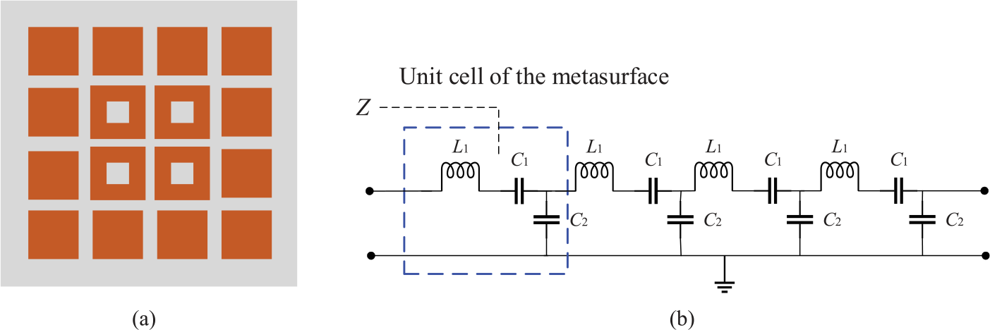
Figure 1. Configuration and equivalent circuit of the metasurface: (a) configuration and (b) equivalent circuit.
The metasurface structure is analyzed using multilayer solver in commercial software Computer Simulation Technology Microwave Studio. Figure 2 shows the CMA of the metasurface. The modal significance of the metasurface is shown in Fig. 2(a). It can be seen that modes J 1/J 2 and J 9/J 10 are two different degenerate modes, and both of them have similar frequency trends. By combing the operating modes J 1 and J 9, a wide operating bandwidth is achieved. The other modes J 3 to J 8 are undesired modes. Figure 2(b) shows the characteristic angle of the metasurface. It is clear that the phase difference of mode J 1/J 2 is almost constant with a value of 180 degrees and that of mode J 9/J 10 is about 165 degrees, which is close to 180 degrees. Figure 2(c) shows the eigenvalue of the metasurface. It is observed that the eigenvalue of mode J 1/J 2 is about zero from 4.0 to 7.0 GHz, and that of mode J 9/J 10 is close to zero from 5.0 to 8.0 GHz.

Figure 2. Characteristic mode analysis of the metasurface: (a) modal significance, (b) characteristic angle, and (c) eigenvalue.
Figure 3 shows the modal currents and radiation patterns of the metasurface. It is obvious that modal currents of modes J 1/J 2 are in the same directions, and a broadside radiation pattern is obtained. Also, some weak opposite currents of modes J 9/J 10 appear on the edge patches, and thus a non-splitting mainlobe with lower sidelobes is obtained.
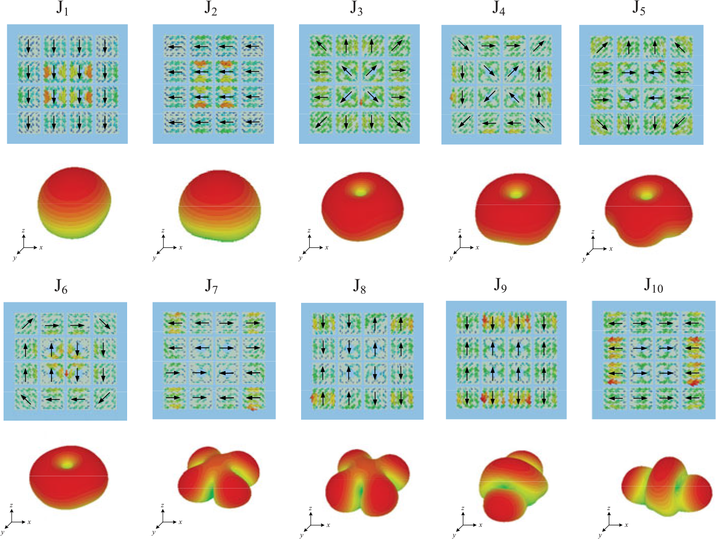
Figure 3. Modal currents and radiation patterns of the metasurface.
Wideband stable gain metasurface antenna
According to the above analysis, a wideband antenna with stable gain based on the aforementioned nonuniform metasurface is presented. The configuration of the proposed antenna is shown in Fig. 4. The metasurface printed on the upper substrate, and the slot antenna is etched on the lower substrate. The slot antenna is composed of a rectangular slot in the ground plane and a microstrip line. A stepped line loaded with a rectangular stub is employed to obtain good impedance matching. The chosen substrates of the nonuniform metasurface and slot antenna are Polytetrafluoroethylene (PTFE) (ε r = 2.2 and tanδ = 0.002). The optimized parameters of the antenna are given in Table 1.
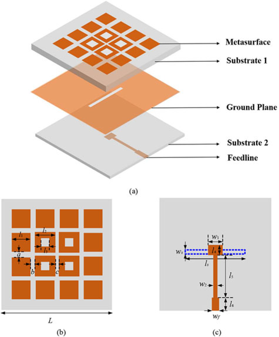
Figure 4. Configuration of antenna: (a) 3D view, (b) top view, and (c) bottom view.
Table 1. Parameters of the proposed metasurface antenna (uUnit: mm)

Figure 5(a) shows the reflection coefficient of the antenna with or without the nonuniform metasurface. It is obvious that the slot antenna before loading the metasurface has a narrower bandwidth from 6.83 to 8.02 GHz. Moreover, the bandwidth of the antenna with the metasurface has been improved significantly, and a −10 dB impedance bandwidth from 4.23 to 7.86 GHz is achieved. Figure 5(b) shows the impedance of the antenna with or without metasurface. It can be seen that, after loading the metasurface, the real and the imaginary part of the impedance are about 50 and 0 ohms, respectively. Then good impedance matching is achieved in the whole operating band.
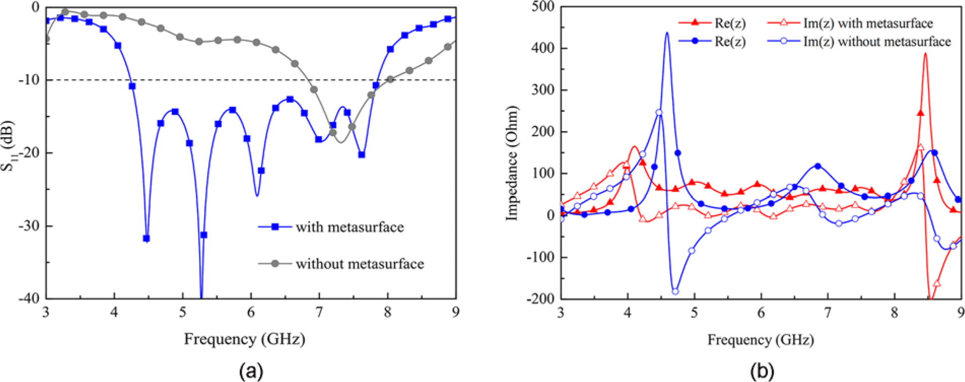
Figure 5. Simulated results of the antenna with or without metasurface: (a) S-parameters and (b) Impedance.
In order to explain the working mechanism of the antenna, the current distributions are further investigated. Figure 6 shows the current distributions of antenna at 5.0, 6.0, and 7.0 GHz. As illustrated in Fig. 6(a) and (b), it can be seen that the currents mainly concentrate at the center area of the metasurface (i.e., square rings). In other words, mode J 1 is well excited at 5.0 and 6.0 GHz. Similarly, mode J 9 is excited at 7.0 GHz because the currents primarily appear in the edge area of the metasurface (i.e. square patches). That is to say, it is consistent with the CMA of the nonuniform metasurface.
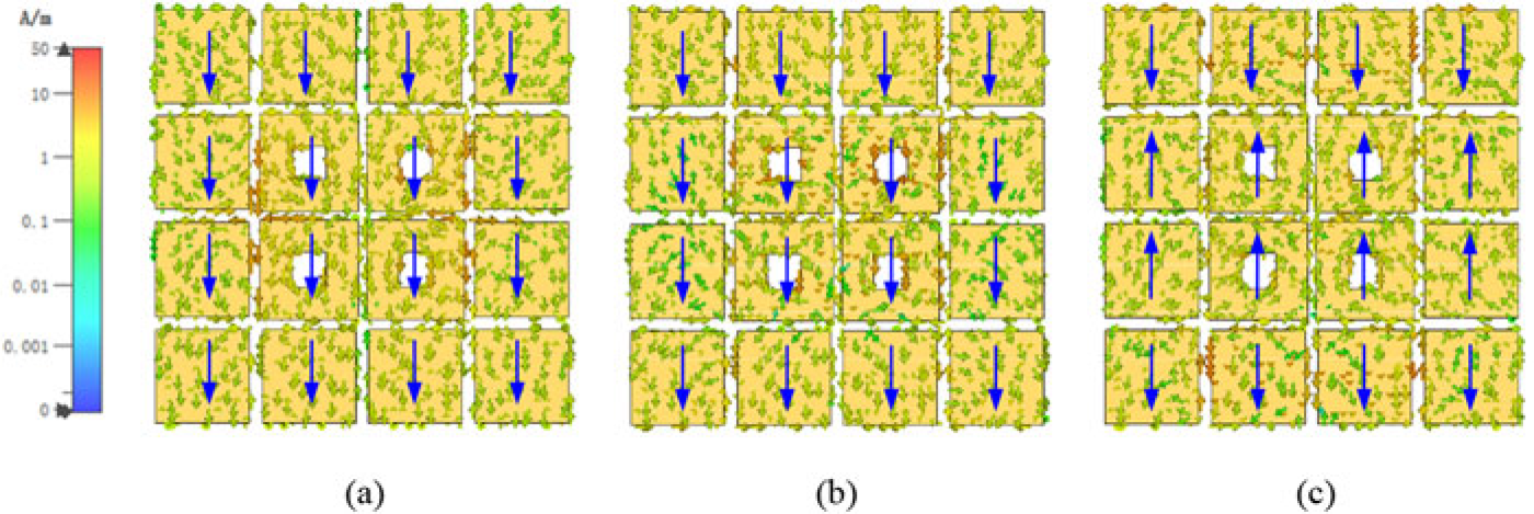
Figure 6. Current distributions of antenna: (a) at 5.0 GHz, (b) at 6.0 GHz, and (c) at 7.0 GHz.
The effect of the structural parameters on the antenna performance is also conducted. It is found that the dimension of square ring patch (l 2), the size of the slot on the ground (length l s and width w s), and the length of the rectangular stub (w 1) play a significant role. The reflection coefficient for different l 2 is plotted in Fig. 7. It is seen that the impedance bandwidth decreases with the increase in l 2. Figure 8 shows the reflection coefficient for different l s. It is seen that when l s increases, the −10 dB impedance bandwidth decreases. Figure 9 plots the reflection coefficient for different w s. With the increase in w s, the impedance bandwidth increases significantly. The reflection coefficient for different w 1 is plotted in Fig. 10. It can be seen that the impedance matching around 5.5 GHz is bad when w 1 = 1.5 mm. Also, the matching becomes worse in the upper band when w 1 increases to 6.3 mm. Considering the trade-off between the operating bands and the impedance matching of the antenna, l 2 = 11.6 mm, l s = 26.6 mm, w s = 2 mm, and w 1 = 3.9 mm are chosen in this paper.
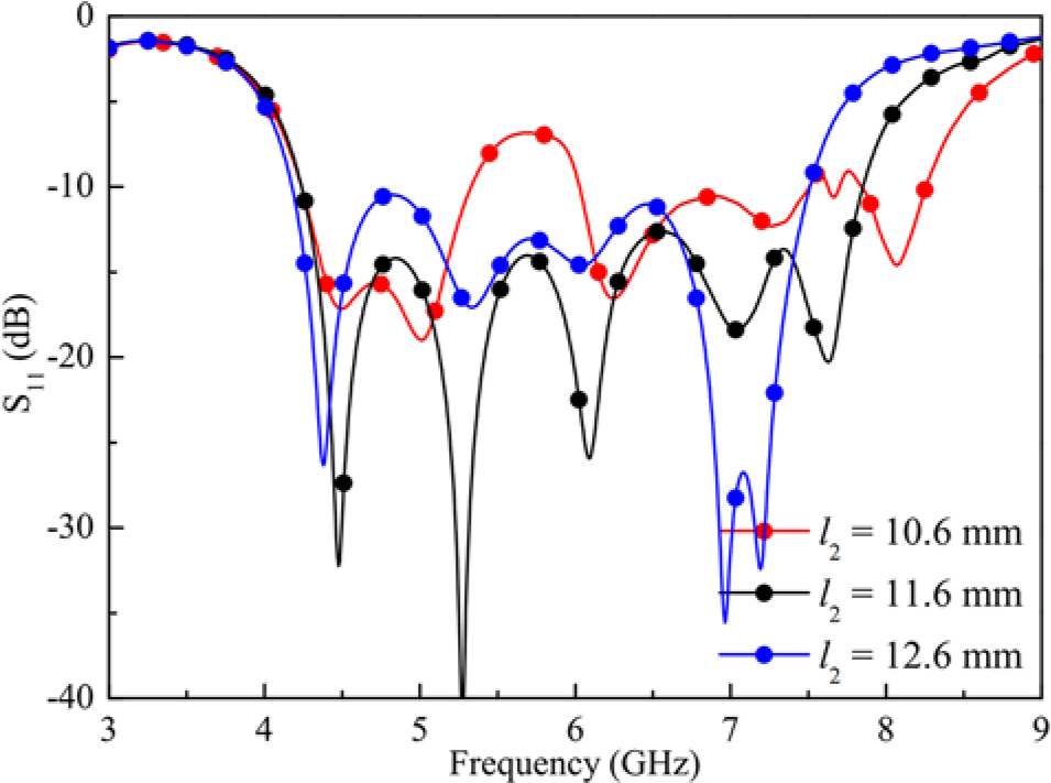
Figure 7. Effect of l 2 on S11.
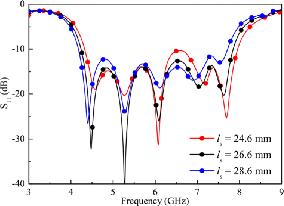
Figure 8. Effect of l s on S11.
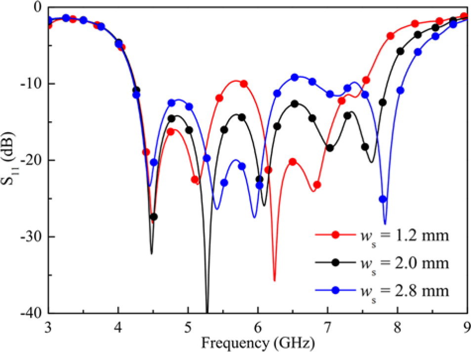
Figure 9. Effect of w s on S11.
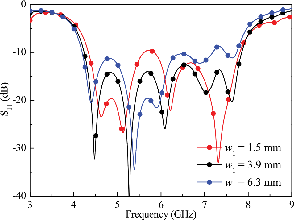
Figure 10. Effect of w 1 on S11.
Measurement results and discussions
A prototype of the proposed wideband metasurface antenna with stable gain is fabricated and measured. Figure 11 shows the photographs of the antenna. The reflection coefficient is measured by an Agilent N5221A vector network analyzer.
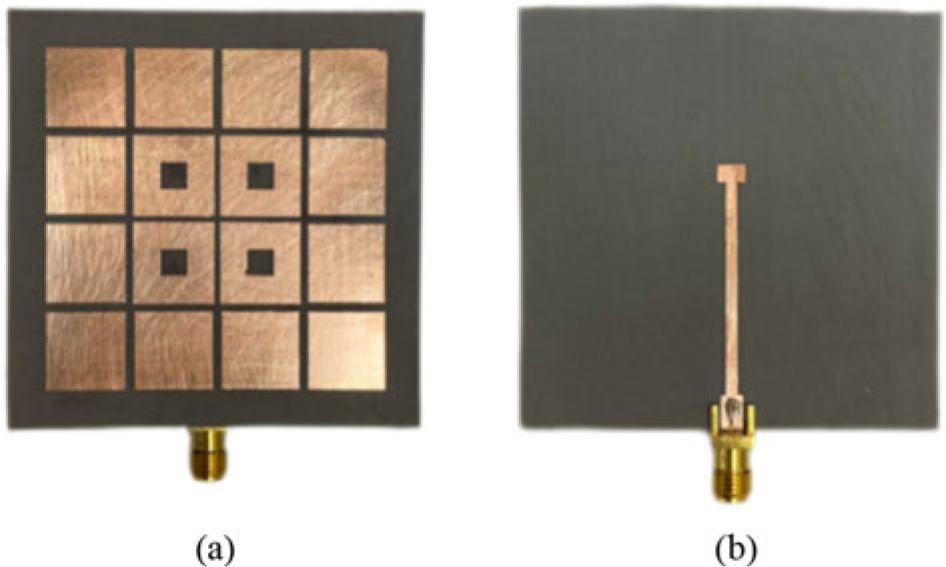
Figure 11. Photograph of fabricated antenna: (a) top view and (b) bottom view.
Figure 12 shows the reflection coefficient of the antenna. It is clear that simulated results between the metasurface antenna and the circuit modeling are basically consistent. It could also be observed that the simulated and measured bandwidth of the metasurface antenna is 60.05% (4.23 to 7.86 GHz) and 64.57% (4.3 to 8.4 GHz), respectively. The difference between the measurement and simulation results is mainly due to the fabrication errors, the effect of the SMA connector, and the deviation of dielectric constant.
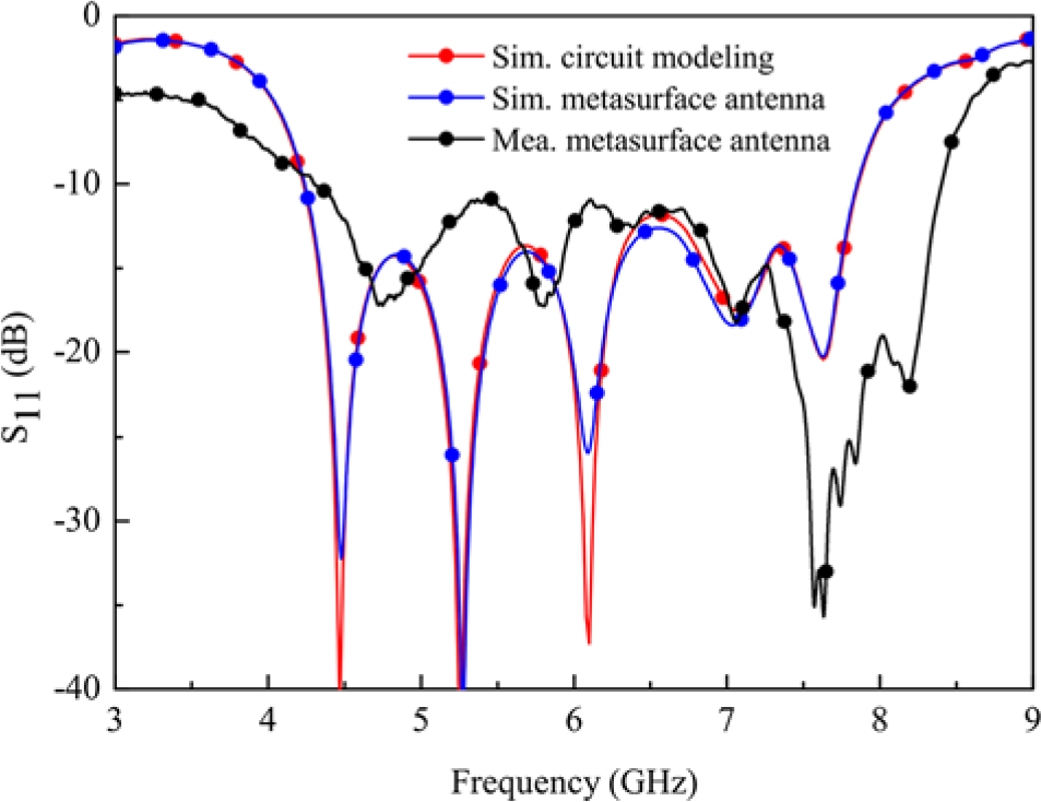
Figure 12. Reflection coefficient of the antenna.
The far-field radiation performance measurement method is illustrated in Fig. 13. A standard horn antenna, as the transmitting antenna, is placed on the transmitting antenna turntable. The metasurface antenna acting as the receiving antenna is placed on the test turntable. The far-field radiation performance measurements, which contain the radiation pattern, gain, and efficiency, are carried out by fixing a transmitting antenna and measuring the received signals of the receiving antenna with a 360° rotation. The far-field radiation performance is measured by a Lab-Volt 8092 antenna training and measuring system in a microwave anechoic chamber.
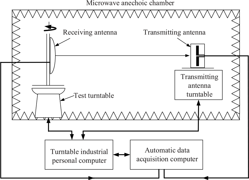
Figure 13. Photographs of the far-field radiation performance measurement method.
Figure 14 plots the normalized radiation patterns at 5.0, 6.0, and 7.0 GHz. It is seen that good agreement between the simulation and measurement results is achieved. Stable broadside radiation patterns and low cross-polarization lower than −19 dB in both E- and H-planes are realized. The simulated cross-polarization level in the E-plane is lower than −60 dB, so the cross-polarization components could not be seen in the normalized radiation patterns. Figure 15 shows the measured and simulated results of the antenna. It can be seen from Fig. 15(a) that the 2 dB gain bandwidth of the measurement is 36.2% (4.3 to 6.2 GHz) with a peak gain value of 9.42 dBi. As shown in Fig. 15(b), the simulated and measured radiation efficiency is about 82% and 80% over the operating band, respectively.
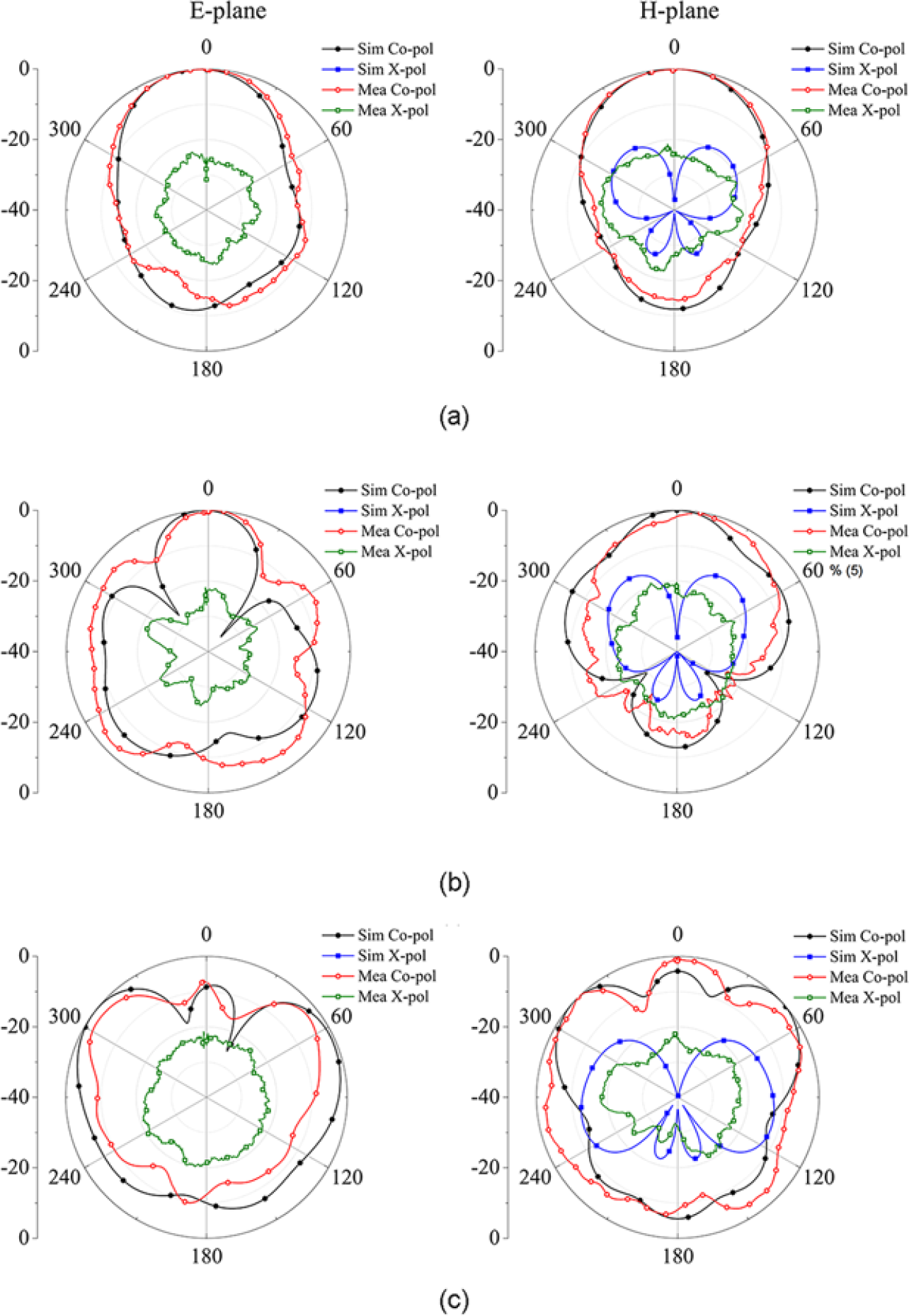
Figure 14. Normalized radiation patterns: (a) at 5.0 GHz, (b) at 6.0 GHz, and (c) at 7.0 GHz.
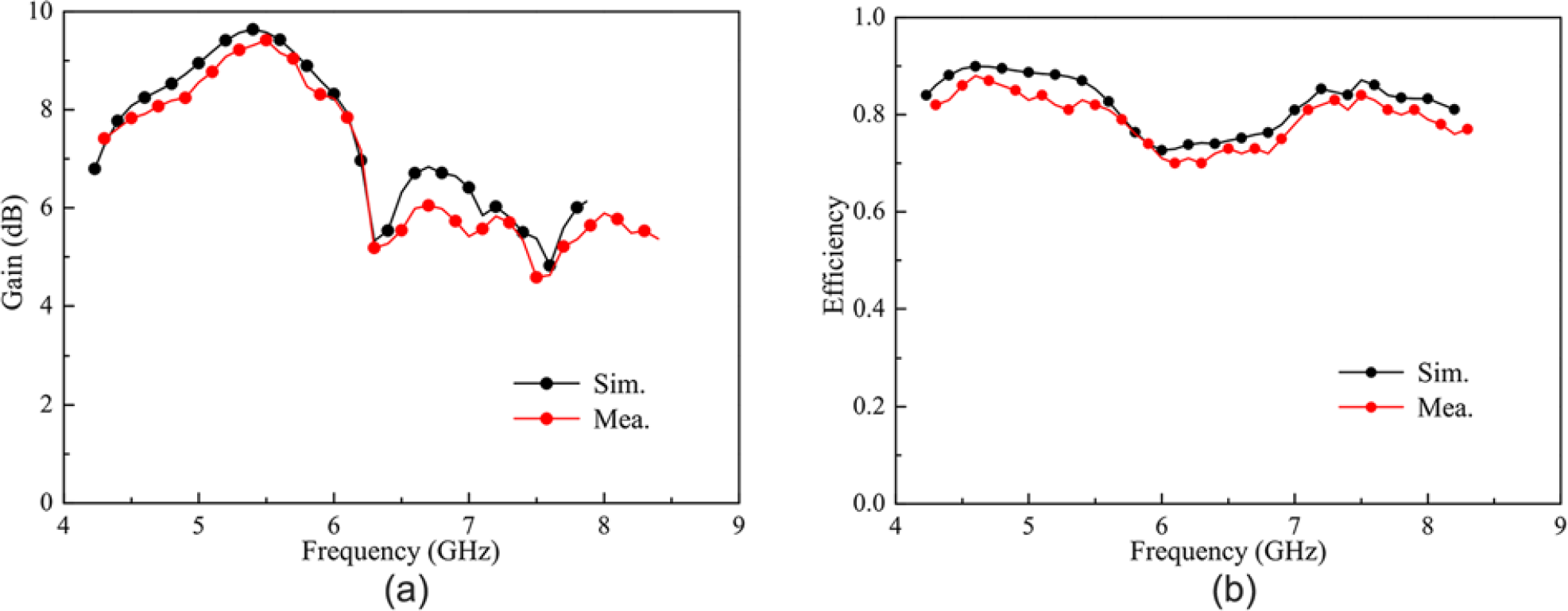
Figure 15. Simulated and measured results of the antenna: (a) gain and (b) efficiency.
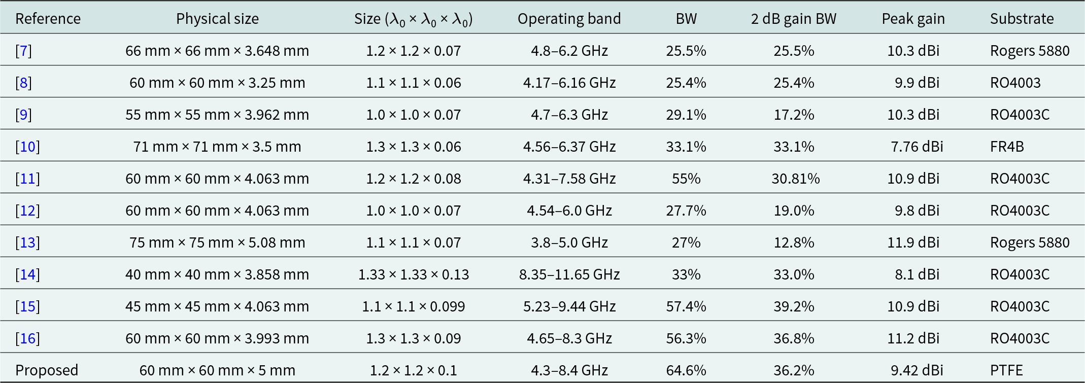
Finally, the comparison of the reported and proposed wideband metamaterial-based antennas is listed Table 2. It is obvious that the proposed antenna has a comparable size, and the largest −10 dB impedance bandwidth with a peak gain value of 9.42 dBi. Moreover, the antenna in this work exhibits a much more stable gain with 2 dB gain bandwidth of 36.2%. Compared to the reported metasurface antennas, which operate in the C-band [Reference Lin and Chen7–Reference Liu, Chen and Qing12], the proposed metasurface antenna has the biggest −10 dB impedance bandwidth and 2 dB gain bandwidth.
Table 2. Performance of wideband metamaterial-based antenna
Conclusion
This paper presents a novel wideband nonuniform metasurface antenna with stable gain. The metasurface is composed of square rings and patches. Two characteristic modes with same current directions are selected as operating modes to achieve stable radiation performance in the wideband frequency. By directly adjusting the size of the central square ring and the edge patch, the bandwidth of the nonuniform hybrid metasurface could be controlled flexibly. The metasurface is excited by a slot antenna. By combining the resonant modes of the metasurface and slot antenna, the wideband stable radiation pattern is achieved. The measured results show that the −10 dB impedance bandwidth of the antenna is 64.57% (4.3 to 8.4 GHz), and the 2 dB gain bandwidth is 36.2% (4.3 to 6.2 GHz) with a peak gain value of 9.42 dBi. The proposed antenna has the potential for C-band applications.
Data availability
Data sharing is not applicable to this article as no new data were created or analyzed in this study.
Acknowledgements
Associate professor Guorui Han is the first author and corresponding author. Zijun Zheng is the second author. Thanks to Jinrong Su, Hao Yuan, and Professor Wenmei Zhang for their suggestions and guidance on this research.
Author contributions
Zijun Zheng performed the simulations, Guorui Han guided the design, Jinrong Su, Hao Yuan, and Wenmei Zhang provided support during the experiment. All authors contributed equally to analyzing data, in reaching conclusions, and in writing the paper.
Funding statement
This work was supported by the National Natural Science Foundation of China (62071282 and 61771295), Natural Science Foundation of Shanxi Province (201901D111027), and Shanxi Scholarship Council of China (2021-006).
Competing interests
The authors report that they have no known conflict of interests or personal relationships that could have appeared to influence the work reported in this paper.

Guorui Han was born in Shanxi Taiyuan, China, in 1977. He received the B.S. and M.S. degrees in Applied Mechanics from Peking University, Beijing, China, in 2000 and 2004, respectively. He received the Ph.D. degree in Radio Physics from Shanxi University, Taiyuan, China, in 2013. Currently, he is working as associate professor in School of Physics and Electronic Engineering, Shanxi University. His research interests include microwave and millimeter-wave antenna and MIMO antenna.

Zijun Zheng was born in Shanxi Taiyuan, China, in 1995. She received the B.S. degree in College of Software Engineering, Taiyuan University of Technology, Taiyuan, China, in 2018. She is currently pursuing the M.S. degree in College of Physics and Electronic Engineering, Shanxi University, Taiyuan, China. Her research is mainly focused on metasurface antenna design.

Jinrong Su was born in 1981. She received the B.S. and M.S. degrees in electronic engineering, in 2004 and 2007, respectively, from Shanxi University, Taiyuan, China, and the Ph.D. degree in radio physics, in 2017. She is working as associate professor in the Department of Electronics and Information Engineering, Shanxi University. Her research interests include TSV modeling and application of TSV in passive devices.

Hao Yuan was born in Shanxi Datong, China, in 1981. He received the B.S. degree in Communication Engineering from China University of Mining and Technology, Jiangsu, China, in 2004. He received the M.S. degree in Computer Aided Process Engineering from Niederrhein University of Applied Sciences, Germany, in 2007. Currently, he is working in School of Physics and Electronic Engineering, Shanxi University.

Wenmei Zhang was born in Shanxi Taigu, China, in 1969. She received the B.S. and M.S. degrees in Electronic Engineering from Nanjing University of Science and Technology, Nanjing, China, in 1992 and 1995, respectively, and the Ph.D. degree in Electronic Engineering from Shanghai Jiao Tong University, Shanghai, China, in 2004. Currently, she is working as professor in School of Physics and Electronic Engineering, Shanxi University, Taiyuan, China. Her research interests include microwave and millimeter-wave integrated circuits, EMC, and microstrip antenna.


